These pages should help
you add that discriminator tap to your scanner. Older scanners (generally)
use DIP ICs for discriminator chips, making it easier to solder one's connections.
Nowadays, manufacturers tend to use SOIC-packaged chips (much smaller!).
So, be careful with that iron. Here's a documentary of my new PRO-2048's
discriminator modification. A note: although this shows the modification
of one particular scanner, many, many other scanners can be modified in
the same fashion. Usually the only problem is finding the discriminator
chip!
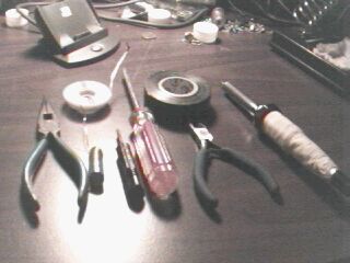
0. Prepatory: Here are the tools that you will need to
open up the radio and do what you need to do.
As you can see, this includes needlenose pliers, wire cutters, assorted philips-head screwdrivers, electrician's tape, solder, desoldering braid, and a soldering iron with a fine tip. Use a low wattage iron to prevent getting the IC too hot.
You will need a few parts also.
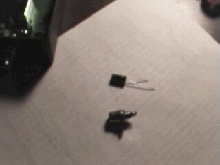
The parts are difficult to see here, but the little blob
on the top is a 10uf electrolytic capacitor (RS part #272-1025). The little
doohickey on the bottom is a panel-mount RCA jack (RS part #274-346, for
a 4-pack). The cost of both of these was around $3.30 or so.
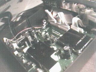
1. The cover is removed, showing the board, speaker, and
other components.
2. In order to get the board out, one needs to first disconnect
all of the molex connectors (the plug-thingies). There are a total of 5,
make sure you get them all! After that's completed, you need to desolder
the connectors for the radio's backlight. Simply hold onto one wire at
a time, with gentle pressure, and apply the iron to the connection on the
board. The wires should pop right off.
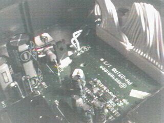
The wires we're talking about are the 2 large, white wires in the upper center of the picture.