Writing an Operating System is easy. Explaining how to write one isn't. Most introductory articles on the same obfuscate the workings of the necessary components of an OS with design paradigms the writers feel best complement the OS. This article, the first in my series on just how a modern OS works, is different—it tries to properly, yet succinctly, explain all the requisite components of an OS—in 512 bytes per article.
The magic begins with the processor starting execution on reset at the linear address
0xFFFFFFF0. This location contains a jump to the Basic Input/Output System
(BIOS) code, which starts with the Power On
Self Test (POST), followed by initialization of all requisite devices. In a
predetermined order, the BIOS then checks for any bootable storage medium in
the system. Except for optical drives, a bootable disk is indicated via
a 16-bit 0xAA55 identifier at the 510-byte mark (end of first 512-byte sector).1
If a bootable medium is found, the first sector is loaded at the linear address
0x7C00 and jumped to. If none is found, the BIOS lovingly displays "Operating
System not found."2
Real Mode
The first ancestor of today's x86 architecture was the 8086, introduced in 1978. The processor featured no memory protection or privilege levels. By 1982, Intel had designed and released the 80286, which featured hardware-level memory protection mechanisms, among other features. However, to maintain backward compatibility, the processor started in a mode compatible with the 8086 and 80186, known as real mode. (Feature wise, the mode lacks realness on all accounts.)
Real mode features a 20-bit address space and limited segmentation. The mode featuring memory protection and a larger address space was called the protected mode.
Note that the 16-bit protected mode introduced with the 80286 was enhanced with the 80386 to form 32-bit protected mode. We will be targeting only the latter.
Segmentation
The 8086 had 16-bit registers, which were used to address memory. However, its address bus was 20-bit. To take advantage of its full width and address the entire 1MiB physical address space, the scheme of 'segmentation' was devised.
In real-mode segmentation, 16-bit segment registers are used to derive the linear address. The registers CS, DS, SS, and ES point to the current code segment, data segment, stack segment respectively, with ES being an 'extra' segment.
The 80386 introduced the FS and GS registers as two more additional segment registers.
The 16-bit segment selector in the segment register yields the 16 significant
bits of the 20-bit linear address. A 16-bit offset is added to this segment
selector to yield the linear address. Thus, an address of the form (Segment):(Offset) can be interpreted as, (Segment<<4) + Offset.
This, however, can yield multiple (Segment):(Offset) pairs for a linear address. This
problem persists during boot time, when the BIOS hands over control to the
linear address 0x7C00, which can be represented as either 0x0000:0x7C00 or
0x07C0:0x0000. (Even the very first address the processor starts
executing at reset is similarly ambiguous. In fact, 8086 and 80286
placed different values into CS and IP at reset, 0xFFFF:0x0000 and 0xF000:0xFFF0 respectively.)
Therefore, our bootloader starts with a far jump to reset CS explicitly, after which
it initializes other segment registers and the stack.
    ; 16-bit, 0x7C00 based code.
    org 0x7C00
    bits 16

    ; Far jump, reset CS to 0x0000.
    ; CS cannot be set via a 'mov', and requires a far jump.
    start:
        jmp 0x0000:seg_setup

    seg_setup:
        xor ax, ax
        mov ds, ax
        mov ss, ax
Stack
The x86 also offers a hardware stack (full-descending). SS:(E)SP points to the top of the stack, and the instructions push/pop directly deal with it.
        ; Start the stack from beneath start (0x7C00).
        mov esp, start
Flags
A direction flag in the (E)FLAGS register controls whether string operations decrement or increment their source/destination registers. We clear this flag explicitly, which implies that all source/destination registers should be incremented after string operations.
        ; Clear direction flag.
        cld
The A20 Line
On the original 8086, the last segment started at 0xFFFF0 (segment selector =
0xFFFF). Thus, with offset greater than 0x000F, one could potentially access
memory beyond the 1MiB mark. However, having only 20 addressing lines, such
addresses wrapped around to the 0MiB mark. An access of 0xFFFF:0x0010 would
yield an access to 0x0000 (wrapped around from 0x10000) on the 8086.
The 80286, however, featured twenty-four address bits. Delighted hackers, on the other hand, had already exploited the wrap-around of addresses on the 80(1)86 to its fullest extent. Intel maintained backwards compatibility by introducing a software programmable gate to enable or disable the twenty-first addressing line (called the A20 line), known as the A20 gate. The A20 gate was disabled on-boot by the BIOS.
        ; Read the 0x92 port.
        in al, 0x92
        ; Enable fast A20.
        or al, 2
        ; Bit 0 is used to specify fast reset, 'and' it out.
        and al, 0xFE
        out 0x92, al
Protected mode—Segmentation Revisited
The introduction of protected mode featured an extension to the segmentation model, to allow rudimentary memory protection. With that extension, each segment register contains an offset into a table, known as the global descriptor table (GDT). The entries in the table describe the segment base, limit, and other attributes—including whether code in the segment can be executed, and what privilege level(s) can access the segment.
At the same time, Intel introduced paging. The latter was much easier to use for fine-grained control and different processes, and quickly superseded segmentation. All major operating systems setup 'linear' segmentation where each segment is a one-on-one mapping of the physical address space, after which they ignore segmentation.
As paging was extended to cover most cases, segmentation was left with only an empty shell of its former glory. However, it inspired OpenWall's non-executable stack patch and PaX's SEGMEXEC—both of which couldn't have been implemented with vanilla x86 paging.
Note that the new segment selectors are only valid for 32-bit protected mode, and we'll reload them after the switch to that mode.
        ; Disable interrupts.
        cli
        ; Load the GDTR - the pointer to the GDT.
        lgdt [gdtr]

    ; The GDT.
    gdt:
        ; The first entry in the GDT is supposed to be a
        ; null entry, but we'll substitute it with the
        ; 'pointer to gdt'.
        gdtr:
            ; Size of GDT - 1.
            ; 3 entries, each 8 bytes.
            dw (0x8 * 3) - 1
            ; Pointer to GDT.
            dd gdt
            ; Make it 8 bytes.
            dw 0x0000

        ; The code entry.
        dw 0xFFFF       ; First 16-bits of limit.
        dw 0x0000       ; First 16-bits of base.
        db 0x00         ; Next 8-bits of base.
        db 0x9A         ; Read/writable, executable, present.
        db 0xCF         ; 0b11001111.
                        ; The least significant four bits are next four bits of
                        ; limit.
                        ; The most significant two bits specify that this is for
                        ; 32-bit protected mode, and that the 20-bit limit is in
                        ; 4KiB blocks. Thus, the 20-bit 0b11111111111111111111
                        ; specifies a limit of 0xFFFFFFFF.
        db 0x00         ; Last 8-bits of base.

        ; The data entry.
        dw 0xFFFF, 0x0000
        db 0x00
        db 0x92         ; Read/writable, present.
        db 0xCF
        db 0x00
No More Real (Mode)
The switch to protected mode is relatively easy, involving merely setting a bit in the CR0 register and then reloading the CS register to specify 32-bit code.
        mov eax, cr0
        or eax, 1       ; Set the protection enable bit.
        mov cr0, eax
        jmp 0x08:protected_mode

    bits 32
    protected_mode:
        ; Selector 0x10 is the data selector offset.
        mov ax, 0x10
        mov ds, ax
        mov es, ax
        mov ss, ax
Paging
Paging is called paging because you need to draw it on pages in your notebook to succeed at it.
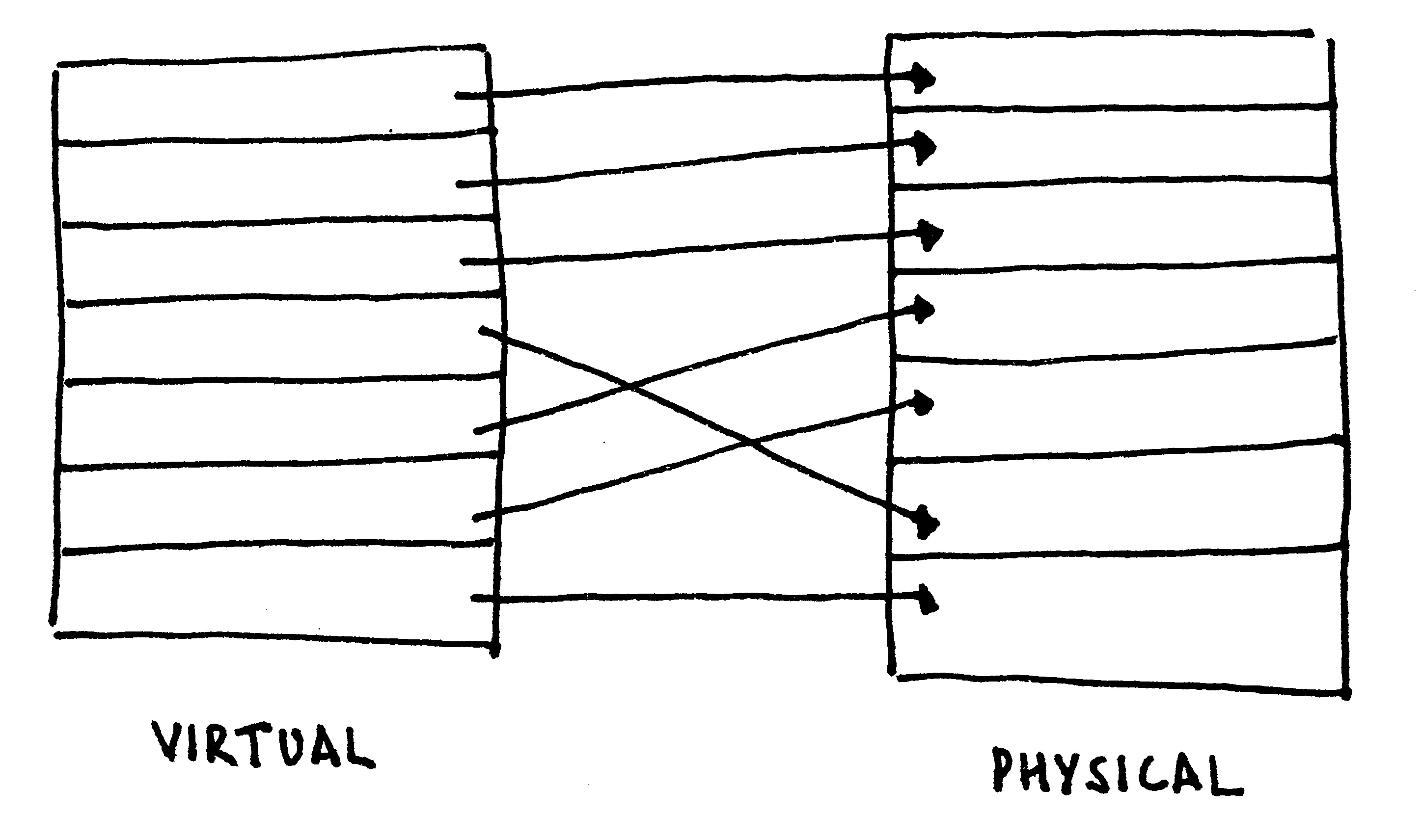
Virtual Memory
The concept of virtual memory is to have per-process virtual address spaces, with particular virtual addresses automatically mapped onto physical addresses for each process. Compared with segmentation, such a technique offers the illusion of contiguous physical memory and fine-grained privilege control.
To brush up the concept of virtual memory, follow along with the hand-drawn illustration in the figure below.
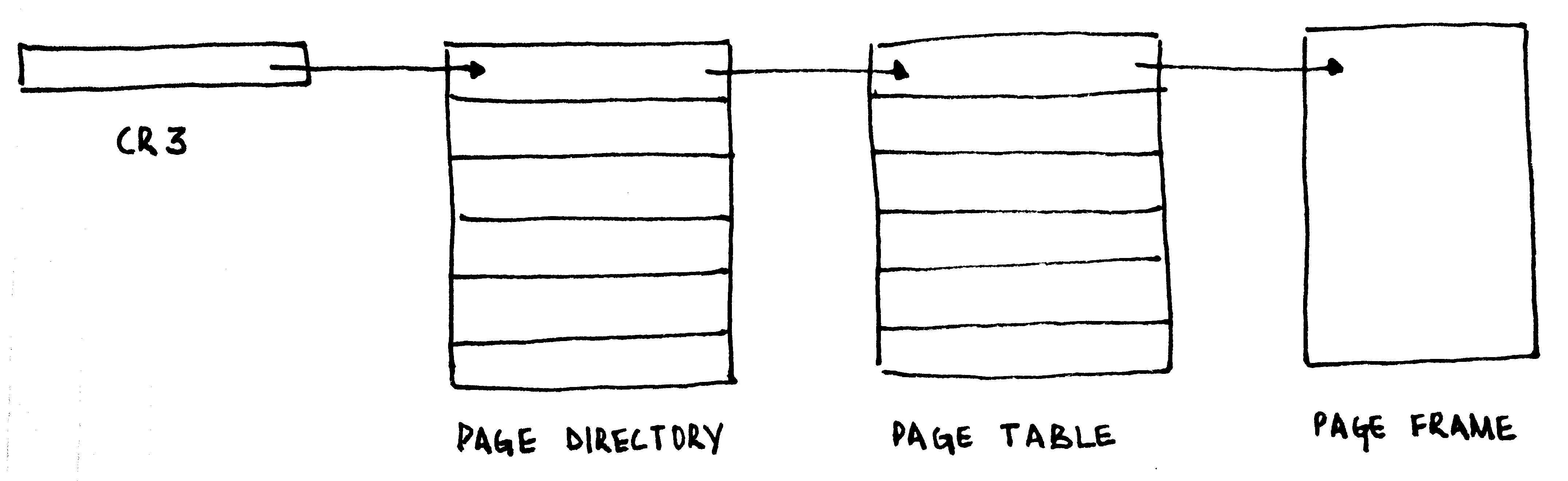
Virtual Memory (x86)
On the x86, the task of mapping virtual addresses to physical addresses is managed via two tables: the page directory and the page table. Each page directory contains 1024 32-bit entries, with each entry pointing to a page table. Each page table contains 1024 32-bit entries, each pointing to a 4KiB physical frame. The page table in entirety addresses 4MiB of physical address space. The page directory, thus, in entirety addresses 4GiB of physical address space, the limit of a 32-bit address space.
The first page table pointed to by the page directory maps the first 4MiB of the virtual address space to physical addresses, the next to the next 4MiB, and so on.
The address of the page directory is loaded into a special register, the CR3.
        ; 0x8000 will be our page directory, 0x9000 will be the
        ; page table.

        ; From 0x8000, clear one 0x1000-long frame.
        mov edi, 0x8000
        mov cr3, edi
        xor eax, eax
        mov ecx, (0x1000/4)

        ; Store EAX - ECX numbers of time.
        rep stosd

        ; The page table address, present, read/write.
        mov dword [edi - 0x1000], 0x9000 | (1 << 0) | (1 << 1)

        ; Map the first 4MiB onto itself.
        ; Each entry is present, read/write.
        or eax, (1 << 0) | (1 << 1)
        .setup_pagetable:
            stosd
            add eax, 0x1000         ; Go to next physical address.
            cmp edi, 0xA000
            jb .setup_pagetable

        ; Enable paging.
        mov eax, cr0
        or eax, 0x80000000
        mov cr0, eax
Extensions to the paging logic allowed 32-bit processors to access physical addresses larger than 4GiB, in the form of Physical Address Extension (PAE). The same also added a NX bit to mark pages as non-executable (and trap on instruction fetches from them).
Recursive Map
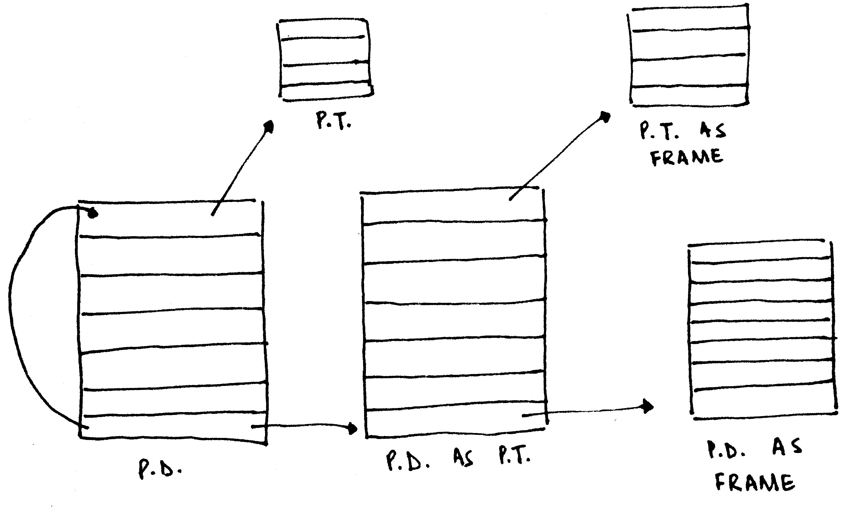
In our simplistic case, the entire first 4 megabytes were mapped onto themselves, to so-called identity map. In the Real World™, however, it is often the case that the physical memory containing the page directory/tables is not mapped into the virtual address space. Instead of creating a different page table to point to the existing paging structures, a neat trick is deployed.
Before explaining the trick, note how the page directory and the page table has the exact same structure, including the attributes. What happens, then, if an entry in the page directory were to point to itself? The page directory will be interpreted as a page table. This 'page table' will have entries to actual page tables. However, the CPU will interpret them as entries corresponding to page frames, allowing you to access them via the virtual address the page directory was self-mapped to. If that makes your head hurt, the illustration above might help.
Translation Lookaside Buffer (TLB)
When a virtual memory address is accessed, the CPU is required to walk through the page tables to determine the page table entry for the specified virtual address. However, walking through the page tables is slow. In the worst case, a walkthrough requires the processor to do a lookup from RAM for the page directory, followed by a lookup from RAM for the page table, where a RAM lookup latency is in the order of 100 times that of a cache lookup latency. Instead, the CPU maintains a cache of the virtual address to physical address translation, known as the Translation Lookaside Buffer (TLB).
When a virtual address is accessed, the CPU first determines if a mapping is present in the TLB. Only if the CPU fails to find one there, it walks through the actual page tables and then populates the TLB with the translation.
A problem with the TLB is that changes across the page table don't get reflected in it automatically.3 On the x86, there exist two mechanisms to flush particular entries in the TLB:
- The instruction
invlpg addressinvalidates the TLB entry for the page that containsaddress. - Reloading CR3 with the address of a page directory flushes all the entries in the TLB.4 5
Till Next Time
The article got us through the backward-compatibility mess that defines the x86 boot process, into protected mode with paging enabled. In the next issue, we'll look at x86 interrupt handling, the programmable interrupt timer, multiprocessor initialization, and then the local APIC timer. We'll also answer some unanswered questions (like what happens if a page table entry doesn't exist) and conclude with a (hopefully) nifty proof-of-code.
Till then,
    hlt:
        hlt
        jmp hlt
-
0xAA55is representable as0b1010101001010101. The alternating bit pattern, with0x55being an inversion of0xAA, was taken as an insurance against even extreme controller failure. The same identifier is also used in other parts of the BIOS interface. ↩ -
There is no deep reason behind
0x7C00being the load address. This is how programming usually works (and standards proliferate). ↩ -
This is how PaX's PAGEEXEC emulates the NX bit by memory trapping with very little performance overhead: it sets the page table entries for the "data" pages to always trap, but allows a data access (i.e., EIP not in the accessed page) to go through. After this, it immediately resets the page table entry, but relies on the TLB for repeated page accesses to not trap. Truly, it is a work of art! --PML ↩
-
CR3 is usually reloaded to change the process context (will be covered across future articles). However, a change of process does not require that the entries for the kernel pages in the TLB get flushed. To avoid so, the global bit in the page table entry can be set, and global pages can be enabled in CR4. Doing so ensures that the entry for the specific page in the TLB can only be invalidated via a
invlpg. ↩ -
The x86-64 architecture saw the introduction of tags as a part of the TLB entry, in 2008. Thus, each TLB entry is associated with a particular tag, and context switches can only involve changing of the current tag. ↩