Beige Box Construction
by The Phoenix
Many tasks involving phone line work (such as installing a new extension, etc.) are much easier when you have a lineman's handset. Since a typical tone/pulse switchable model sells for about $300 many people opt to build their own. Such an improvised handset is called a Beige Box. I will begin this article by repeating the instructions for making one. Next I will mention what the lineman's handset has that the generic box lacks and explain how to add these features.
To construct a basic Beige Box you need a one piece phone, preferably pulse/tone switchable, a pair of alligator clips (one RED and one BLACK for the traditional look), and some tools (wire cutters, wire strippers, long nose pliers, PVC electrical tape, and a soldering iron). If the phone has no line cord you will need that too. Cut the wire about four fee from the phone. Expose and strip the RED and GREEN wires. Connect the RED alligator clip to the RED wire and the BLACK clip to the GREEN wire. For a good connection these should be soldered. Wrap the connections in electrical tape. It's that simple! In the off-hook state this device will behave just like a lineman's handset in the Talk Mode.
Lineman's handsets have a Talk/Monitor switch instead of a switch hook. In the Monitor Mode it does not merely go on-hook like our Beige Box; it becomes a line tap. You can monitor everything which transpires on the line: an indispensable testing aid! If no phones are off-hook you will hear a background hum. If you pick up an extension you will hear the click and dial tone. It will not interfere with rotary dialing. If an incoming call arrives you hear the ringing signal (a loud purring).
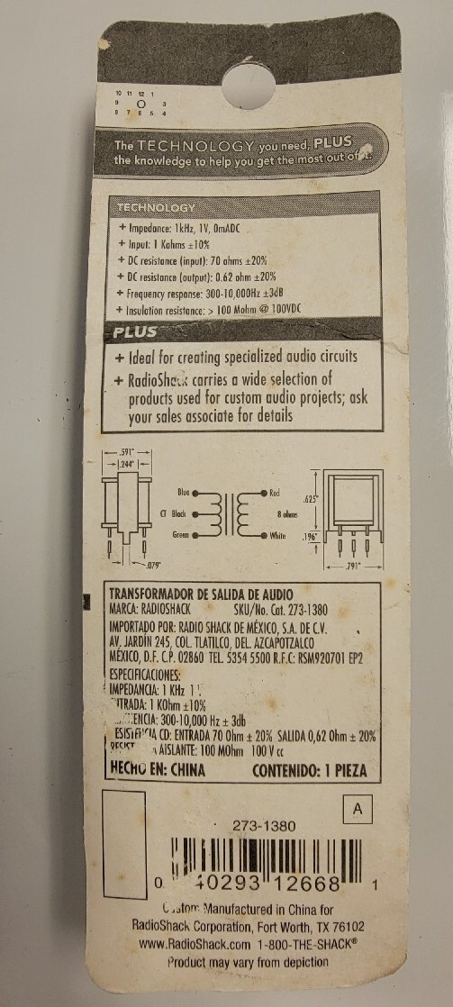
To add this feature to your Beige Box you will need a 0.47 µF 250V capacitor (non-electrolytic), an audio matching transformer: 8Ω-to-1 kΩ (RadioShack Part No. 273-1380 will be used in the example), a DPDT switch, and some wire. Refer to Figure 1.
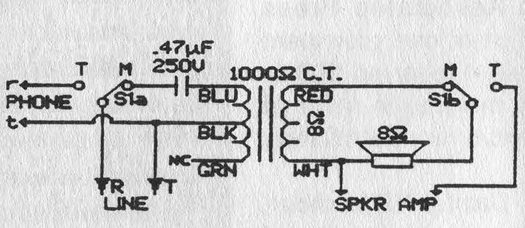
Figure 1
Open the phone. Locate the point where the line cord enters. The RED wire is the RING and is labeled R in Figure 1.
The GREEN (TIP) is labeled T. Points r and t (lower case) are the points where these connect to the phone circuitry.
Disconnect the RING from the phone circuitry and connect it to the center of one pole of the switch. Run a line from one leg to the point where the RING used to be.
Connect the capacitor to the other leg. Solder the other capacitor lead to the transformer's BLUE lead.
Connect the BLACK lead to the TIP. Ignore the GREEN transformer lead (cut it off if it annoys you). The high-impedance (1 kΩ) side is complete.
Now the low-impedance (8Ω) side:
Find the earphone leads. (If the colors give any clue as to polarity put the switch on the positive one.)
Connect the WHITE wire from the transformer to one of the speaker wires. Disconnect the other speaker wire from the main circuitry and solder it to the center of the free pole on the switch.
Attach the RED transformer lead to the leg on this pole which corresponds to the capacitor's position on the other pole, (i.e. the Monitor position). he remaining switch terminal should be connected to the point from which the speaker wire was removed.
With this modification the switch hook becomes somewhat pointless. The ringer can also be removed to make room for the transformer.
Test the switch, mount it, and label Talk and Monitor.
Many exciting new handsets of the Tone/Pulse switchable type have an extra switch: KEYPAD: IN/OUT
I assume this is to prevent accidentally dialing with your shoulder. This will not be discussed.
One last feature these new handsets have is a polarity test. This can be useful. Obtain one GREEN and one RED LED, an SPST momentary push-button, and a 1 kΩ resistor.
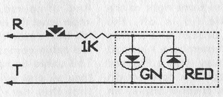
Figure 2
Refer to Figure 2. Connect the anode of the GREEN LED to the cathode of the RED one and to the resistor.
Tie the cathode of the GREEN to the anode of the RED and connect that to the TIP.
Connect the free end of the resistor to the button and the other side of the button to the RING.
Make sure that the cathode of the GREEN LED is wired to the BLACK alligator clip.
When the button is pressed, the GREEN LED will light if the RED clip is on the positive (+) and the BLACK clip on the negative (-). Note: The polarity test will create an off-hook status.
Thanks go to The Exterminator and The Terminal Man for their textfile, "Beige Box: Construction and Use" from May 1985, which detailed the construction reiterated in paragraph two.
The type of phone tap I employed in adding the Monitor mode was first brought to my attention in a textfile by The Phantom (title/date unavailable).
Note that if your speaker is not 8Ω you will have to use a different transformer; check with the outfit you get your 0.47 µF capacitor from.
Lastly, RadioShack no longer carries 0.47 µF capacitors. I wonder why? Other electronics distributors do. You may also find them in phone equipment isolating the ringer from the line. (Community Note: The 0.47 µF capacitor can be replaced with some 0.1 µF capacitors in parallel, what is important is the high-voltage and non-polarized rating as you don't know what's on the line.)