Product Review
Review by Les Inconnu (Sydney, Australia)
MoTron TDD-8 DTMF Decoder $99, MoTron Electronics 310 Garfield St. #4 Eugene, OR 97402 (503) 687-2118 |
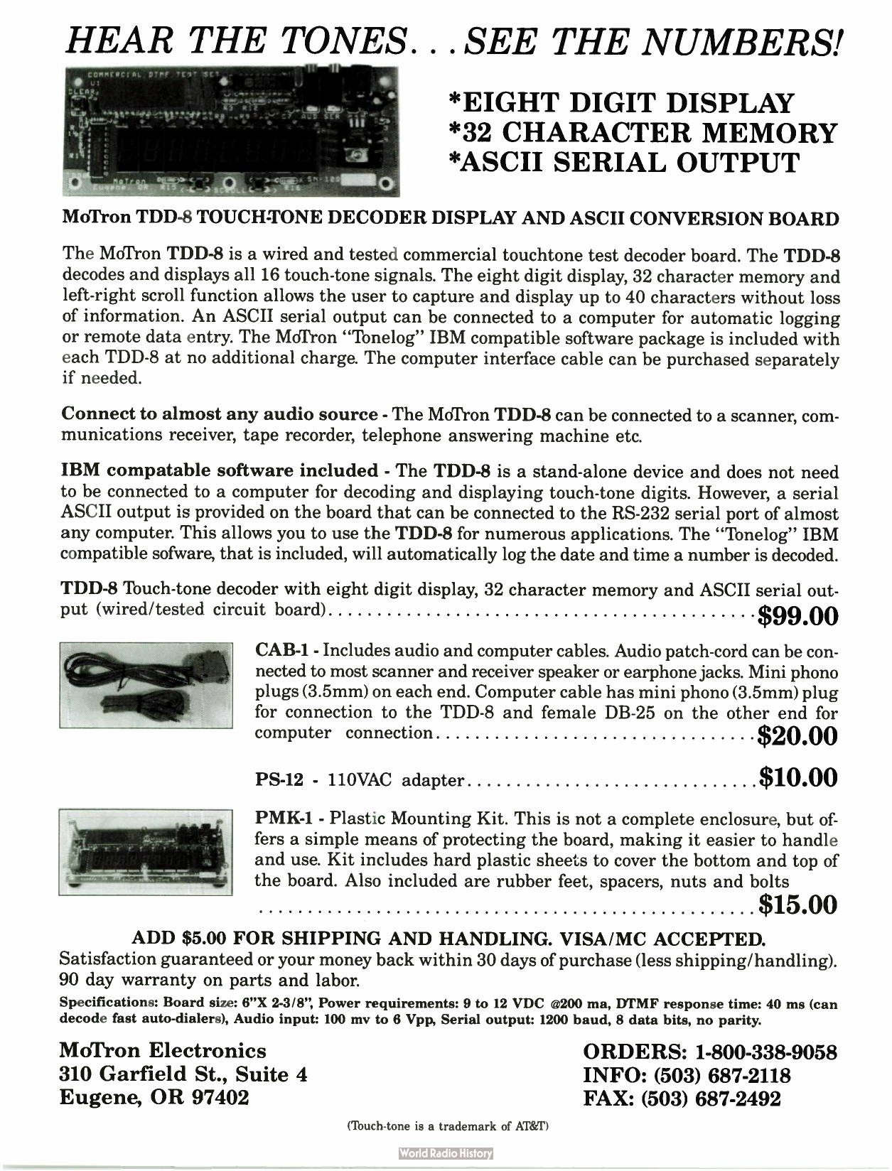
For some months now, Popular Communications has carried an advertisement for a "Touch-Tone Decoder/Display & ASCII Converter Board." As described, this device, the TDD-8, displays all 16 DTMF digits and provides an ASCII serial output. Input is accepted from any audio source: radio receivers, cassette recorders, answering machines: there is also IBM Logger software to decode and store the results.
Now something like this is sure to pique the interest of any phreak because it can be almost as important to decode DTMF tones as to generate them, but at ninety-nine dollars a throw (and U.S. dollars at that) plus extras, plus postage, it seems a little too expensive for mere curiosity. However, such a device has just found its way here to the far side of the planet, and it is indeed a very useful tool for exploring the telephone system.
First Contact
The package arrived from Oregon, airmail, in just two weeks. That in itself is worth mentioning when airmail delivery to Australia can take from five to twelve weeks. Very good service!
Not so good though was the documentation. The package contained a fully-assembled board, two cables, and a 5.25" disk. That's it! No documentation. No READ.ME file. Nothing!
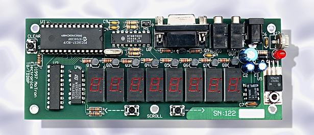
The board itself is a 150 mm x 60 mm double-sided PCB whose most noticeable feature is eight 7-segment LED displays. These display the digits decoded. The first digit appears in the right-most display, and automatically scrolls to the left as more digits are decoded.
A 40-pin chip with no markings other than "TDD-8" and a proprietary code, hand inked on a stick-on label, is obviously full of magic. The presence of a crystal on the board seems to indicate sampling techniques, as well as a shift register clock. Apart from a 7805 to turn the 12 volts into 5 volts, a green LED to indicate Power On, and some driver transistors and passive components, the board is bare.
Or almost bare. There are three miniature push-button switches: CLEAR, SCROLL <-, SCROLL ->
There are also three sockets: AUD, SER, and a concentric 2.1 mm power connector. The power connector proved to be center positive, outer negative (there is no standard for these things), however a protective diode has been installed across the input and this should keep the board from harm. A 2.5 mm connector will fit, with a little force.
The AUD and SER sockets take sub-miniature 3.5 mm (1/8") jack plugs. Two cables are provided at $20 (US) extra. One is a one meter long cord with two wires and 3.5 mm plugs at each end. One end sticks in the audio outlet of a radio receiver, such as a scanner and the other goes into the AUD input of the board. Obviously this carries the input signal.
The other cable has a 3.5 mm plug at one end, and this inserts into the SER outlet on the board. The other end of the cable has a DB-25 socket which attaches to COM1 or COM2 of your IBM backframe. The wiring for this cable is simple. Tip goes to pin 3. Sleeve goes to pin 7. Wire up both of these cables and save yourself twenty smackers.
A 120 volt AC to 12 volt DC converter is also available, but was not ordered, being of no use here where the power is 240 volts AC (and 260 volts AC in the west).
Setting It Up
Operation is very simple, in spite of the lack of instructions. Plug a 12 volt source into the power connector. The display flashes momentarily while the green LED lights up. The TDD-8 takes 75 mA with no display, 150 mA with all the displays lit. In their advertisements MoTron specifies 300 mA but 150 mA is the maximum, even while operating, so a battery supply would be easy. Eight alkaline C cells would be enough.
The AUD line will connect to a scanner audio outlet. "Ext Speaker" or "Record" provides sufficient voltage. Minimum input seems to be about 1.5 volts peak-to-peak in practice, while maximum is not known, (we were a wee bit cautious) but clipping seems to take place at 5.0 volts peak-to-peak. Just as the ad says, it is happy with the output of receivers, tape and cassette recorders, and answering machines.
Field Use
Now for all sorts of reasons, cost and fragility of the device being among them, we do not recommend that you hang one of these off a twisted pair with alligator clips. However, if you can put the TDD-8 into a suitable box it can be used, attached to a hand-held scanner or similar receiver. The box will need to have a transparent lid to read the display, attachments for the three switches, and three holes for the leads. You will have to work this out for yourselves. When used as a portable device only the AUD and power connectors are used. The TDD-8 holds 40-digits (rather than the 32 advertised) but it cannot tell where one sequence begins and ends. So if you have five 8-digit numbers, they will all run together as one big 40-digit number.
0 to 9 and A to D are all easy to read on the 7-segment display. # shows as three horizontal lines, one on top of the other, while * shows as a distorted S. It is easy to read with practice. The two SCROLL buttons let you scroll through the memory. CLEAR will clear everything.
Connecting to a PC
While almost any computer with an RS-232 connector and a dumb terminal program will receive something from the TDD-8, unless you write your own program it will not perform any better than the inbuilt display.
For IBM's (and compatibles), MoTron provides a 5.25" disk with a single file: TONELOG.EXE. When this is installed and the TDD-8 connected to COM1 or COM2 via the SER outlet the full power of this device is seen.
Run TONELOG.EXE and it first searches for the TDD-8. If it is not connected a bar (you couldn't call it a window) appears and tells you to connect it to COM1 or COM2. This is about as user-friendly as it gets, but then most of us won't be worried by this.
At the bottom of the screen is a two line menu. F1 to F4 and F6 to F11 all provide toggle switches. F5 is not used. F10 and F1 have no function, but all the others allow you to toggle between COM ports, switch the printer on and off, print, exit, or nominate a data file (PHONELOG.DTA is the default).
F7 brings up an empty window to let you set the alarms. However, there is no explanation as to how to do this, or even what alarms are. F8 toggles these mysterious alarms.
A sample PHONELOG.DTA is shown below. This file preserves exactly what appears, in real time, in the screen above the menu:
01-21-1993 21:35:10 11111111 1-111-1111 01-21-1993 21:35:20 22222222 01-21-1993 21:35:36 33333333 01-21-1993 21:35:46 1 01-21-1993 21:35:58 * 01-21-1993 21:36:36 7 01-21-1993 21:37:16 # 01-21-1993 21:37:17 0*789654411236687745887458*# 01-21-1993 21:50:45 5 Q1-21-1993 21:51:06 1234567890*# 01-21-1993 21:51:14 1234567890*# 01-21-1993 21:51:21 1234569877896541232*23321# 01-21-1993 21:51:37 8 01-21-1993 22:03:00 123456789012345678901234567890123456789012345678901234567890# 01-21-1993 22:04:00 1111111 111-1111 01-21-1993 22:04:11 22222222 01-21-1993 22:04:22 333333 01-21-1993 22:04:30 44444444 01-21-1993 22:04:41 5555555 555-5555 01-21-1993 22:04:49 66666666 01-21-1993 22:04:59 7777777 711-7777 01-21-1993 22:05:07 8888888 888-8888 01-21-1993 22:05:16 9999999 999-9999 01-21-1993 22:05:23 0000000 000-0000 01-21-1993 22:05:32 ******* 01-21-1993 22:05:41 # 01-21-1993 22.05:41 # 01-21-1993 22:05:41 # 01-21-1993 22:09:05 021234567 01-21-1993 22:09:19 00111239456753 01-21-1993 22:30:47 * 01-21-1993 22:31:10 *0987654321# |
Each line has the same form:
- Date as MM-DD-YYYY (e.g. 01-15-1993 for 15 January 1993). Obviously the product is aimed at the U.S. market, so it may just be a quibble to complain that the DD-MM-YYYY format that almost all the world uses is not an option. Still, it's annoying.
- Time as HH:MM:SS in a 24-hour clock.
- Digits as received.
- If you received seven digits, these are repeated in the form NNN-NNNN. If you received eight digits, these are repeated in the form N-NNN-NNNN, but not always. # is taken as an end-of-dial signal. A new line starts after every #. Any five-second pause is also taken as an end-of-dial signal.
We have not yet found any limit to the size of PHONELOG.DTA, but in practice you would want to keep it fairly small. If no # or five-second pause is found, then DTMF digits are recorded on the same line. There is no limit to this, but only the first 52-digits are saved to the file.
Radio Interference
As you would expect, there is some RF interference from the shift-register clock, especially from 7 to 35 MHz. This is only harmful if you sit the unshielded board next to a receiver. About 50 cm separation seems to cure it, but you may have to experiment.
Operation
Proper detection of DTMF tones depends on the signal-to-noise ratio received. This will depend on your radio link. We can envisage using the device to decode recordings made of tones sent by small transmitters, with the unattended receivers placed fairly close to the transmitters.
What More Can We Say?
The lack of documentation is a nuisance, but it can be coped with. A very interesting little device. One of the most useful we have seen. A pity that like a lot of good tools it's so expensive.
The DOS application "Logger" is provided with the Tone-Master ToneLogger DTMF Decoder Display Board and the Tone-Master TM-16a Plus DTMF and Rotary Test Decoder. Using the ToneLogger or the TM-16a Plus with your IBM/Compatible computer will allow you the flexibility of automatically logging each group of decoded digits with a date and time stamp. Logger can be configured to print each log entry as it occurs and the data file can be printed out at any time. The alarm feature can alert you when a specific sequence of digits is decoded. The log file is updated following each entry.
Logger arranges each log entry into four columns. The first two columns contain the date and time, the third column contains the digits as they are decoded, and the fourth column is used to display the digits as a telephone number, if applicable. For each line of data, Logger displays the current date and time. The time is updated every second until the first digit is decoded. As each digit is decoded, it is displayed and a five second timer is set/reset. When 5 seconds has elapsed without decoding another digit, or the # digit is decoded, the program processes that group of digits, then goes to the next line where the procedure is repeated.
(As the # key is often used in radio auto-patch, for terminating a call or hanging up a line if the wrong number is dialed, Logger assumes the number group is complete when it decodes this digit.)
Logger processes the decoded digits in the following order: First, if the Alarm feature is active, Logger looks for a match with the stored number groups. Second, Logger looks for a phone number format (any seven digits, or eight/eleven digits starting with the digit "1") and displays a conforming number group in the phone format in the fourth column. Third, if automatic printing is activated, the entire line is sent to the printer. Finally, the log file is opened, the entire line is stored at the end of the file, and the file is closed.
The data file generated by Logger is an ASCII text file, and can be opened in any text editor. The file can also be opened in any word processor that supports DOS text file import/export.