Build a DTMF Decoder
by Xam Killroy
When I saw the product review of the MoTron TDD-8 DTMF Decoder in the Summer 1993 issue of 2600, the last line got me thinking: "A pity that like a lot of good tools it's so expensive."
So I designed this decoder around the Teltone M-8870 DTMF receiver IC, the same part used in the MoTron TDD-8 product that was reviewed. Originally, I intended to make a tone decoder that would display the current digit and simultaneously send it out over a serial line. No problem, I thought. So I started bread-boarding it together, and soon realized it would actually take two shift registers, a stable clock generator, a custom burned PROM (to translate from four-bit binary to ASCII phone-pad symbols), and an RS-232 voltage level driver (because RS-232 voltages are different than TTL voltage levels).
"What I want," I thought in annoyance, "is a cheap computer to do all this conversion and communication and logging crap for me." And I had just such a thing sitting in my closet gathering dust. Years ago, the Commodore 64 was a very popular consumer computer, and there are millions of them floating around. They have a current street value of about $50, because they can't compare to any of the current computing muscle out there, but they are still enormously useful as a hacker's tool. They're durable, self-contained, and if you do blow one up experimenting, you don't feel nearly as bad as you would if you had just fried your $1400 486 or your $2000 Macintosh. And for bit manipulations and other "hacker applications," the Commodore 64 is actually much easier to use than a "real computer."
The Mac and PC are designed to be used by people who should never need to get to the guts of the computer. Running applications is easy. But if you want to write code, you need to get a compiler, write a source file, compile it, link it, and then run it. If you want to build your own I/O devices, you'd better be a very good hardware designer. But when you turn on a Commodore 64, you are immediately in a BASIC interpreter, and getting to machine level from there is not very difficult. If you want to read a memory value, you just PEEK at it from BASIC. And there are multiple I/O ports to play with, all very easy to get to.
In this article, I'll show you everything you need to build a stand-alone DTMF decoder, with a one digit display. You can even order all the parts as a kit (see sidebar) and solder it together in about 20 minutes. And then if you want all the logging capabilities of a much more expensive dedicated DTMF decoder, I'll show you how to interface this project to a Commodore 64, or even a VIC-20 computer (street value: about $10). With this DTMF decoder as an input device, you can decode and list Touch-Tones from any audio source, and you can even make other applications that use Touch-Tone control. With a telephone input, you can feed commands to your application remotely with a Touch-Tone phone. With a radio input, you can make an amateur radio repeater controller. The applications are limited only by your imagination.
Some people might look at this and say, why a Commodore 64? There are several reasons I chose this particular computer. It's easy to use, especially for these sorts of projects. Lots of people have them already, and if you don't have one you can probably pick one up at a garage sale (I've seen them for as little as $20). Please understand, I'm not advocating retrograde technology. There is no substitute for a Pentium when you're playing X-Wing or running crack on someone's password file, but there are also applications that don't need all that power, and with this project you can once again get use out of those "toy computers" which currently serve as door stops. If there is enough reader response to this project, I'll continue to design applications that you can add to your hacker's tool box. And perhaps these projects will also give you some ideas, so you can design and build your own custom tools.
Of course, if you don't have and don't want to use a Commodore 64, and you know enough about the hardware interface, you can always hook this DTMF decoder to any computer of your choice, even a PC or Macintosh. The operation and outputs are explained below. The rest is left as an exercise to the reader.
Circuit Description
This section is for anyone who really wants to know what every part of the circuit is doing. If you don't really care, this is isn't vital and you can skip to the next section, "Circuit Construction."
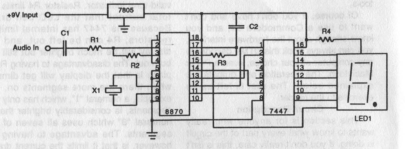
Figure 1: Circuit Schematic
The schematic diagram for this project is shown in Figure 1. The three major components are the DTMF receiver IC (IC1), the display driver IC (IC2), and the seven-segment LED that displays the current digit. All the other parts provide power, support, and input conditioning for the circuit.
The capacitor in the audio input path (C1) is to block any DC in the audio input signal. The resistors (R1 and R2) form the audio amplifier feedback loop, which in this circuit (R1 & R2 = 100kΩ) sets the gain of the internal differential input amplifier in the M-8870 to unity. The crystal used by IC1 to generate its internal clock (X1) is a standard 3.58 MHz color-burst crystal. Finally, R3 and C2 form an RC timing delay that determines how long a tone must be present on the input to be considered valid, and then how long it must be off before the next tone is considered a "new" tone. With the values chosen here (R3 = 330kΩ, C2 = 0.1 µF), the time for a tone to be considered valid is about 40 milliseconds.
The four-bit decoded output of the M-8870 goes to a seven-segment decoder/driver, which is IC2, a 7447. The use of an off-the-shelf part like the 7447 is convenient and cheap, but provides one problem: the decoder IC doesn't output a binary 0 for an input Touch-Tone digit of "0". Furthermore, all the other non-numeral digits (#, *, A, B, C, D) are also rendered as symbols by the decoder IC. See "Circuit Operation" section below.
The 7447 drives a common anode seven-segment display on which the decimal point serves as a power-on and valid-tone indicator. Resistor R4 limits the total current that the LED can draw. Because the 7447 has internal limiting resistors, R4 can be left out, and the display will be much brighter but still not burn out. The disadvantage to having R4 in place is that the display will get dimmer when there are more segments on.
For example, a numeral "1", which has only two segments, is considerably brighter than a numeral "8" which uses all seven of the segments. The advantage to having R4 however, is that it limits the current drawn by the entire circuit and makes the total current drain more uniform over time. This is particularly useful if you intend to power the circuit from the host computer bus, where current drain may be an issue (see "Computer Interface" section).
When operating without power from the host computer, or in a stand-alone configuration, power is provided to the circuit by a voltage regulator (IC3) which sources 5V from any input voltage between about 7.5V and 20V. The circuit is intended to be used with a 9V battery (attached to CON1).
Circuit Construction
You will need several tools to begin: wire cutters, wire strippers, a low-wattage soldering iron, and some rosin core (not acid core) solder. You will also want a heat sink (such as an alligator clip), and a well-lighted workspace where you can drip solder.
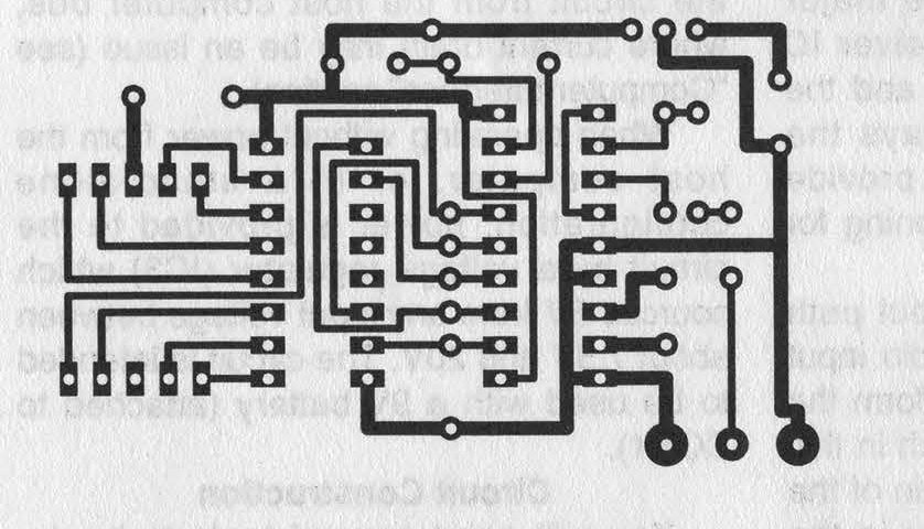
Figure 2: Printed Circuit Board Artwork
The entire circuit can be build on a single-sided printed circuit board 45 mm x 65 mm. The artwork for the board is shown actual size in Figure 2. This shows the copper traces as they should actually appear on the underside (opposite from component side) of the circuit board. The best way to fabricate the circuit board is photographically, but walking through the entire process of etching and drilling circuit boards is beyond the scope of this article. Because there are traces running in between IC pins on this board, the layout tolerances are fairly tight. If you have never made a printed circuit board before I strongly suggest you purchase the pre-fab board, or the entire kit (see sidebar). The circuit is also simple enough that you can assemble it on perf-board, using the schematic in Figure 1, without the printed circuit board, but it won't be as durable or reliable.
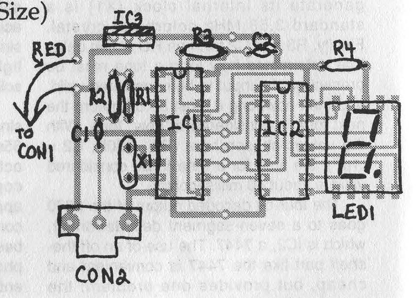
Figure 3: Component Layout Guide
The component layout on the top (blank) side of the circuit board is shown in Figure 3. Insert each component in the board, and then solder it in place and trim its leads off. It's easiest if you begin with the resistors, because the board can rest on them while you solder them in place. The rest of the components can then be inserted in order by height, from shortest to tallest, starting with IC1 and IC2, and ending with the voltage regulator (IC3).
Make sure that the board surface is clean before you begin soldering. Rubbing it down with rubbing alcohol and then wiping off any excess will insure that there is no grease from your fingers. When you solder the parts, remember that the components, particularly the ICs and the LED, are susceptible to thermal damage if you get them too hot. This means that you should use a heat sink (such as an alligator clip connected on the component side) on the leads of the ICs as you solder them. You should make sure that you only apply the soldering iron to the component leads for the minimum time needed to get a good clean solder joint.
Also make sure that you get the ICs in the board with the correct orientation. They will fit in two different directions, but you must have the end with the notch toward the edge of the board with the voltage regulator. The voltage regulator also has only one correct orientation, which is with the front (the labeled side) facing toward the ICs and the metal tab facing the edge of the board. If you put it in backwards, the circuit will not work. The decimal point on the seven-segment display should be toward the edge of the board. Make sure you put the RED lead on the battery connector (CON1) in the hole closer to the voltage regulator (IC2). If you are not certain of the correct orientation of any of these parts (IC1, 1C2, 1C3, LED1, or CON1), study Figure 3 and make sure you have them oriented correctly before you solder them in place.
When the circuit is finished, there should be seven unfilled holes between IC1 and IC2 (which is where the computer interface is connected, see below).
Circuit Operation
Once you have built the circuit, turn it on by connecting the 9V battery. The decimal point on the LED should light up. You're now ready to decode DTMF tones. Connect a tone source to the audio input. When the circuit receives a "valid" Touch-Tone, it displays the value on the seven-segment display. When a valid tone is applied to the input, the decimal point will turn off. Once a tone has stopped, the decimal point will light again, and the number will remain on the display until the next valid tone is received.
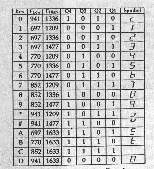
Table 1: Keys, Frequencies, Decoder Outputs, and Displayed Symbols
One quirk of using an off-the-shelf display driver (the 7447) with the M-8870 DTMF receiver is the way a Touch-Tone "0" is displayed. Because the M-8870 doesn't output a binary 0 for the tone "0", it is actually displayed as one of the non-numeral symbols. A Touch-Tone "D" is what is displayed as a "0" on the seven-segment LED. Table 1 shows all of the Touch-Tone inputs, their binary outputs, and the symbol displayed on the seven-segment LED for each.
Computer Interface
Although this tone decoder can be used as a stand-alone device, it is difficult to catch multiple digits, because they are only displayed on the seven-segment display until the next tone comes along. Furthermore, if the same Touch-Tone digit is received twice in a row, the only way you will tell from looking at the display is by seeing the decimal point blink off as the next valid tone arrives while the number or symbol displayed remains the same.
This decoder becomes really useful when you hook it to something that can record the digits as they occur, and keep them in memory or display them to a multi-digit display (like a screen). All we need is a computer with a binary input port. For this project, I used the user port on the Commodore 64. This is the card edge on the far right as you look at the back of the computer. The six holes on the decoder circuit board between IC1 and IC2 are where you connect the board to the user port. The seventh hole (at the top of the decoder) is an auxiliary power input, if you want to power the decoder circuit from the computer (and eliminate the need for batteries).
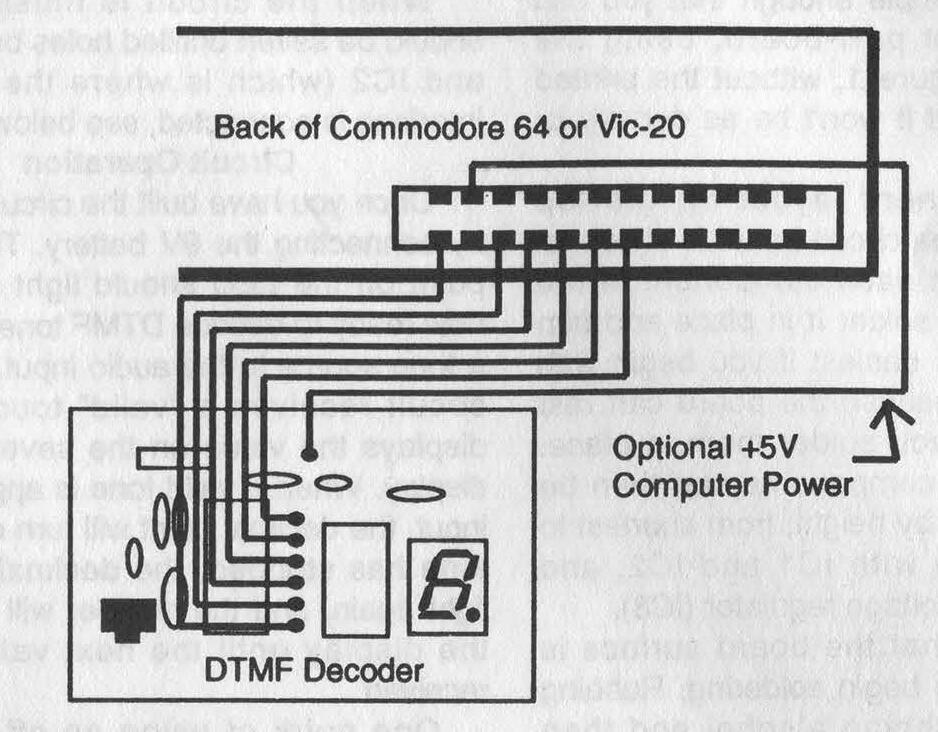
Figure 4: Commodore 64/VIC-20 Interface
Figure 4 shows which pins on the connector are connected to which holes on the board. The bottom-most hole on the board is the ground connection, the middle five holes are the four bits of the decoded digit and the valid bit. By connecting them to the user port, the state of the DTMF decoder is now reflected by the user port data byte in the computer's memory.
The algorithm for reading a digit in from the DTMF decoder is pretty straightforward. We just keep "polling" (checking the value of) the user port. If the valid bit is low (0), we check again. We look until the valid bit goes high (1), and then we record the current digit from the four-bit binary input. Then we wait for the valid bit to go low again before we start the whole process over.
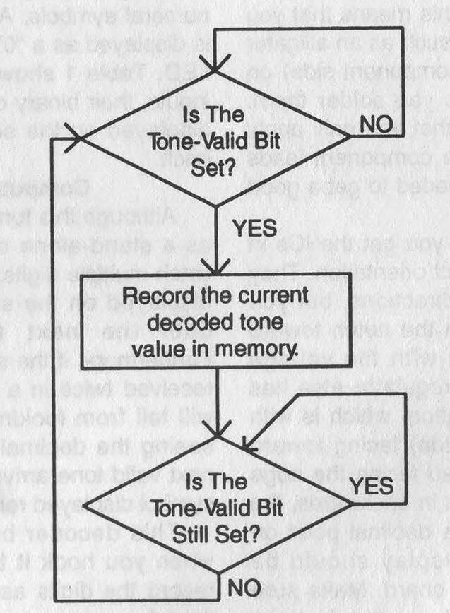
Figure 5: Flowchart of Simple Decoder Polling Algorithm
Figure 5 shows a flow-chart of this process. The Commodore 64 is a very slow computer by current standards, but it is still blazingly fast compared to the speed that DTMF digits can arrive. So a program written even in the glacially quick language of BASIC is plenty fast for our needs.
Figure 6 - Commodore 64/VIC-20 Sample Code
10 GOSUB 10000: REM INITIALIZE VARIABLES 20 GOSUB 5000: REM SET FOR COMPUTER TYPE 30 GOSUB 4000: REM INITIALIZE THE PORT 100 REM MAIN PROGRAM LOOP 110 GOSUB 1000: REM GET A DIGIT 120 GOSUB 2000: REM PRINT DIGIT TO SCREEN, UPDATING LAST DIGIT TIME 130 GOSUB 3000: REM WAIT FOR THAT TONE TO END 140 GOTO 100: REM CONTINUE MAIL LOOP 1000 IF PEEK(DREG) AND 16 THEN GOTO 1020 1010 GOTO 1000: REM LOOP UNTIL VALID BIT GOES HI. 1020 DTMF=PEEK(DREG) AND 15 1030 RETURN 2000 IF TIME-LAST > 180 THEN PRINT 2010 PRINT OUT$(DTMF); 2020 RETURN 3000 IF PEEK(DREG) AND 16 THEN GOTO 3000 3010 LAST=TIME 3020 RETURN 4000 POKE DIR, 0: REM SET ALL BITS TO INPUT 4010 RETURN 5000 IF (FRE(0)-(FRE(0)<0)*65536)<5000 THEN GOTO 5040 5010 DIR=56579: REM DATA DIRECTION REGISTER ADDRESS FOR COMMODORE 64 5020 DREG=56577: REM USER PORT DATA ADDRESS REGISTER FOR COMMODORE 64 5030 RETURN 5040 DIR=37138: REM USER PORT DATA ADDRESS REGISTER FOR VIC-20 5050 DREG=37136: REM USER PORT DATA ADDRESS REGISTER FOR VIC-20 5060 RETURN 10000 DIM OUT$(16): REM DIMESIONS OUTPUT SYMBOL ARRAY 10010 READ CODE,SYMBOL$ 10020 OUT$(CODE)=SYMBOL$ 10030 IF CODE <> 15 THEN GOTO 10010 10040 LAST=0: REM TIME LAST TONE ENDED 10050 DTMF=0: REM DECODED DTMF VALUE 10060 DREG=0: REM DATA ADDRESS REGISTER 10070 DIR=0: REM DATA DIRECTION ADDR. REG. 10080 RETURN 15000 REM DATA FOR EACH POSSIBLE DTMF INPUT AND IT'S CORRESPONDING SYMBOL 15010 DATA 0,"D",1,"1",2,"2",3,"3",4,"4",5,"5",6,"6",7,"7",8,"8",9,"9",10,"0" 15020 DATA 11,"*",12,"#",13,"A",14,"B",15,"C" |
The sample program in Figure 6 is a DTMF number logging program. It scans for digits. If a digit is received, it prints it to the screen and waits for the next digit. If it gets a whole stream of digits, it will print them all on the same line. If it gets a "#" sign, or if there is a delay of more than three seconds until the next digit, it will skip to the next line and print any subsequent digits there. Numbers are not stored in memory, so once they scroll off the top of the screen, they are lost.
The code for the BASIC number logging program is broken down into subroutines and commented to indicate what is happening where. You can use this as a guide to writing your own code, or you can just copy sections of this program into your own. The possibilities of what you can do with this are limited only by your imagination. It's up to you.
And now you have a DTMF decoder. It's cheaper than an equivalent commercial product, and it offers a chance to start your own hacker's tool kit, in the spirit of the earliest pioneers who built all their own equipment. Good luck and have fun.
Sidebar
Part List, Kit Ordering Information
Many of the parts for this kit are available at RadioShack, and have RadioShack part numbers in parentheses next to them. The rest are fairly common and can be found at electronic hobby supply stores or from parts distributors. I've also contracted with Millennium Systems to provide all the parts and the printed circuit board in kit form. They also sell just the printed circuit board, if you prefer.
R1, R2: 100 kΩ (271-1347)
    R3: 330 kΩ (This part value can be varied widely, so you can substitute at 470 kΩ resistor,
                  RadioShack part number 271-1354)
    R4: 330 ohm (271-1315)
C1, C2: 0.1 microfarad (272-1069)
    X1: 3.58 MHz color-burst crystal
  LED1: Common-anode seven-segment LED
   IC1: Teltone M-8870-1 DTMF Receiver (You can call Teltone at 1-800-426-3926 to find your nearest distributor.)
   IC2: 7447 display decoder IC (276-1805)
   IC3: 7805 +5V regulator IC (276-1770)
  CON1: 9V battery clip (270-325)

Optional

  CON2: Female RCA phono plug for audio input (274-346, but this is not the printed circuit board mounted part that
                                               the circuit board art is designed for)

  CON3: 24-pin (12-pin/side) card edge connector, 0.156" spacing (for connection to the Commodore 64 User Port)
|
Printed Circuit Board and DTMF Decoder Kits
Printed Circuit Board Only - $15
Complete DTMF Decoder Kit (Circuit board, components, and CON1 & CON2) - $28
Complete Kit + 24-Pin Card-Edge Connector for C-64 or VIC-20 User Port (CON3) + 5.25" Disk with number logging software - $42
Send orders, payable to:
P.O. Box 70868
Sunnyvale, CA 94086
You can also send comments and feedback to this address. If you have an application you'd like to see added to the hacker's tool kit, send it in.
Code: dtmf.bas