Building a Red Box
by J.R. "Bob" Dobbs
Essentially, the Red Box is a device used to fool the phone company's computer into thinking coins are deposited into a payphone. Every time you drop a coin into a payphone, the phone signals the type of coin inserted with one or more bursts of a combination of 1700 Hz and 2200 Hz. The tone bursts are coded as follows:
Nickel: One 60 millisecond pulse
Dime: Two 60 millisecond pulses separated by 60 milliseconds
Quarter: Five 35 millisecond pulses separated by 35 milliseconds
How to Use It
Operation is simple. Simply dial a long-distance number (some areas require you to stick in a genuine nickel first), wait for the ACTS computer to demand your cash, and press the "DEPOSIT" button on the Red Box for each coin you want to simulate.
The coin signals are coupled from the Red Box into the phone with a small speaker held to the mouthpiece.
For local calls, either you must first deposit a genuine nickle before simulating more coins or place your call through the operator with: 0+XXX+XXXX
Use some care when the operator is on the line - sometimes they catch on to your beeper ploy.
Circuit Operation
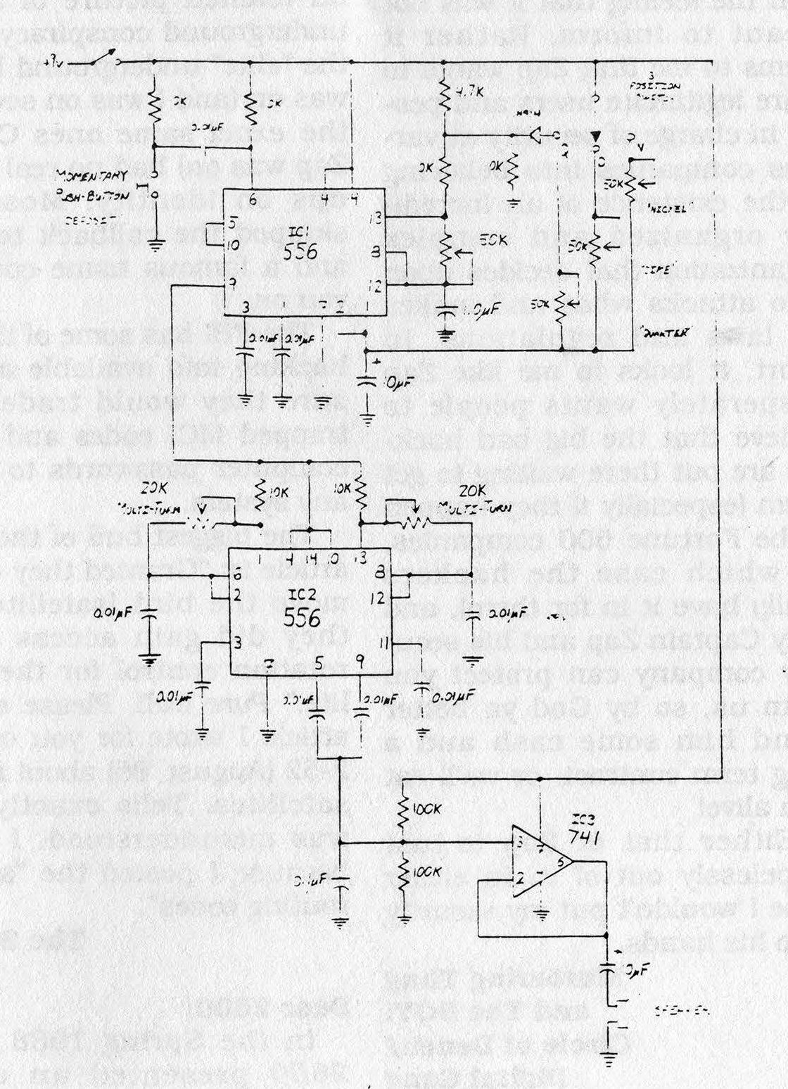
Each time the push-button is pressed, it triggers half of IC1, configured as a monostable multivibrator to energize the rest of the circuit for a length of time determined by the setting of the coin selector switch. This in turn starts the other half of IC1, configured as an astable multivibrator, pulsing on and off at regular intervals at a rate determined by the 50 kΩ pot between pins-12 and --13.
The output of the astable thus alternately powers of IC2, configured as a square wave oscillator, providing the required 1700 Hz and 2200 Hz to the op-amp which acts as a buffer to drive the speaker.
Construction
Assemble the circuit as you wish. Component placement is not critical. I found the easiest method was to use point-to-point wiring on a "universal" PC grid board with solder ringed holes. Use sockets if you aren't a whiz with a soldering iron. Be sure to leave easy access to the potentiometers for alignment.
Alignment and Testing
For alignment, a frequency counter and triggered sweep oscilloscope are extremely handy (but not absolutely necessary).
Install a temporary jumper from +9V supply to pin-14 of IC2 and temporarily disconnect the 0.01 µF capacitors from pins-5 and -9 of IC2. Power up the circuit. Measuring the output from pin-5 of IC2 with the frequency counter, adjust the 20 kΩ pot between pins-1 and -6 for an output of 1700 Hz.
Now adjust the 20 kΩ pot between pins-8 and -13 for an output of 2200 Hz from pin 9 of IC2.
Remove the temporary jumper and re-attach the capacitors to pins-5 and -9. (Note: If no frequency counter is available, the outputs can be adjusted by ear one at a time by zero-beating the output tone with a computer generated tone of known precision.)
Next, temporarily disconnect the wire between pins-5 and -10 of IC1. Set coin selector switch in the "N" (nickel) position. With the oscilloscope measuring the output from pin-9 of IC1, adjust the 50 kΩ pot between pins-12 and -13 of IC1 for output pulses of 60 millisecond duration.
Reconnect the wire between pins-5 and -10. (Note: If no scope is available, adjust the pulse rate by ear using computer generated tones for comparison.)
The remaining adjustments are made by ear.
Leave the selector switch in the "N" position. Adjust the 50 kΩ pot labeled "DIME" for a quick double beep each time the push-button is pressed.
Finally, set the selector to "QUARTER". Adjust the 50 kΩ pot labeled "QUARTER" until exactly five very quick beeps are heard for each button press. Don't worry if the quarter beeps sound shorter and faster than the nickel and dime ones. They should be.
Conclusion
If all went well to this point, your Red Box should be completely aligned and functional.
A final test should now be conducted from a payphone using the Dial Access Test Line (DATL) coin test. Dial 0-959-1230 and follow the computer instructions using the Red Box at the proper prompts. The computer should correctly identify all coins "simulated" and flag any anomalies.
With a little discretion, your Red Box should bring you many years of use. Remember, there is no such thing as spare change!
Parts List for Red Box
 Semiconductors
2   556 Dual-Timer ICs
1   741 Op-Amp IC
1   1N914 Diodes

Resistors
6   10 kΩ Resistors
1   4.7 kΩ Resistor
2   100 kΩ Resistors
4   50 kΩ PCB-Mount Potentiometer
2   20 kΩ Multi-Turn Potentiometer

Capacitors
10  0.01 µF
 1  1.0 µF Electrolytic
 2  10 µF Electrolytic

Miscellaneous
2   14-Pin DIP Socket
1   8-Pin DIP Socket
1   Momentary Push-Button Switch (N/O)
1   SPST Toggle Switch
1   Speaker or Telephone Earpiece
    Perf Board
    Box
    Mounting Hardware
    9V Battery Clip
|