Converting a Tone Dialer into a Red Box
by Noah Clayton
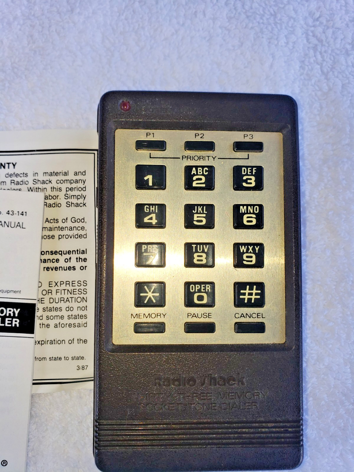
A very simple modification to RadioShack Pocket Tone Dialer (Part No. 43-141) can make it into a Red Box.
The modification consists of changing the crystal frequency used to generate the microprocessor's timing. To make this modification you will need a Phillips screwdriver, a flat-bladed screwdriver, a soldering iron, a pair of long-nose pliers, a pair of wire cutters, and a 6.5536 MHz (megahertz) crystal.
Orient the dialer with the keypad down and the speaker at the top. Remove the battery compartment cover (and any batteries) to expose two screws. Remove these two screws and the two on the top of the dialer near the speaker. There are four plastic clips that are now holding the two halves of the dialer together. Push on the two bottom clips near the battery compartment and pull up to separate the bottom part. Now slide a flat screwdriver into the seam on the left starting from the bottom and moving towards the top. (You may have to do this on the right side as well.)
When the two halves separate, slide the speaker half underneath the other half while being careful not to break the wires connecting the two. Locate the cylindrical metallic can (it's about half an inch long and an eighth of an inch in diameter) and pull it away from the circuit board to break the glue that holds it in place. Unsolder this can, which is a 3.579545 MHz crystal, from the circuit board.
The hard part of this modification is getting the new crystal to fit properly. Bend the three disk capacitors over, as indicated on the diagram, so that there will be room for the new crystal. Also remove the indicated screw. Since the 6.5536 MHz crystal you have is probably much bigger than the crystal you are replacing, you will need to bend the leads on the new crystal so that they will match up with the pads on the circuit board. Place the new crystal on the circuit board using the diagram as a guide. Solder the new crystal in place. As an added touch, you might peel the QC sticker off of the PC board and place it on top of the crystal. Now carefully snap the two halves back together while checking to make sure that none of the wires are getting pinched or are in the way of the screw holes. Put the case screws back in and insert three AAA batteries into the battery compartment.
Your dialer is now ready to test. Switch the unit on. The LED on the dial pad side should be lit. Set the lower slide switch to STORE mode. Press the MEMORY button on the dial pad. Press the * key five times. Press the MEMORY key again and then press the P1 key. A beep tone should be heard when any key is pressed and along beep should sound after the P1 key has been pressed to indicate that the programming sequence was performed correctly.
Switch the unit into DIAL mode. Press the P1 key, and five tone pulses that sound remarkably like coin tones should come out of the speaker. I usually program P1 to be four quarters (insert one or two PAUSEs between each set of five tones), P2 to be two quarters, and P3 as one quarter.
Of course, you can no longer use the unit to generate Touch-Tones.
History and Theory
A friend of mine and I were sitting around his house one day trying to come up with away to build a reasonable Red Box. I had built one with analog sine wave generators in the past, but it was difficult to adjust the frequency of the outputs and keep them accurate over time and with changes in temperature. The electronic project box I had assembled it in was bulky, hard to conceal, and definitely suspicious-looking.
My friend was playing with his calculator while I was wishing that we had the money and time to design a microprocessor-controlled device with its own custom PC board. After a while, he announced that he had an idea. He had been looking at a data sheet for a Dual-Tone Multi-Frequency (DTMF) (a.k.a. Touch-Tone) generator chip. He calculated the ratio of the coin tone frequencies of 1700 Hz and 2200 Hz to be 0.7727. He then went through all of the tone pairs used for DTMF, calculating each of their ratios.
He discovered that the ratio of the tone pair used for * was very close to the ratio for the coin tone frequencies. This ratio, 941 / 1209 = 0.7783, differed from the coin tone ratio by less than one percent.
What this meant was that since the tones generated by such a chip are digitally synthesized from a divider chain off of a reference crystal, if one changed the reference crystal to the "right" frequency, the coin tones would be generated instead of the DTMF *.
Most DTMF chips use a TV color-burst crystal with a frequency of 3.579545 MHz. To determine the crystal frequency that would generate the coin tones, one would compute:
3,579,545 / (941 * 1700) = 6,466,766 MHz 3,579,545 / (1209 * 2200) = 6,513,647 MHz (6,466,766 + 6,513,647) / 2 = 6,490,206 MHz |
Unfortunately, this is not a standard crystal value and getting custom crystals made is a real pain for the hobbyist. The closest standard frequency I could find was 6.5536 MHz. I tried a crystal of this value and it worked.
(The actual frequencies produced by a DTMF generator chip depend on the particular manufacturer's design. The color-burst crystal's frequency is divided down to the DTMF tones by an integer divider chain. Because the color-burst crystal's frequency is not an integer multiple of the DTMF tones there will be a small difference in the frequencies produced from the standard.)
When we first tried this, we were using one of RadioShack's earliest tone dialers. It consisted of a DTMF generator chip only, and as such could not produce a sequence of tones automatically. Tones were generated as long and as fast as one could press the buttons. We were able to simulate nickels using this device but doing so was fairly slow and tedious. Because our manual timing was so far off of the mark, our attempts at producing dime or quarter signals were a miserable failure. A live operator would be instantly connected to the line whenever we tried it.
The Shack's next model had a microprocessor and a tone generator in it, each with separate crystals controlling their respective timing. It was just a matter of changing the micro's crystal to get the right on-off timing for a quarter's timing for a quarter's tone sequence as well as the tone generator's crystal to get the proper coin frequencies.
Later RadioShack came out with the model used in this project. I promptly bought one because it was lower cost and more compact than their older model. I put some batteries in it and tried it out. It generated DTMF sequences with very long on and off times, but other than that, seemed like a nice unit. Upon disassembling it though, I became unhappy. There was only one crystal. It controlled the timing for a microprocessor that was specifically designed to synthesize DTMF. There was no way to independently adjust the output frequency of the tones from their on-off timing.
I was just about to say, "Oh well, yet another tone dialer for my collection" when it hit me. Why not try the higher frequency crystal? The timing might come out close enough to simulate either a quarter or a dime. I made the mod and tested it out. It worked!
Thank you RadioShack, for giving us a convenient to use, easily concealable and non-suspicious looking Red Box.
Reference
The crystal is available from Fry's Electronics in Freemont, CA for $0.89 plus the charge for UPS Red or Blue. Their number is 415-770-3763. I would suggest buying five, some for future use and some just in case you cut the leads too short when trying this project.
Coin Frequencies: 1700 Hz and 2200 Hz (+/- 1.5%)
Timing: 5 cents, one tone burst for 66 ms (milliseconds) (+/- 6 ms); 10 cents, two-tone bursts each 66 ms, with a 66 ms silent period between tones 25 cents, five-tone bursts each 33 ms (+/- 3 ms) with a 33 ms silent period between tones.
43-141 - This is the original 33 memory pocket tone dialer. This model was brown and very ugly-1970's looking compared to the newer models. This one will work for Red Boxing just as good as the new ones. RadioShack stopped making this model in 1994.
43-145 - This is a cheap tone dialer with no memory presets on it. These dialers cost $16.99 and can be modified, but without the memory presets you won't be able to make quarter tones, just nickels which can be a little time-consuming. But if you want to save a lousy 10 bucks, this is the way to go.

43-146 - This is the current 33 memory tone dialer which sells for $24.99. Both the newest "hack-proof" model and the 1995-model share the same catalog number, contrary to popular belief. The crystal in this model has been disguised to trick people into thinking that you can no longer use it for illegal purposes.