Motorola Bag Phone Handset Control
    EXPERIMENTAL    

Overview

An experimental control circuit to simulate the handset key presses on an old Motorola "bag"-style cellular phone.  Refer to GBPPR 'Zine, Issue #4 for an application on using two old cellular phones to jam tape recorders.

A standard Microchip PIC16F84 is used to control two 4066 quad bilateral switches, which in turn, simulate pressing the keys on the keypad.  Wires are run from the 4066s to each row and column on the handset's keypad.  When a connection is made from the row to the column, the phone registers a key press.  The source code for the PIC16F84 is written in PICBasic, so it's very easy to understand.  The code, as written, takes about ten seconds to execute.

For this design, you'll only need to control the keys: 1, 2, 3, 7, 8, 0, and #

The key sequence will be like this:

  1.   [#]  - Enter the test mode's servicing level.
  2.   [1] [1] [0] [0] [0] [1] [#]  - Enter channel '0001' for a transmit frequency of 825.03 MHz.
  3.   [2] [8] [#]  - Enable the high tone of 1,150 Hz.
  4.   [3] [0] [#]  - Enable the low tone of 770 Hz.
  5.   [1] [2] [0] [#]  - Set the maximum transmit RF power of 3 Watts.
  6.   [2] [7] [#]  - Continuously transmit control channel data.

This makes a nice "warbly" jamming noise signal, useful for jamming tape recorders.

Keypad Connections

            Column

            C1   C2   C3
         +---------------+
Row   R1 |  1    2    3  |
         |               |
      R2 |  4    5    6  | (R2 is not used in this design)
         |               |
      R3 |  7    8    9  |
         |               |
      R4 |  *    0    #  |
         +---------------+

Construction Notes & Pictures

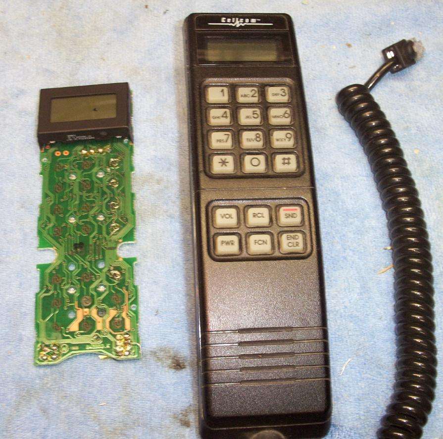
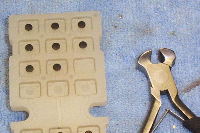
Handset overview.  An example keypad circuit board is shown on the left.

Taking the handset apart.  There are usually three screws, two T6 Torx and a T8 Torx.

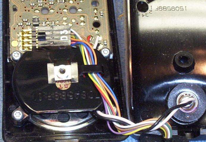
Close up picture of the microphone (right), speaker, and handset cable connector.

The pinout and wire color for the RJ-45 connector is as follows:

  1. BLUE  - Handset Logic Ground
  2. RED  - +9.5 VDC
  3. PURPLE  - T-DATA, 3-Wire Databus "True"
  4. ORANGE  - C-DATA, 3-Wire Databus "Complimentary"
  5. YELLOW  - R-DATA, 3-Wire Databus "Return"
  6. BROWN  - Handset Audio Ground
  7. GREEN  - No Connection
  8. WHITE  - Receive Audio to Handset

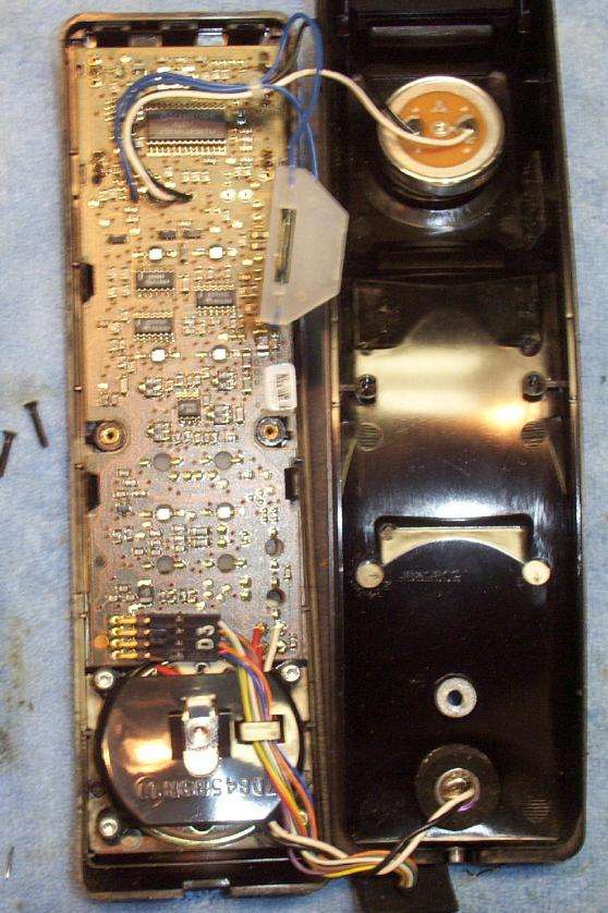
Internal view.  Clear out all the nonsense.

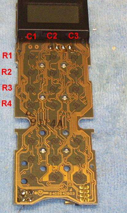
Close up of the keypad and its connections.  We'll only be interested in the twelve top pads.  Note the three columns (going up and down) and the four rows (going across).  We'll number the columns C1, C2, and C3 and the rows R1, R2, R3, and R4.

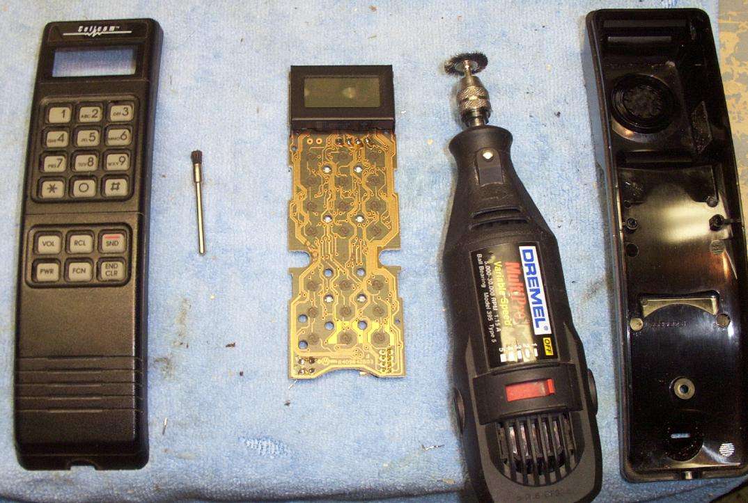
To remove the solder mask on the circuit board (to make testing with a continuity meter easier), use a Dremel tool with a wire brush attachment.

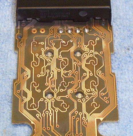
Close up picture of the keypads with the solder mask removed.

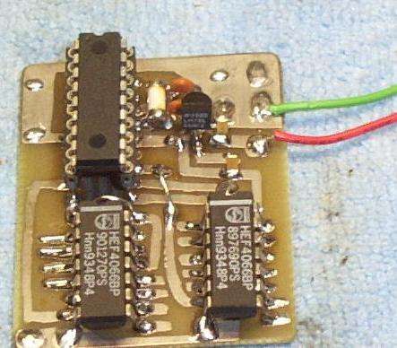
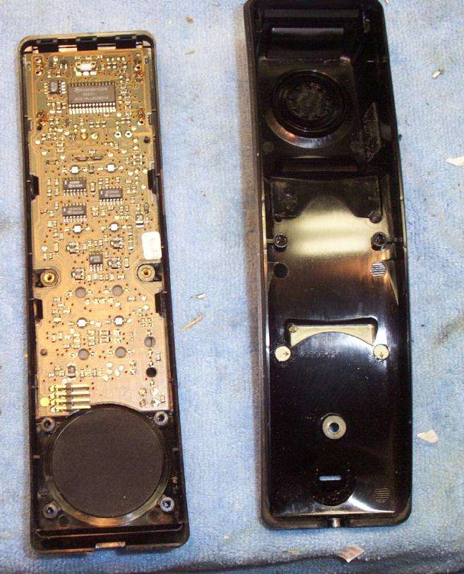
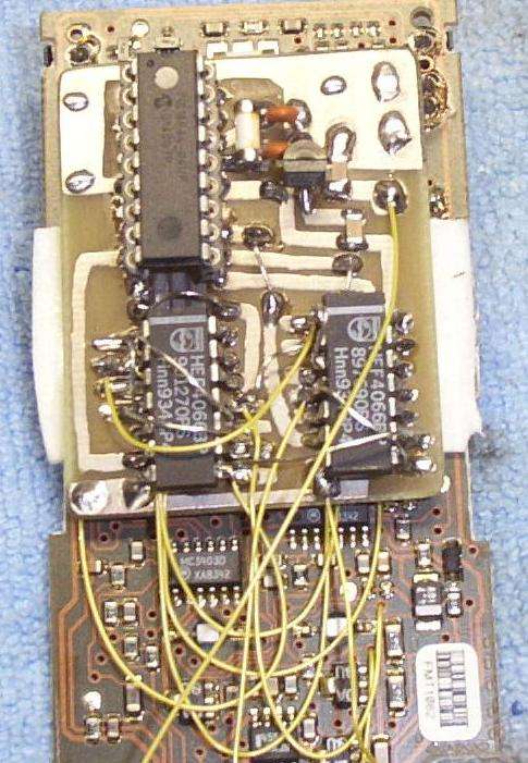
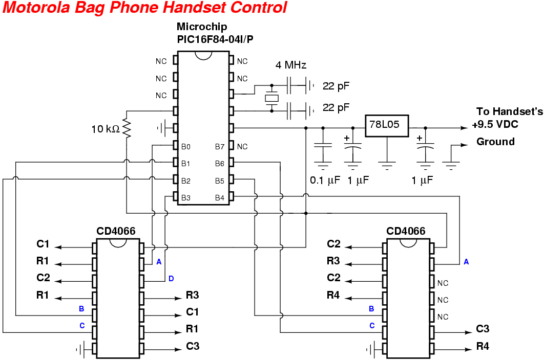
Control circuit board.  PIC16F84 is on the top left, the two 4066s are on the bottom.

You may want to remove the little conductive pads behind the rubber keys.  This will help prevent any accidental key pressing during operation.

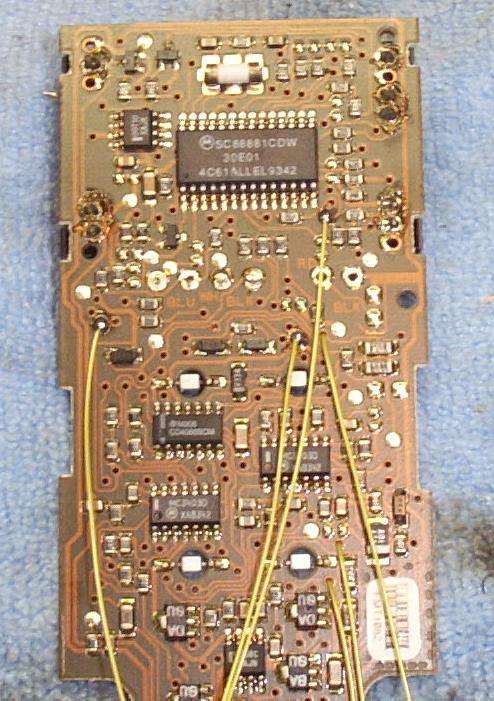
Installation of the three row wires and the three column wires.  You'll have to pin them out to double check them.  Yes, it's a pain.  Have fun!

Installation is complete.  This was an experimental version, so it's a little messy.

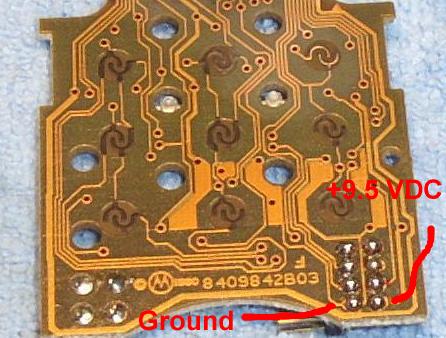
Power the circuit from the +9.5 VDC line on the handset connection.  

Schematic & PIC Source Code


Knowledge is Power

GBPPR Projects