But what happens if it is desired to reprogram a device which has been soldered into an application circuit? Is it necessary to remove the device for reprogramming or is there some way to re-program it in place?
Requirements for In-circuit Re-programming
A practical feature of the DS1075 EconOscillator is that it can be reprogrammed in-circuit under certain conditions. By providing external access to the device supply and output (I/O) pins it is possible to reprogram the device. Using this access, the DS1075K evaluation board can reprogram the device registers using the I/O pin. There are two methods of providing this access:
1.) Reprogramming without power supply
The ideal method of reprogramming is to isolate the DS1075 EconOscillator supply voltage pin from the application board's supply voltage. The DS1075K board will control the power cycling necessary to put the DS1075 in program mode. The application board's supply must be turned off during programming to prevent excessive voltages appearing on other DS1075 pins while the supply pin is being cycled.
2.) In-circuit programming under power
If it is not possible to isolate the DS1075 supply pin from the application board's own supply, in-circuit programming may still be possible if certain conditions are met.
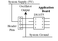
First, the voltage source which feeds the application board's supply must be disconnected. This allows the DS1075K to power up the entire application board. This is only permitted if the total supply current required is less than l00mA. Otherwise, the current rating of the FET which switches the supply on the DS1075K may be exceeded. A typical arrangement is shown in Figure 1.

Figure 1: Application Board Layout
A jumper panel provides a connection to the necessary pins. Two of the pins are used to jumper the board supply to the DS1075 for normal operation (Figure 2).

Figure 2: Connection for normal operation. System supply jumpered to DS1075 pin.
No external connections.
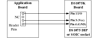
For programming this jumper is removed and a connector is used to provide the necessary connection to the DS1075K (Figure 3).

Figure 3: Connection to DS1075K. Supply and I/O pins of DS1075 connected externally to the DS1075K
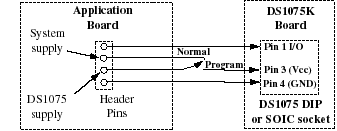
After programming, the original jumper can be restored and the application will work normally. For development work a switch can be added to allow multiple changes without constantly adding or removing jumpers (Figure 4).
For development work, a switch can be added to allow multiple changes without constantly adding or removing jumpers (Figure 4). In production, the header block can be replaced by a wire link to connect the DS1075 supply pin to the system supply (Figure 2).

Figure 4: "Permanent" connection to DS1075K.
Switch selects between normal operation and programming modes.
In production the header block can be replaced by a wire link to connect the DS1075 supply pin to the system supply (Figure 2).