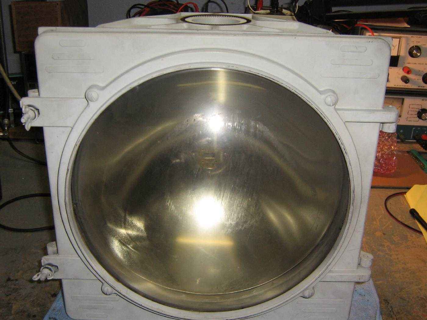
Overview of the General Electric GEMLINK video/data transmitter unit showing the integrated parabolic dish and radome.
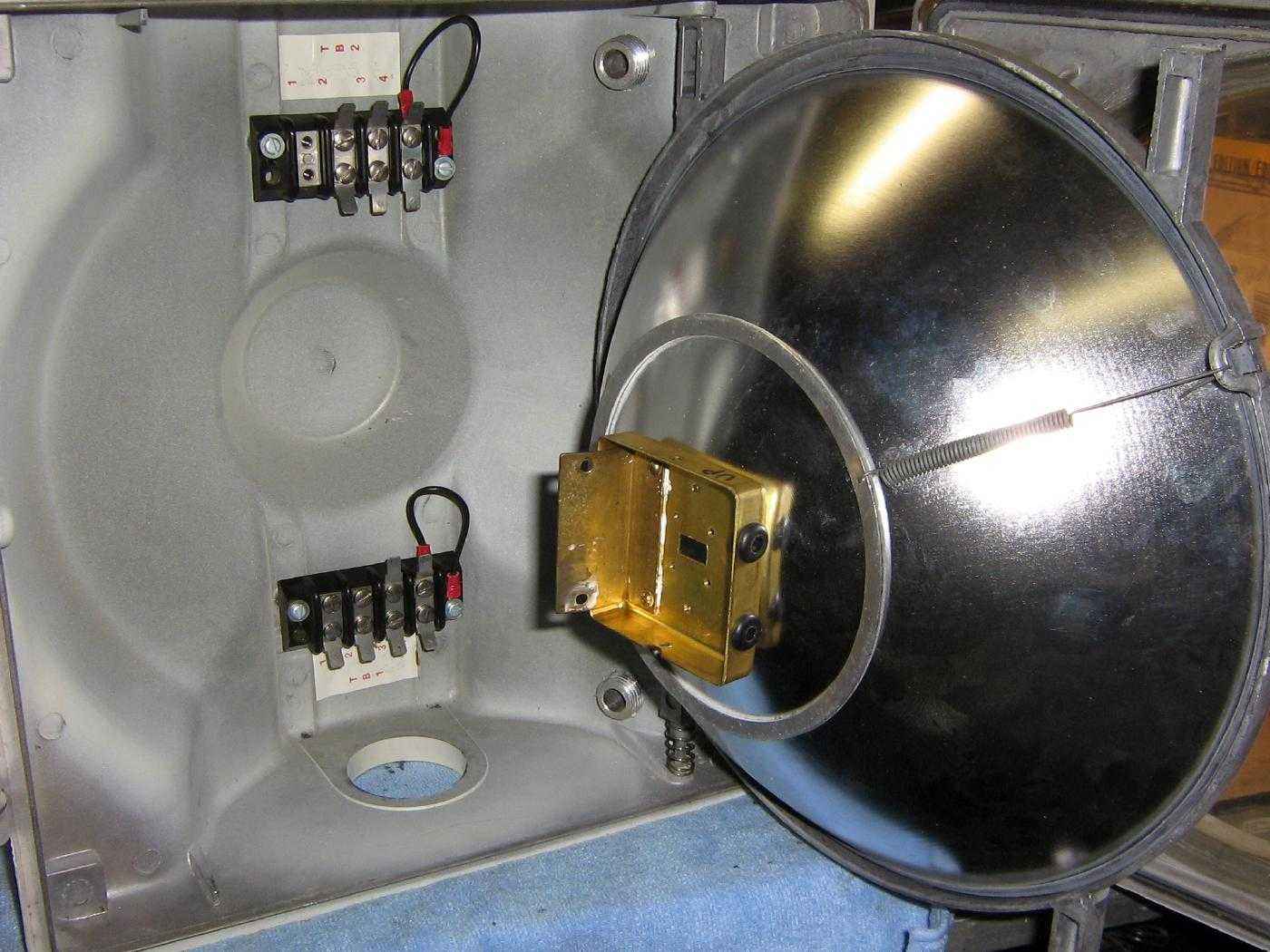
Internal view with the control board/feed asembly removed.
The parabolic dish swings out to easily work on the unit.
Note the spring on the lower-left frame mount point. You can remove the parabolic dish by pressing down on the dish's frame and pulling it out.
The two terminal blocks are where the incoming video/data and power lines are tapped off of.
The top terminal block is labeled "TB2" and the one below it is "TB1".
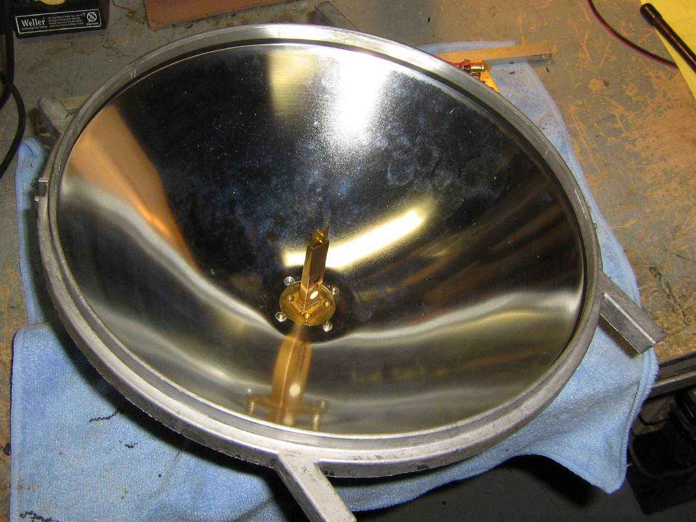
Overview of the parabolic dish showing the location of the feed arm.
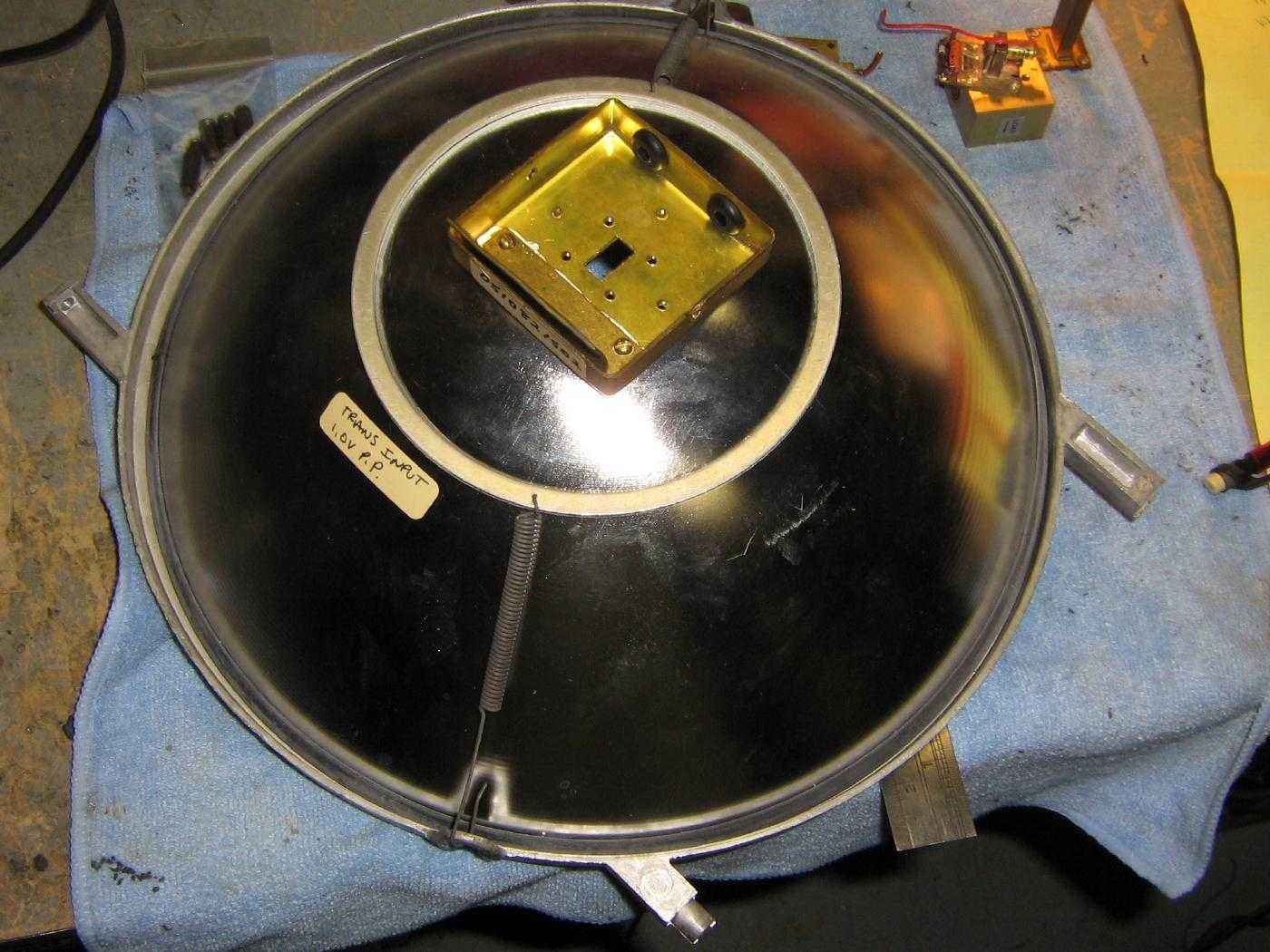
Rear view of the parabolic dish showing where the control board and feed assembly are mounted.
That white label read "TRANS INPUT 1.0V P.P."
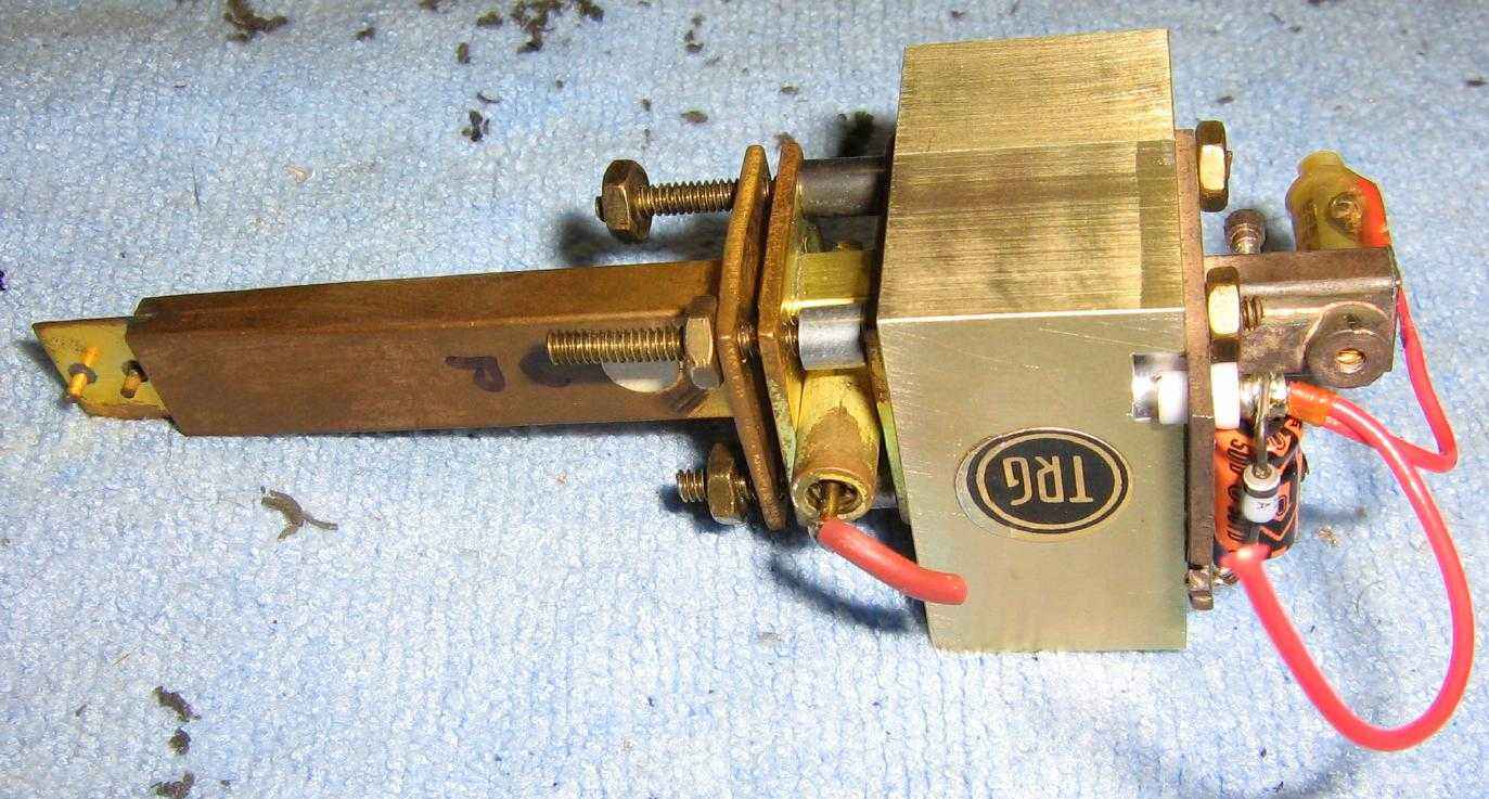
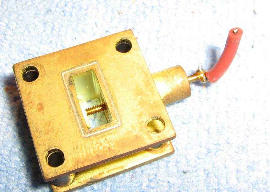
Overview of the feed assembly and the Gunn diode mount.
The Gunn diode mount is on the right. It's powered via the +5.8 VDC output from the control board mounted behind the dish via the smaller red wire.
The large cube-shaped object is the ferrite isolator. This isolates the Gunn diode from any impedance mismatches with the mixer and antenna feed downline.
Between the feed arm and the isolator is a diode mixer with two WR-42 flanges. This mixes the incoming video or data signal (larger red wire) with the 23.125 GHz RF output from the Gunn diode.
This then passes onto the WR-42 integrated feed arm and antenna assembly. The antenna is positioned so it's at the focal point of the parabolic reflector.
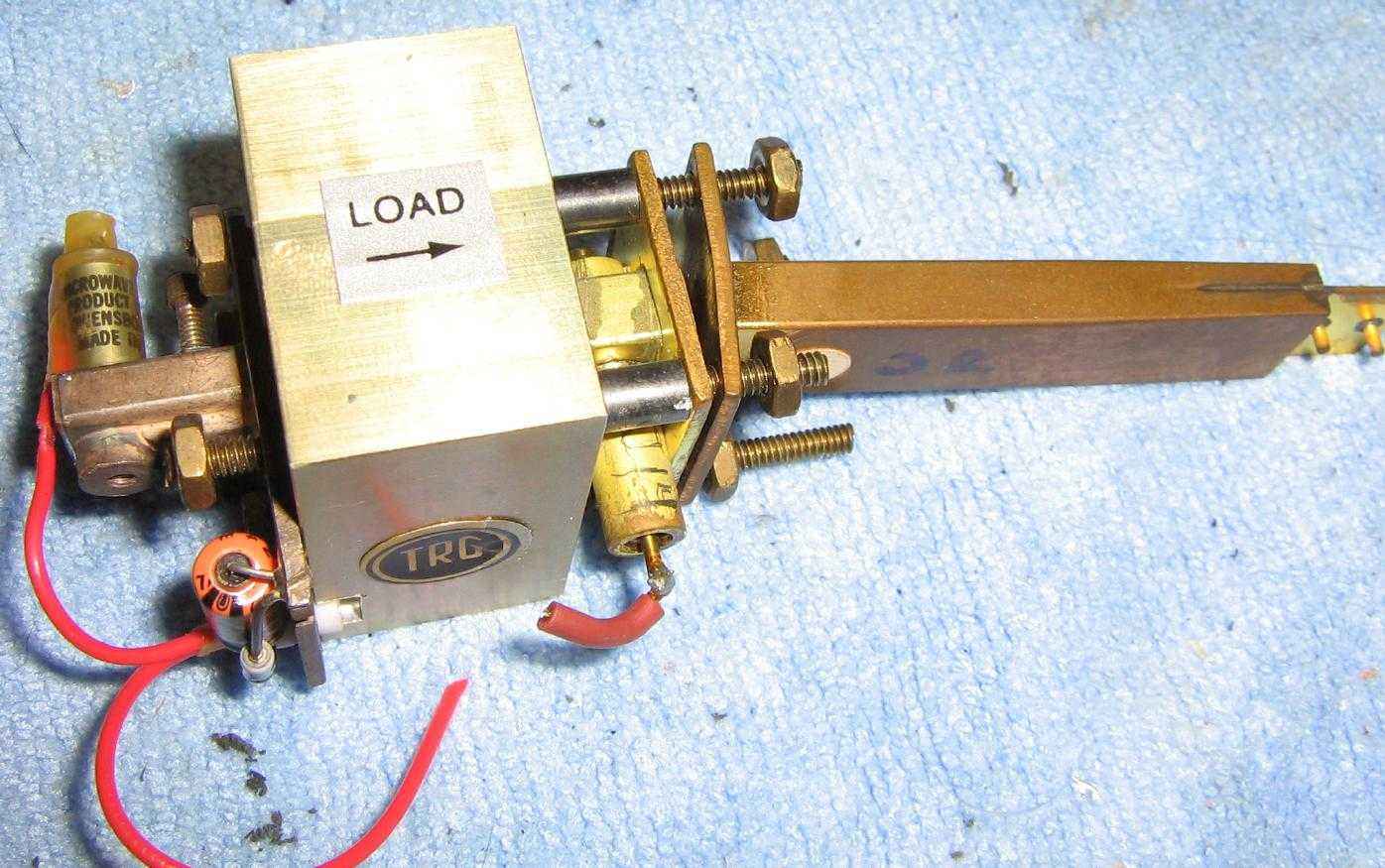
Alternate view.
The entire stack is held together and mounted to the parabolic dish via four #4-40 pieces of brass all-thread and some #4 brass nuts.
The output frequency of the Gunn oscillator can be slightly altered by adjusting the tuning screw in front of the Gunn diode holder.
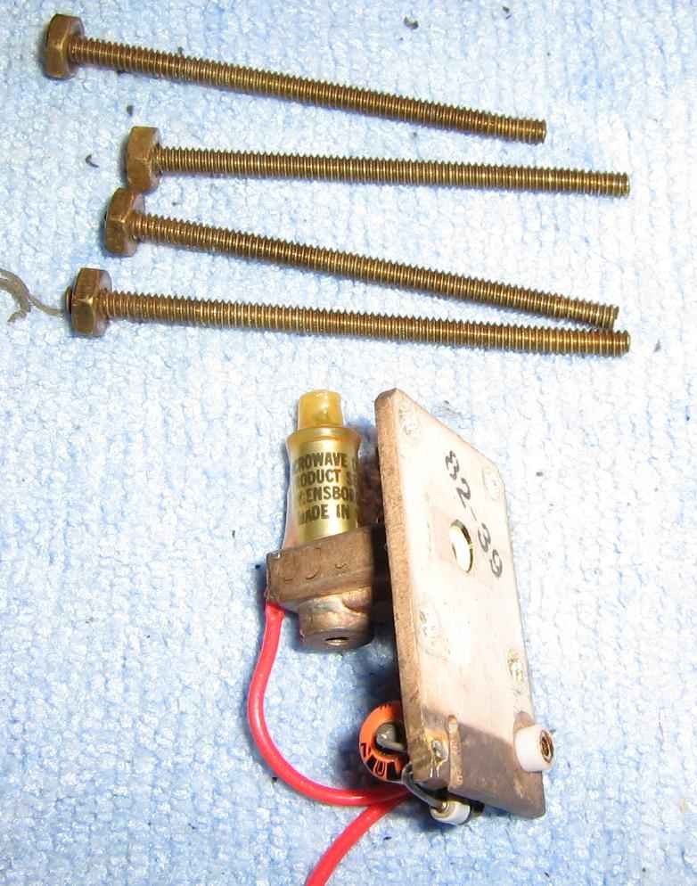
Overview of the Gunn diode mount.
It's labeled C-2138K and is made by General Electric.
It requires a bias voltage of +5.8 VDC.
A 1N4737 Zener diode and 47 µF capacitor help smooth and clamp any voltage spikes on the Gunn diode's bias voltage.
I don't have an accurate way to measure the RF output power (or frequency), but we can assume it's around +7 dBm (5 mW) and 23.125 GHz based on past experience and available FCC data.
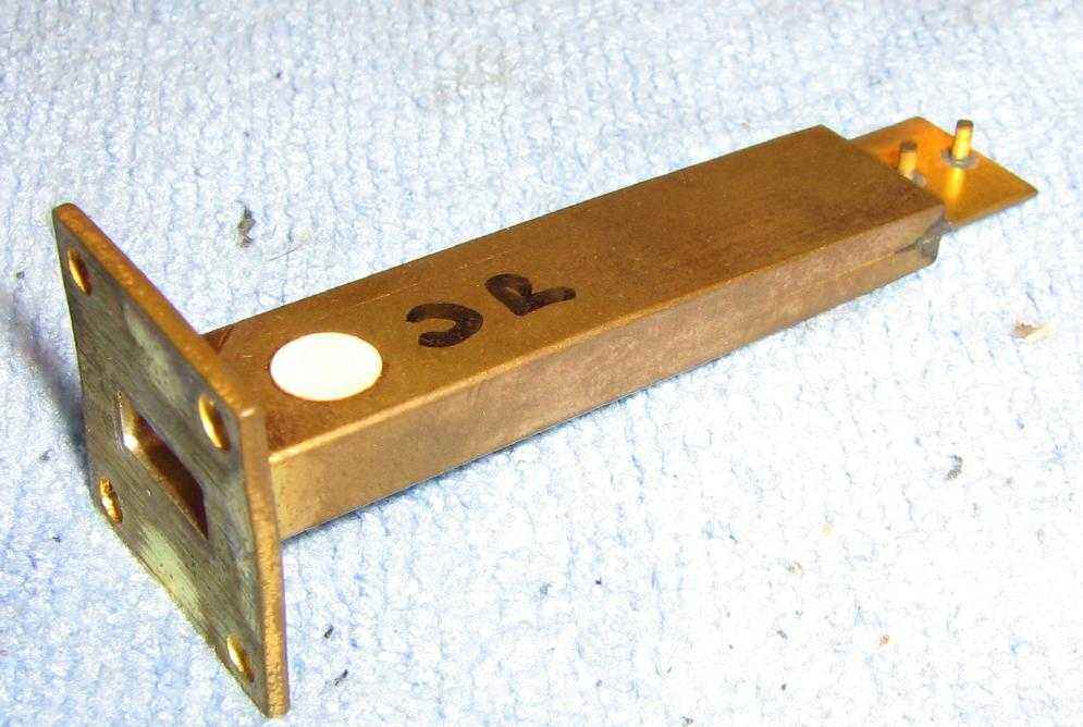
Overview of the K-band feed arm assembly.
This antenna feed is just like the dipole feed and reflector from a Yagi antenna - only much smaller!
Diode mixer mount with WR-42 flanges.
The red wire is the mixer diode feed where the video or data is applied.
There is also a small bias voltage on the mixer diode which is supplied via the control board.
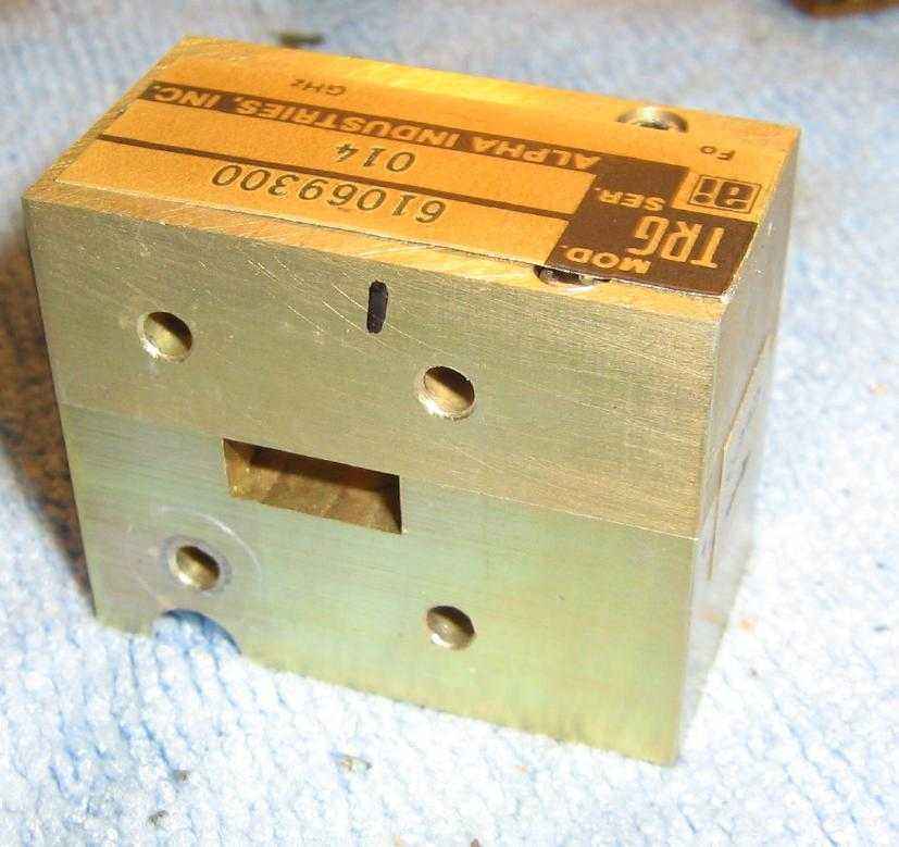
Overview of the WR-42 K-band ferrite isolator.
It's made by Alpha Industries and is model number 61069300.
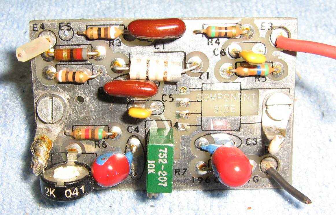
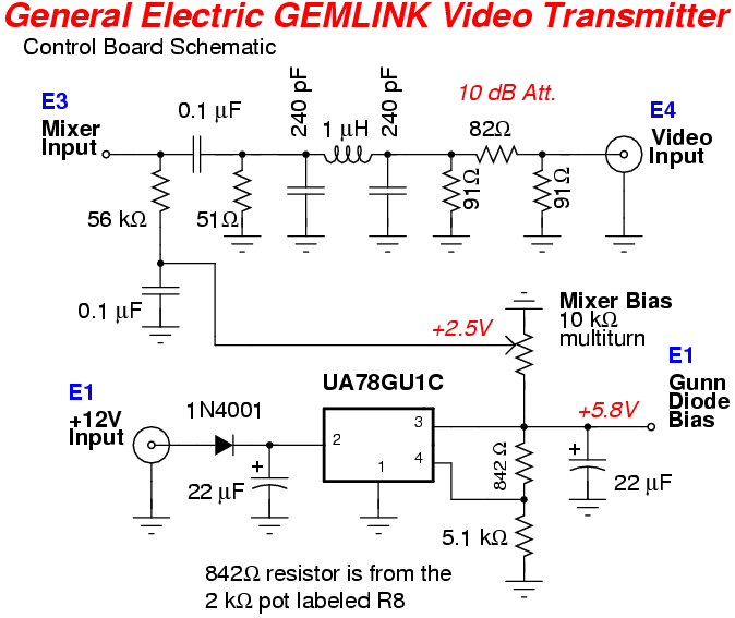
Overview of the control board mounted inside the unit.
It provides a regulated +5.8 VDC bias for the Gunn diode and lower-voltage bias for the mixer diode.
It also attenuates and low-pass filters the incoming video/data signal before applying it to the mixer diode.
The µA78GU1C voltage regulator is mounted on the bottom of the PC board.
The multiturn 10k ohm potentiometer is for fine tuning the mixer diode bias.
The standard 2k ohm potentiometer is for fine tuning the +5.8 VDC Gunn diode bias.
The video/data input, from regular 50 ohm coax, is on the upper-left.
The main +12V input is on the lower-right via the black wire.