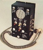
 The 1019 multiple input/output preamplifier/amplifier provides
a near-perfect match to just about any microphone or recorder.
It includes a low noise, high gain preamplifier, 1/2 watt power
amplifier with integral loudspeaker, tone generator, switchable
excitation voltage and a low pass/high pass filter.
The 1019 multiple input/output preamplifier/amplifier provides
a near-perfect match to just about any microphone or recorder.
It includes a low noise, high gain preamplifier, 1/2 watt power
amplifier with integral loudspeaker, tone generator, switchable
excitation voltage and a low pass/high pass filter.
Input jacks, J1 through J4, range in impedance from 2 Megohms to 1,000 ohms. Maximum amplification is through J2 and J3 and medium gain through J4. J1 and its associated (J1) GAIN control has adjustable amplification. With the J1 GAIN control advanced fully clockwise the output level of a signal fed into J1 will be roughly one-half that of the same signal fed into J2.
J1 can sustain approximately 1,000 volts DC. Use this jack when testing line pairs with unknown voltage or signal levels. To operate the 1019, insert the special 2,000 ohm headset supplied into output jack J6 or turn on the power amplifier. The headset is worn with the gray tube under the chin with the sound output holes facing slightly forward. The pre-amp portion (J6) of the 1019 can NOT drive low impedance headphones. Place the MASTER POWER-ON switch in the up position. Turn J1 GAIN fully counterclockwise (minimum) and advance the PRE-AMP GAIN control clockwise (turning ON the preamplifier) roughly one-third turn. Advance the J1 GAIN control slowly clockwise until either a signal is recovered or the control reaches full clockwise. If, while advancing J1 GAIN, a loud hum is heard, it probably indicates the line is carrying high voltage AC. USE CAUTION! Do not apply high-level AC signals to any other input.
J2 (500K) is a high impedance input that uses the maximum pre-amplification of the 1019. Use this jack when the DC and AC level and relative signal strength on a line pair is known.
J3 is used when the line or accessory is near 10K ohms. Accessories such as the 2030A Carrier-Current probe or 1059IR detector connect to this jack.
J4 has lower amplification and impedance (1,000 ohms) than J2 or J3. Use it when an input signal is too high in level for the other jacks. An excitation voltage (9 volts through 4,700 ohms) for external accessories or carbon microphones is available through this jack when the CARBON VOLTS-ON switch is in the up position.
The TONE GEN-ON switch powers an internal tone generator. The tone output is fed through the last three stages of the preamplifier and applied to output jacks J5, J6, J7 and J8.
The FILTER-IN switch selects the amplifier roll-off characteristics. Use this switch when excessive hum is encountered or when a more "crisp" signal is desired.
The output of the preamplifier is fed though the AMP GAIN control to the 1/2 watt power amplifier. Monitor the output of the amplifier through the integral speaker or a set of low impedance headsets plugged into the LO IMP (10 OHM) jack J7. The HI IMP (1K OHM) jack J8 can act as a power driver for any line pair.
To test the battery, insert the mini-plug/clip-lead cable (supplied) into J4, turn ON the 1019 power and place the J4 VOLTS switch in the UP position. Connect the clips to a voltmeter set on the 9 or 12 volt range. The voltage should indicate not less than 8 volts for an Alkaline battery or 7.5 volts for a mercury battery.
To replace the batteries, remove the top and bottom cover screws and, with the unit held face down, carefully lift off the back cover. Remove the old batteries and replace with fresh Alkaline batteries. Replace the cover and screws.
Always turn the unit off by placing the MASTER POWER-ON switch in the down position and rotating the two GAIN controls fully counterclockwise.
| |
11/98