FCC WARNING - This equipment, in some
instances, is capable of exceeding Part 15 of the Rules for
low-power broadcasting. Please be aware that it is possible to
use this equipment in a manner that can place you in violation of
federal laws. Before you construct any of these projects, you
should familiarize yourself with FCC rules with regard to radio
transmission devices, and be aware of the boundry between legal
operation and illegal, unauthorized operation. It is up to you to
assume legal responsibility for your actions as you use this
equipment.
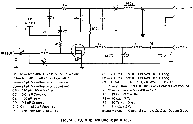
The following section will provide the Motorola schematic for a typical application for the MRF136, a broadband power RF MOSFET that will put out a conservatively-rated 15 watts across the FM broadcast band.

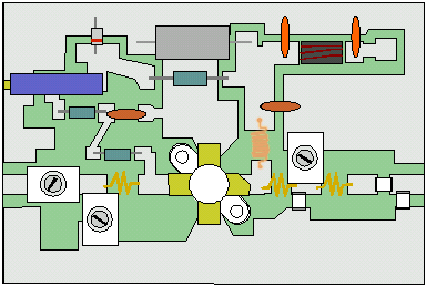
Here are some layouts for the PC boards which I designed based on this circuit. The first layout is a components placement mask and the second one is your photo mask. You may drill holes as needed for certain connections that use components that are not surface mounted.

|
PCB Component Layout for MRF136 |
 |
PCB Photomask for MRF136 |
The flange on the MRF136 may be directly mounted to a heatsink with two 4-40 machine screws, if the heatsink is drilled and tapped. A specially-shaped hole must be cut in the PCB to accept the flange and body of the MRF136 as shown by the thin outline on the photomask.
This amplifier has the notable characteristic of variable gain control via the bias adjustment trim pot. It may be used in conjunction with an SWR bridge circuit to limit power output in the event of high SWR caused by damage to the antenna during a storm, or someone inadvertently disconnecting the coax transmission line. If you wish to implement a failsafe shutdown system that is triggered by loss of PLL lock, I still recommend a power supply cutoff relay for total safety however.