Every microbroadcaster needs to know about their modulation levels -- ACCURATELY. I spent some considerable time researching an inexpensive way to accomplish this task without a $9000 analyzer. The result was a culmination of modifying an existing tuner and adding this circuit to the output.
The meter circuit itself is comprised of two precision rectifiers, fed by a common input. Each rectifier measures one half of the AC waveform coming from the tuner's IF strip. The input features a small compensating network that might be needed for some tuners. The resulting pulsating DC envelope is fed to a peak-hold capacitor, which stretches the duration so that a meter will be able to respond meaningfully to extremely brief transients. One of the two outputs is fed to an inverter, to make the result such that both outputs are positive voltages regardless of polarity of the AC input signal. These two signals are then summed.
The summed signal is sent to the meter ballistics shaper. This circuit boosts the rise time of the meter such that a 50 ms pulse will read over 90% scale, as opposed to barely jogging the needle off zero. The pot allows for calibration of the meter against a reference signal.
 |
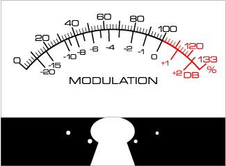
An example of the correct scale markings for the meter. I recommend a 5" scale for accurate readings. The desired meter should be fast-responding, have a large and powerful "motor" magnet and coil assembly so it can respond lightning-fast. A PostScript file of this scale should be made available soon. |
This circuit is not the complete modulation monitor. You need a decent FM tuner, modified so that the baseband IF signal, from the first demodulator is presented to an external jack. Some high end tuners already feature this type of secondary output. Marantz was putting them on tuners back in the 1970s. Sansui had a top of the line model which offered a baseband output, before de-emphasis and stereo decoding circuits. You can modify almost any older tuner to bring this pre-processing signal out to a jack too. You'll need an oscilloscope and some basic knowledge of tuner circuitry. The intent is to locate the first place in the IF strip where the modulation is converted to audio. This will be at a limiter stage or a ratio detector, at the end of the IF strip. It would be helpful to have a stereo exciter and a sinewave generator available to help you locate the correct point in the tuner where main, subcarrer and pilot can all be seen at once. If you send test tone audio through one channel of your stereo transmitter, you should be able to locate a point in the tuner that displays a waveform that looks like the one listed in my section on aligning stereo generators. This patterns shows the subcarrier and mono audio components. This is the correct place to connect the modulation monitor.
Once you've found the unprocessed baseband output of your tuner and have it connected to this meter circuit (with suitable meter connected) you can begin the process of calibration. I used a known 50kW FM station that I had to opportunity to measure on a $25,000 spectrum analyzer/modulation analyzer, so I knew they don't go over 100% and have no SCA or other subcarrier services running. This latter item is important: you must determine if your reference FM station is providing any Subsidiary Communications Authority subcarriers. If so, you need to assume they are modulating an additional 5% over 100% for EACH subcarrier above 53 KHz. It is better to use a high-profile FM station as your reference, and best it be a local one, or one putting better than 4mV/meter into your antenna, for best accuracy in the tuner's audio decoding, as well as the likelihood that a high-power, high-profile station is more likely to follow the rules to the letter, and keep modulation at exactly 100%. Many class A's I've measured modulate at up to 120% on weekends, particularly during a book season. This is illegal, and you should avoid using such stations as a reference for your 100% setting. One way to find out if a station is transmitting SCA subcarriers is to watch their signal on your 'scope connected to your modified tuner. Wait for a natural break in the program offerings and watch the residual signal. If you see a clean sine wave, chances are you're in luck -- this station is transmitting only a pilot tone. On the other hand, if you find something that looks a little like an undulating pattern, like an AM carrer with a tone on it, then there is more than one subcarrier --the pilot and the SCA carrier.
When you are reasonably certain you've found a reliable reference, adjust your modulation meter trim pot so that the needle is frequently hitting 98% and occasionally hits 100%. (Stations with SCA, set this to 105%). If the station's audio is really sloppy, you might find the aperture to be much wider. Wait for denser program material and watch the meter frequently. It should, in most cases, show a definate limit point beyond which it does not go. The tighter the station's audio processing, the easier this threshold will be seen.
Now tune to your station... WHOAH! You see your needle go off the scale if your running a Ramsey kit, right? <g> Now adjust your limiter's output level so that with your loudest program levels the meter does not exceed 100%. (This is where you usually will find that you need to go out and buy a better limiter, since most limiters will have so much slop that the meter will overshoot frequently, and no definate 100% point will be apparent.) Once you are reasonably satisfied with your adjustments, go back and check the reference station. Make sure the levels still hover at 100%. If okay, then chances are, you are pretty well-set with your modulation.