This is a PLL controller that works with the VCO/Modulator that I designed. Use these
two modules together for a complete baseband-capable exciter unit. This PLL controller
features a rock-stable crystal controlled reference, in conjunction with a programmable
dividing network which allows the transmitter to be tuned in 100Khz steps from 79.9Mhz to
109.7Mhz by means of digital thumbwheel switches.
| The photo isolator "gain control" cells are manufactured by the company listed below: |
Clairex Technologies, Inc |
NOTE: These are rough pencil sketches that I used for planning out
the final layout. I never made a photomaster because I used the direct etching process. As
a result, these should not be used as anything other than a routing/layout guide.
Download PCB Layout for Component Side of PLL Controller board
Download PCB Layout for Solder Side of PLL Controller board
Download PCB Layout for VCO board
GIF format 300dpi file of the artwork for printed traces for the VCO. Depending on choice,
you can flip the artwork and use it on the solder side, or on the component side. Either
way will work.
This VCO/Modulator is meant to be driven by the PLL Controller mentioned elsewhere on this page. This is a simple, easily-constructed high-performance carrier generator and modulator, utilizing super-linear properties of a varacter tuning diode to control both frequency and to modulate the carrier in true FM with no AM component resulting. This is the front-end only. I recommend additional amplifiers including the Motorola 2N3553 to boost output power to several watts.
NOTE: Due to the obsolescence of the DS8629 prescaler, I am exploring replacement with California Eastern Laboratories' UPB1506GV or UPB1507GV divide by 64/128/256 prescaler, strapped to divide by 64. This modification will also require a wiring change to the VCO board artwork to accomodate differences in pinouts. In addition, the crystal frequency will change to 3.200Mc, to maintain 100Kc steps on the binary thumbwheel switches.
Recently, another experimenter discovered a source of the DS8629 prescalers at: Bruin
Electronics. Anyone needing the DS8629 should try Jim @ Bruin Electronics; (Illinois) Tel.
(815) 987 2775 Fax. (815) 987 2776.
FINISHED VCO Board view, component side:
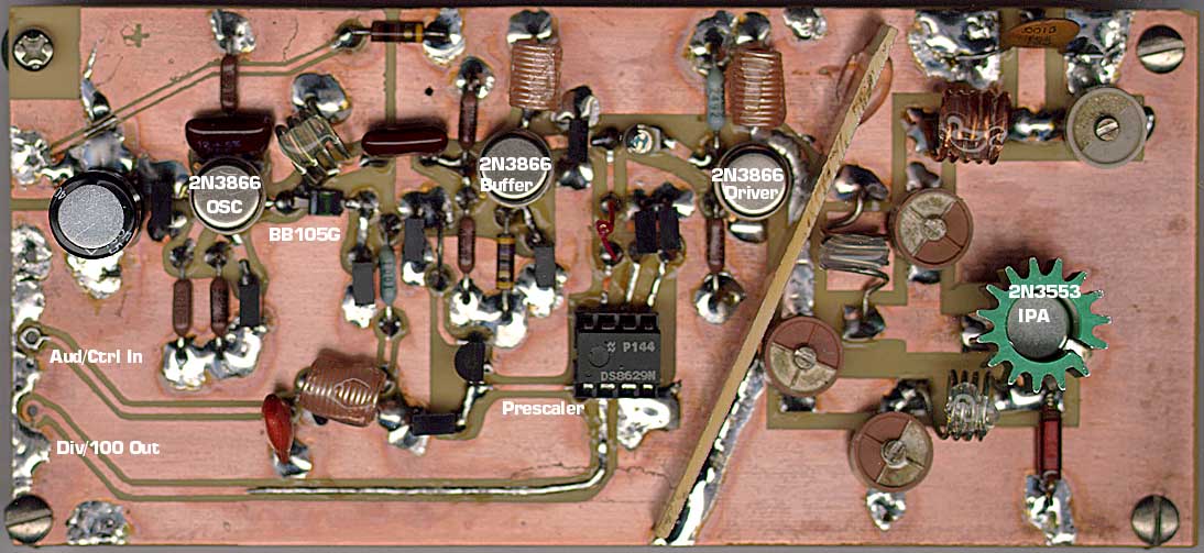
Note use of hand-wound choke coils. Also, it is advised to apply hot melt glue to all coils, to prevent coil loops from mechanically ringing, which would cause microphonics. Keep turns close together on output IPA stage for stability over entire frequency range. Failure to wind these coils properly will result in spurious emissions and unstable operation. Coils are on 3/16" diameter former. Use of a H/P tweaker tool works well to match my results. The 5pF cap that provides RF sample to the DS8629 prescaler is a "gimmick" --a twist of 2 turns #26 Kynar wire, not connected, but cut in the center to form a very small capacitor.
Important detail: Note the "partition" separating the IPA from the rest of the circuit. I used a 5/8" strip of FR4 PC board and soldered it down to the main board on the ground side. Be sure, if you do this, to file away some of the clad from the edge that sits over the "hot" DC power side of the board at the top. The top foil area is +12VDC; the bottom is ground.
I note that my schematic above only contains the first two stages. Sorry for the confusion. I never documented the rest. This photo, which I found recently, should help with placement and coil winding info. The VCO shown here will tune from 84mc to 111mc with a varactor input voltage from +8v to -11v DC. Output level is constant over the range from 87mc to 110mc and no spurious oscillations occur when tuning over the range. VCO is stable into various loads.
 |
The varactor tuning diode characteristics are shown on the chart at left. Note the flat transfer curver over the 1-10 volt range, over which it has a 4:1 capacitance range. That is the range which is used in this design. |
Using all of these components, carefully-constructed and adjusted, you can assemble a
complete FM broadcast system, sans studio, that will sound as good, or better, than
commercial stations, meet or exceed all FCC specs for frequency stability, audio quality,
minumum channel separation, modulation overshoot control, etc. and give you the technical
hardware advantage that no other free radio broadcaster currently finds in the inexpensive
kits sold today. Granted, you will need to produce your own circuit boards for many of
these (though the audio circuits may be build on prototyping breadboard or wire-wrapped)
and need a fair amount of technical know-how to adjust, test and set up the equipment. I
leave these schematics in the public domain for those hearty techical people who wish to
build a better station than what they could get by buying a kit. Use them to further the
goal of free radio broadcasting and the American way!
| CUSTOM CRYSTAL may be obtained from: JAN Crystal Tel: 800-526-9825; Fax: 941-936-3750 |