This document describes actual setup procedures for the optimization of stereo multiplexer performance. Some actual waveforms are shown here to illustrate correct operation.
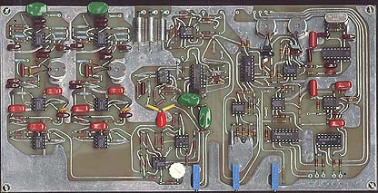
A view of the main PCB of the MUX described on
the schematics page.
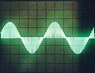
This oscilloscope display shows proper adjustment of subcarrier to main levels. What you're seeing here is a 38Khz suppressed amplitude modulation subcarrier. The signal source is 1Khz audio sinewave, fed to right channel input only. Since no signal is present in the left channel, the flatline exists in between alternate halves of the envelope. The flatter this line, the more precisely the LEFT - RIGHT signal will cancel the LEFT + RIGHT signal. (Note that 19Khz pilot tone was switched off for this photo to simplify the waveform for illustration purposes.)
Stereo generators have a timebase reference crystal which is divided down to two frequencies: 38,000 hertz and 19,000 hertz. These digitally-synthesized frequencies are converted to sine waves by feeding them to a bandpass filter consisting of a resonant L-C network. The tuning of these circuits adjusts the center of the bandpass, which adjusts amplitude and phase. The important relationship between these two carriers is that they are both in phase with eachother. Using a dual-trace 'scope, one should observe both carriers starting from the same point and heading in a positive direction of voltage. Obviously, the 38,000Hz carrier will do this twice as many times per unit of time, but the starting vectors should be in the same direction. Incorrect phasing will result in degraded channel separation, excessive amounts of subcarrier injection needed to offset this imbalance and the legal ramifications involve overmodulation problems. Carrier phase is one of the cornerstones of good stereo transmission.
The 19,000Hz carrier is used as a pilot tone, which, when detected by a stereo receiver, turns on the stereo indicator lamp and associated demodulator circuitry. In receivers, it provides a reference by which the 38,000Hz subcarrier will be regenerated; the receiver simply doubles this pilot signal to 38,000Hz and injects it into the demodulated subcarrier, recovering the AM wave envelope containing L-R or difference channel information.
Another key section of the stereo generator is the matrix. A matrix is a circuit which sends the two channels of audio down two separate paths. The first path is one in which the phase of one channel is inverted by 180 degrees and mixed with the other. This results in no signal output when both channels have the same information being fed through (such as monaural programming), but whose output increases by the amount in which the program information of each channel differs. This is known as the L-R channel. The other path is one in which the two audio channels are added together to form a monaural output. This is fed straight out to the transmitter. Compatibility with monophonic receivers is maintained because a mono program is provided at all times. The L-R signal undergoes more processing however. The matrix must be properly balanced so that left to right separation is as good as right to left separation. In my MUX design, this balance adjustment is on the L-R mixer IC. With both channels fed with identical signal source, this adjustment should be set so that no output results from the L-R op-amp IC.
The balanced modulator is an amplitude modulator whose carrier is the 38,000Hz subcarrier signal mentioned earlier. The modulator is a supressed carrier modulator, that is that the carrier itself never appears at the output -- only the modulation sidebands do. This little "transmitter within a transmitter" is modulated by the L-R signal. In effect, the suppressed carrier modulation that results is an AM signal without the carrier, which contains the difference between left and right audio channels. As you can guess, this signal only is substantial when program content with diverse left and right sounds is being transmitted. This output is combined in precise balance of levels with the monaural L+R signal from the other section of the matrix. The pilot signal is also mixed in, at about 8-10% modulation, along with the main (L+R) and subchannel (L-R) signals to form the composite baseband signal. The Balanced Modulator in my MUX requires no user adjustments, because the exclusive DC coupling circuit is self-balancing, garanteeing maximum carrier suppression at all times.
In the monaural receiver, the L+R signal is simply passed on straight to the speakers, however the stereo receiver feeds this signal into a matrix circuit and decodes the L-R signal from the suppressed carrier AM signal that is received on the FM carrier as part of the composite baseband. Since there's no carrier, the receiver must regenerate it. The 19,000Hz pilot tone serves in two ways: to act as a signal to tell the receiver to switch to stereo decoding mode and to use this signal as a phase locked reference to generate the carrier to add back to the suppressed carrier AM containing L-R information. The receiver does this by doubling the frequency of the pilot tone and deriving a 38,000Hz carrier which it mixes with the L-R subcarrier. This signal now becomes true AM, from which undistorted audio containing the differnce between left & right channels can be derived. The resulting signal is also fed to the matrix.
Let's look at how this recovery of channel separation for stereo is accomplished. For simplicity, we'll assume one channel is modulated and the other is silent. The L+R matrix will be putting out a signal and the L-R matrix will be putting out a signal, because the difference between channels is 100%. A waveform similar to the scope photo above is the result. Alternating halves of the waveform are missing, or flat because the L+R is effectively cancelling out those vectors.
The receiver accepts these signals, decoding the L+R, and the L-R and feeding them to the matrix. The monaural signal would appear in both channels, except that the difference signal decoded from the L-R subcarrier recovered audio is 180 degrees out of phase with the mono audio in one leg of the matrix, effectively cancelling the signal in that half of the matrix. So one channel has the signal and the other does not. But that's what we put in the transmitter, so effectively, we have stereo transmission.
Ultimately, when setting up a stereo generator, some verification of results are necessary. Using several receivers and comparing channel separation optimums by adjusting the subcarrier injection, you can get a good idea of the best setting which yields the best separation on most of the receivers. Of course, your subcarrier should look as close to flat as possible when a sinewave tone is used as a test signal (see photo above). Be aware that if you are unable to obtain 50 or better decibels of channel separation, you may have a problem with your transmitter's modulation characteristics. Stereo requires phenomenal transmitter audio performance. See Tech Note BC-02 regarding bandwidth requirements for optimum audio performance.
Presented to you by
The "Peg-legged" Bass Pig
Please make every effort to be a responsible broadcaster. The more knowledge you have, the better your capabilities to reach this standard and very important goal.
Authored by your friendly "Peg-legged" Bass Pig