The 1059IR is powered by either J4 or J3 of the 1059. The unit contains a Wratten IR filter that blocks virtually all visible light.
Insert the plug into jack J4 on the amplifier. Place the J4 Volts On (red) switch in the UP position to supply power to the probe. Insert the 2,000 ohm headset into J6 and adjust the 1059 for normal operation.
At a distance of 3 feet the probe "sees" an area roughly 1 foot in diameter. Any fluorescent lamp (since they emit much more IR than an incandescent bulb) in the area should be turned off by removing the bulbs. Point the probe in the desired direction and slowly scan the area with one foot overlapping sweeps. Pay particular attention to the level of background noise heard through the headset. If the ambient light level in the search area is too high or an IR transmitter operating at frequencies above the normal hearing range is detected, the amplifier will fall silent. If possible, lower the ambient light level or shade the search area. Make sure that a slight background noise is always heard. The unit may be tested with a TV remote control. Point both the control and 1059IR at any shiny object to hear the controller signal.
If, for reasons decided by the user, more amplification is needed remove the bottom cover of the 1059. Note that an orange wire connects J4 to the Tone - On (blue) switch. Disconnect this wire at the J4 end and connect it to the same jack terminal on J3. This will make the J4 Volts On switch a J3 Volts On switch. Bear in mind that this increase gain may cause the 1059 to saturate more easily.
Again... Always pay attention to the background noise to determine if the system is saturated.
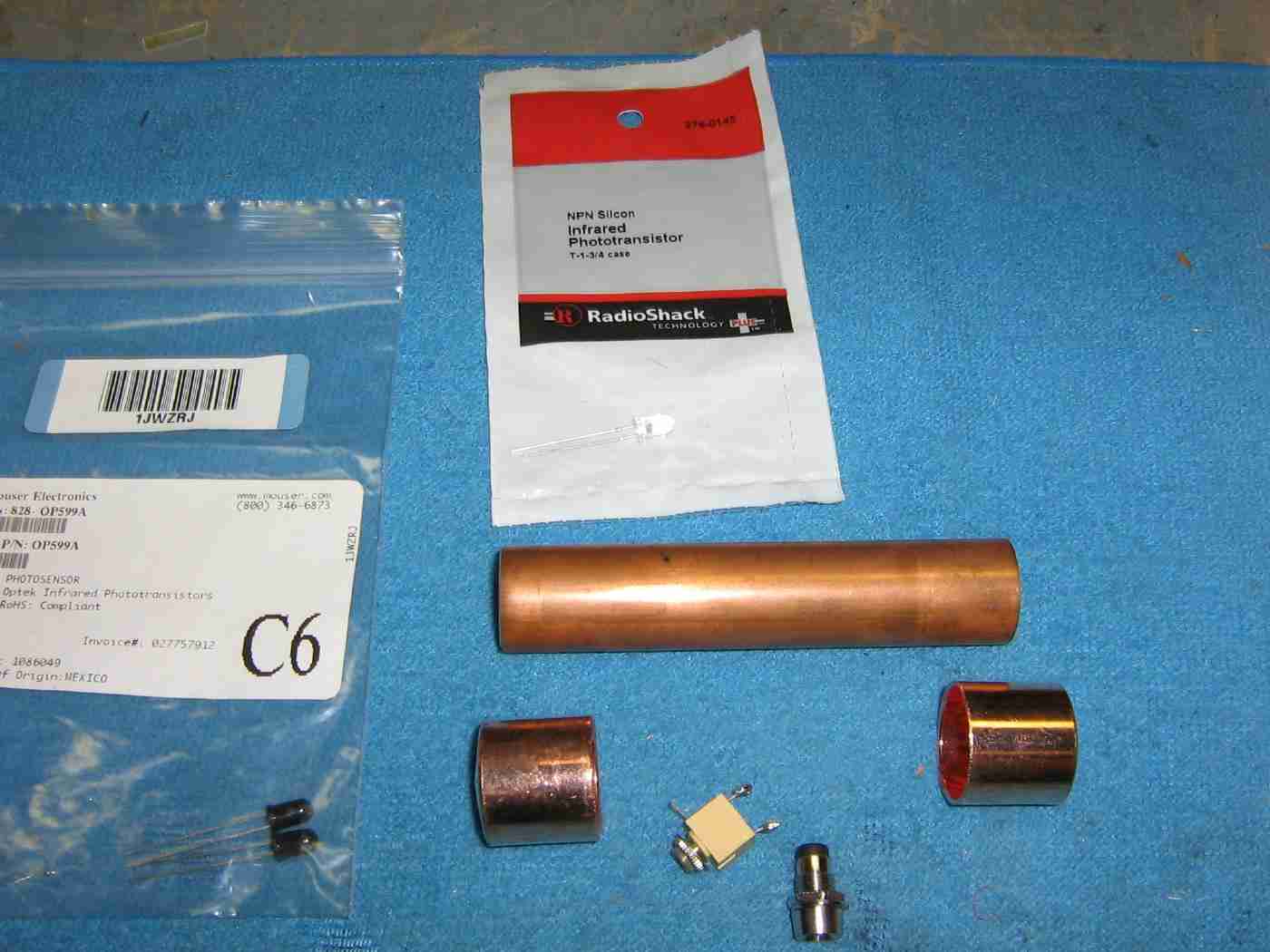
Parts overview.
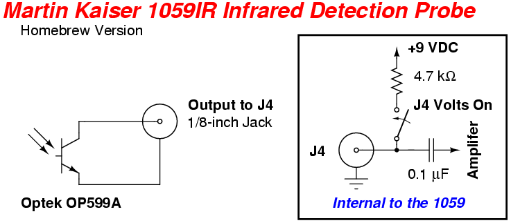
The Optek OP599A phototransistor was used because of the fact that it contains an internal infrared bandpass filter molded into the lens of the phototransistor. This filter highly rejects the phototransistor's response below the 700 nanometer (visible) wavelength.
It's also possible to use a normal Radio Shack 276-145 phototransistor (or an equivalent) if you need a wider frequency response.
For a little bit of extra gain, it's possible to arrange the Optek OP599A phototransistor in a Darlington configuration, but you may find that the lower gain is more helpful, as this prevents the overall circuit from saturating.
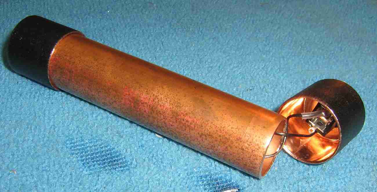
Cut a piece of 3/4-inch diameter copper pipe about four inches long. This will act as a handle. You may prefer to make it a little longer (or smaller).
Drill a hole in one of the 3/4-inch copper pipe end caps to fit the LED holder.
Drill a hole in the other 3/4-inch copper pipe end cap to fit the 1/8-inch jack.
Mount the Optek OP599A phototransistor in the LED holder.
The "flat" side of the Optek OP599A is the collector. This should go to the "tip" of the 1/8-inch jack. The emitter of the Optek OP599A should go to the "sleeve" of the 1/8-inch jack.
Secure the end caps to the copper pipe handle using JACO Just-For-Copper solderless copper bonding adhesive.
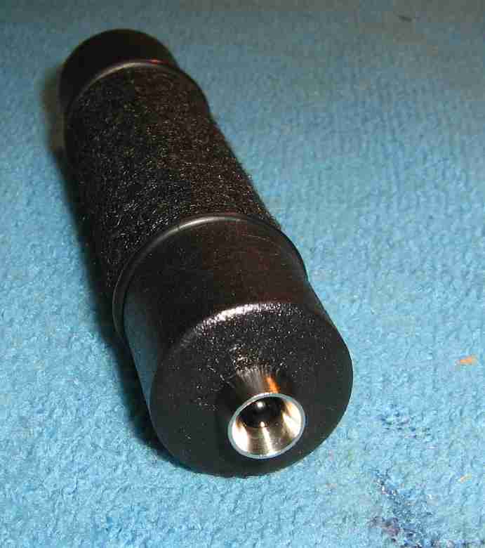
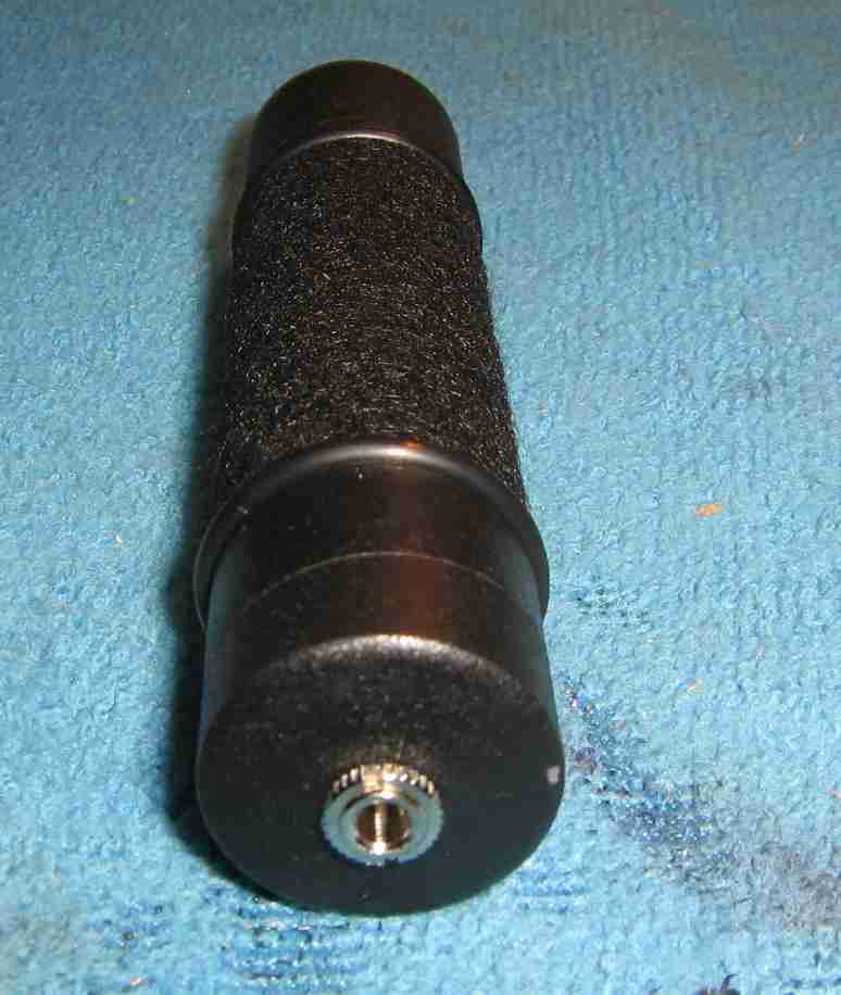
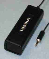
Completed 1059IR Infrared Detection Probe.
The copper was spray painted flat black and a piece of sticky-backed felt was wrapped around the handle section.
Two large O-rings were also added around the handle to act as shock absorbers and to prevent any scratching.
Use the infrared detection probe and the matching 1059 amplifier by "listening" to the level of the background noise.
There should be constant static if no infrared signal is being detected.
When a strong infrared signal is detected, the noise will suddenly go "full quieting." You can test this method by pointing the probe at an incandescent light operating at 120 VAC.
Lights in the distance will have a 60/50 Hz hum, while a strong light nearby will appear to be "quiet." This is because the phototransistor is saturated by the strong light.
When the phototransistor isn't saturated by too strong of a signal, you'll be able hear any carrier modulation(s), if they happen to fall within the normal hearing frequency range. Use an oscilloscope on the J5 output to view any out-of-band signals.