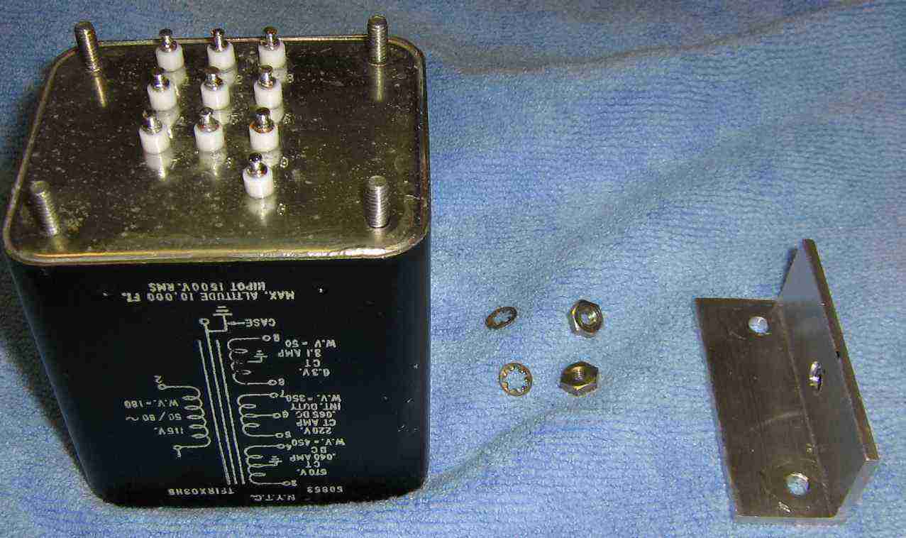
Isolation transformer which will be used for the dedicated AC outlet for the oscilloscope. It is from an old Korean War-era teletype machine. High-quality, sealed voltage transformers often show up at swap fests for only pennies, or even for free. The transformer will be mounted to the side of the case with a little aluminum bracket.
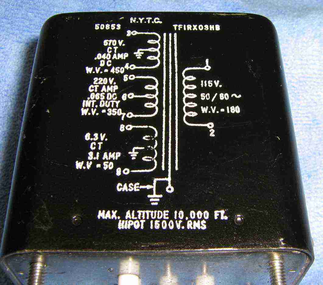
Close up picture of the transformer's label. We'll be using it as an isolation transformer. Standard 120 VAC input is on the right (pins 1 & 2), while the 240 VAC output is via pins 5 & 7. Note that the output winding has a 120 VAC center tap (pin 6). If your oscilloscope doesn't draw too much current you can use this instead. If your oscilloscope does draw alot of current (more than 0.5 A), adjust its internal power supply to accept 240 VAC input and use the 240 VAC output winding.
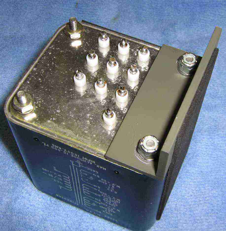
The aluminum L-bracket is attached to the transformer as shown. The back of the transformer has a piece of art foam for protection.
The output of the isolation transformer is sent to a single-ganged outlet. It is mounted inside a metal box and is connected to the case via two 1/2-inch L-brackets.
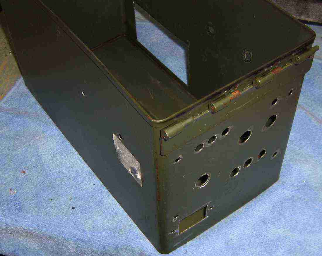
Ammo case used to house this project. The long, retangle cut is for the oscilloscope outlet box. The rest of the holes on the front panel are for switches, LEDs, neon lights, circuit breakers, etc.
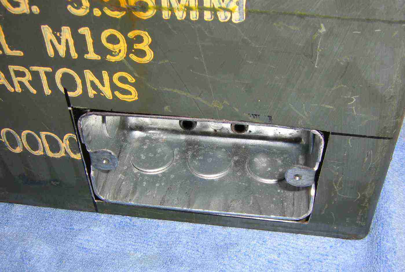
The isolation outlet mounts like this. Cut the retangle hole using a Dremel tool with a cut-off wheel. Be sure there is room for the cover.
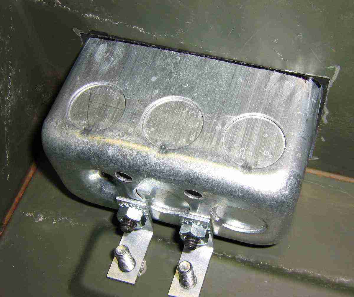
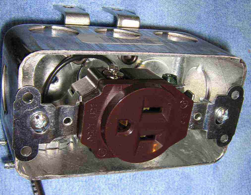
Internal view of the isolation outlet box.
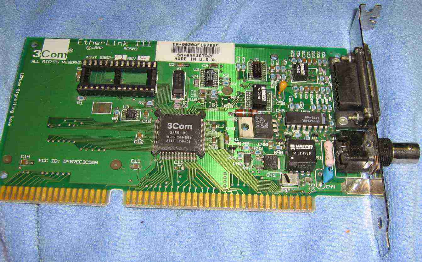
The signal output to the oscilloscope needs to be isolated from the case. A good way to do this is to salvage an isolated BNC connector from an old 10base2 (coaxial) Ethernet card. A 3Com EtherLink III is shown above.
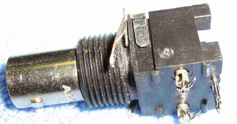
Close up picture of the isolated BNC connector. The two pins on the rear are for the BNC's center pin and shell.
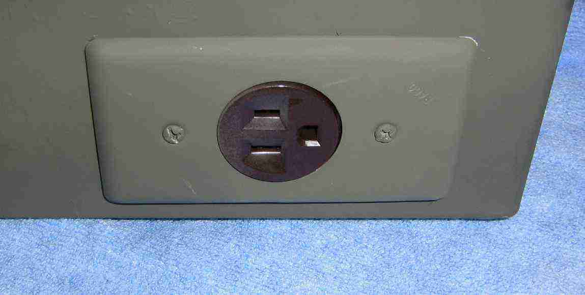
Isolated 240 VAC outlet for the oscilloscope.
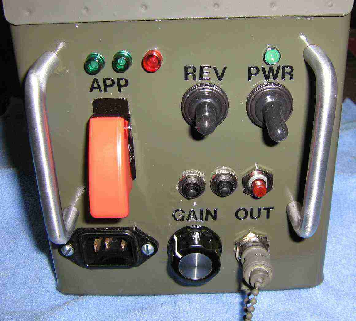
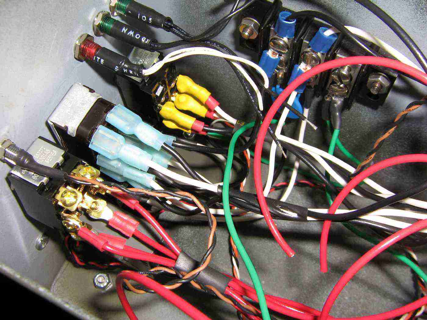
Front panel overview. On the top left are three neon lamps. If the "hot" and "neutral" lines are reversed, the RED neon lamp will light. If the hot, neutral, and ground lines are applied correctly, the two GREEN neon lamps will light. To the lower-right of the neon lamps are two switches. The one on the far-right controls the main power (PWR) to the Carrier-Current Detector and lights the LED above it. The one to the left, (REV) reverses the "hot" and "neutral" lines, in case they happen to be applied incorrectly. Below the neon lamps, with the red switch cover, is the APP switch, which is the final control switch that applies the power line to the main detector circuitry. To the right of that, are three 1 Amp circuit breakers. Two are in series with the "hot" and "neutral" lines, and one is for the isolated 240 VAC outlet. Below that, is the isolated BNC output (OUT) connector and the detector's manual gain (GAIN) control. The AC power line to be checked comes in via the socket on the lower-left. This is also tapped by the isolation transformer to power the oscilloscope.
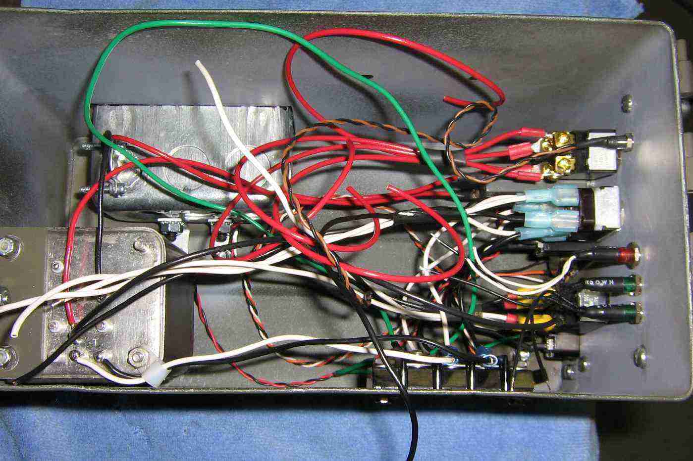
Oh Lordy! The start of the wiring behind the front panel. It'll be a mess.
Close up, alternate view. The 120 VAC input (top) is on a little connector board.
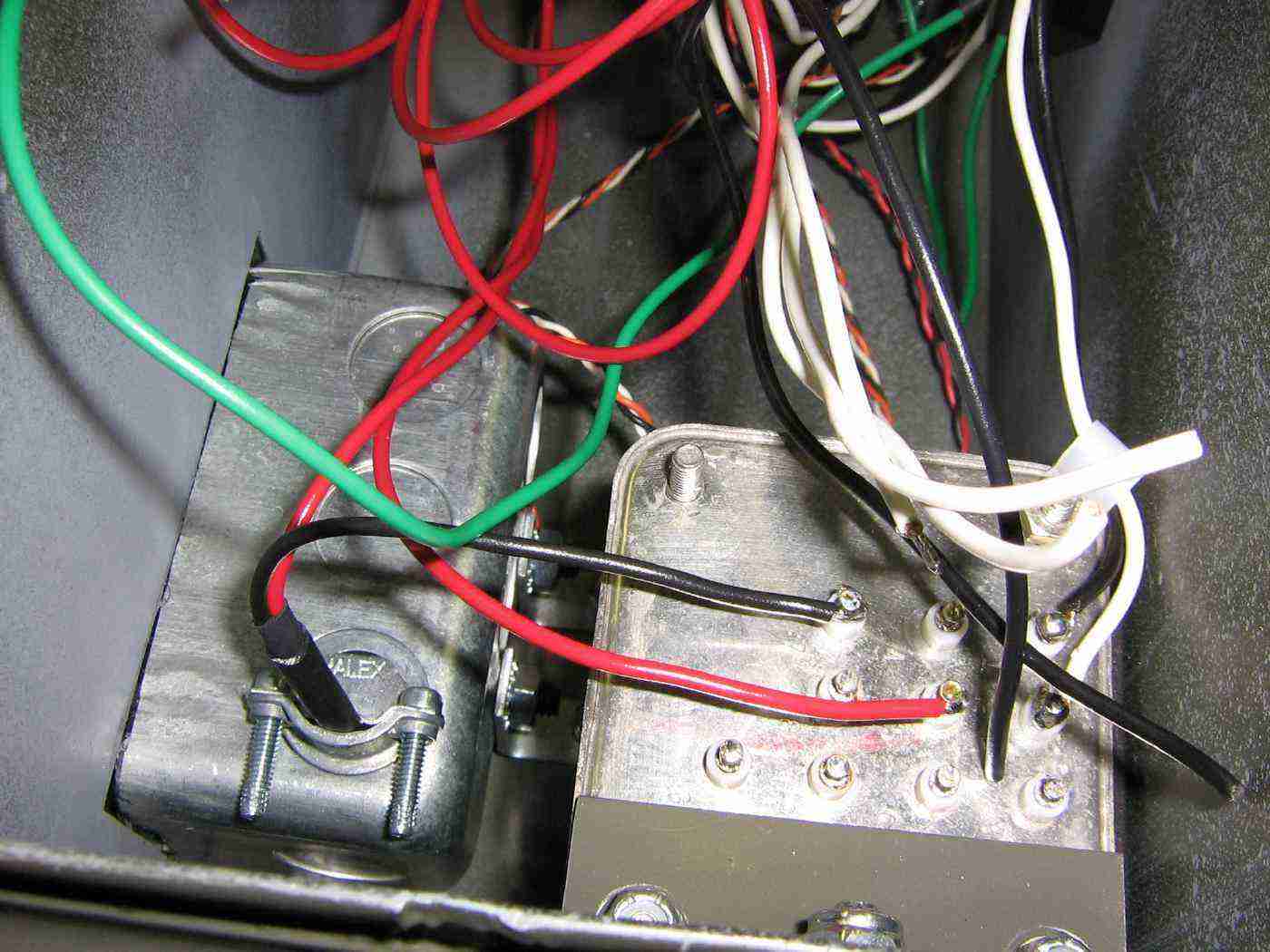
Wiring connections for the isolation transformer and the AC outlet.
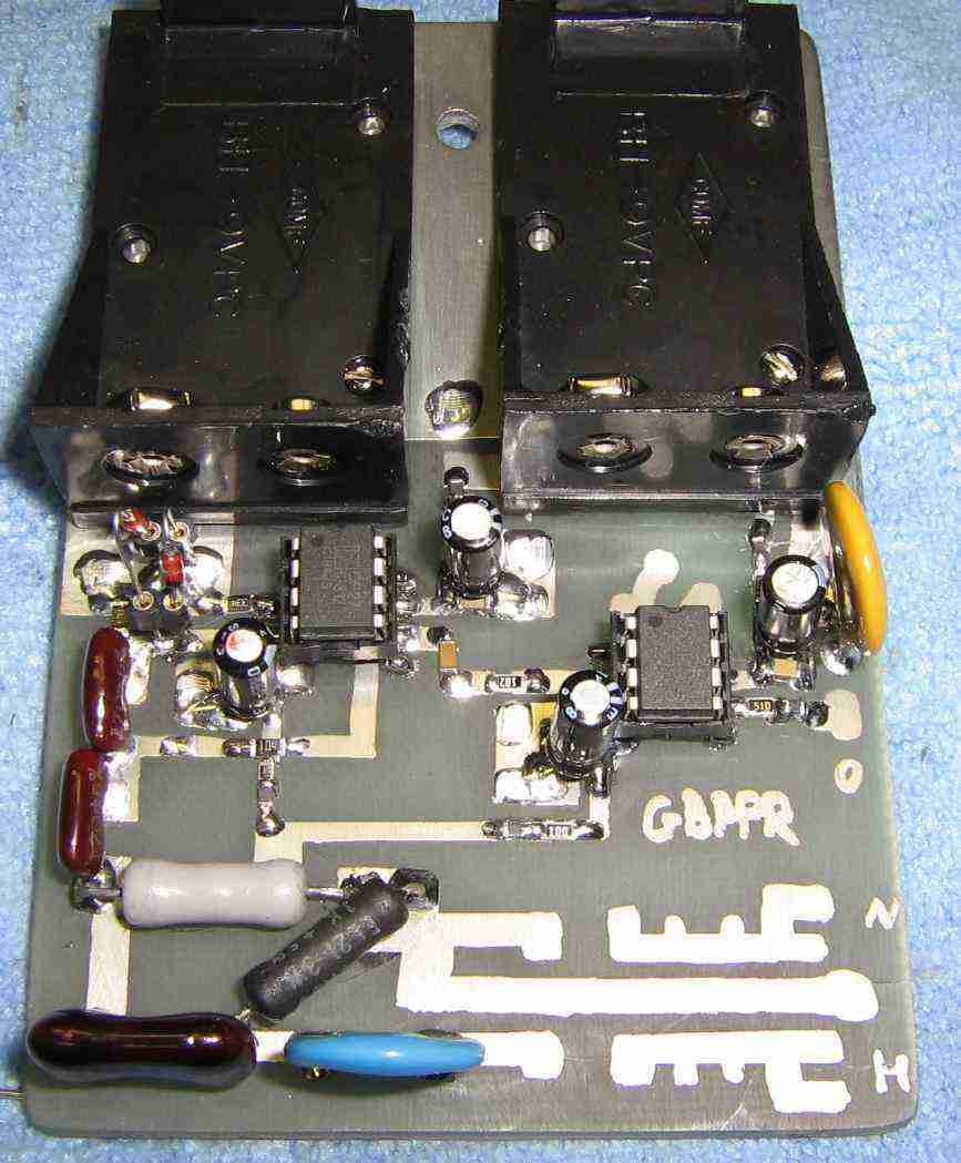
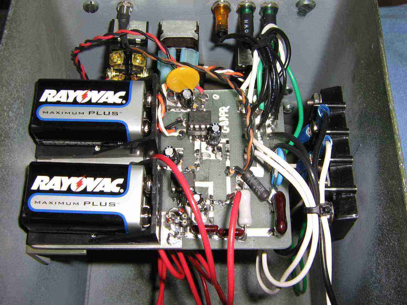
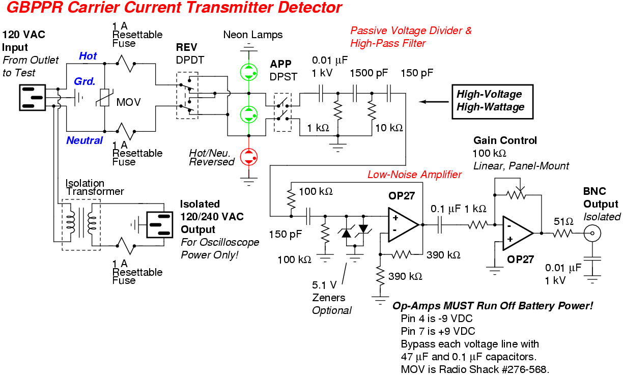
The main carrier-current detector board. It consists of a simple resistor/capacitor voltage divider, and low-pass filter feeding two OP27 low-noise operational amplifiers. Two back-to-back 5.1 V zener diodes protect the incoming op-amps. The detector circuit needs to be powered via two 9 volt batteries to generate the "plus" and "minus" power supplies.
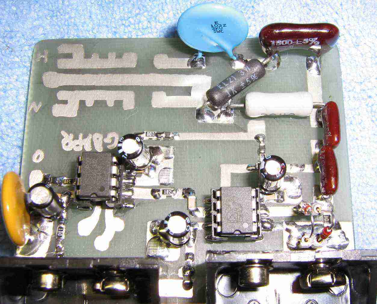
Alternate view. The resistors and capacitors in the voltage divider / filter section should be of the high-voltage type. Silver mica or 1000V ceramic capacitors are recommended. Metal oxide resistors should also be used.
Zoomed out a little bit.
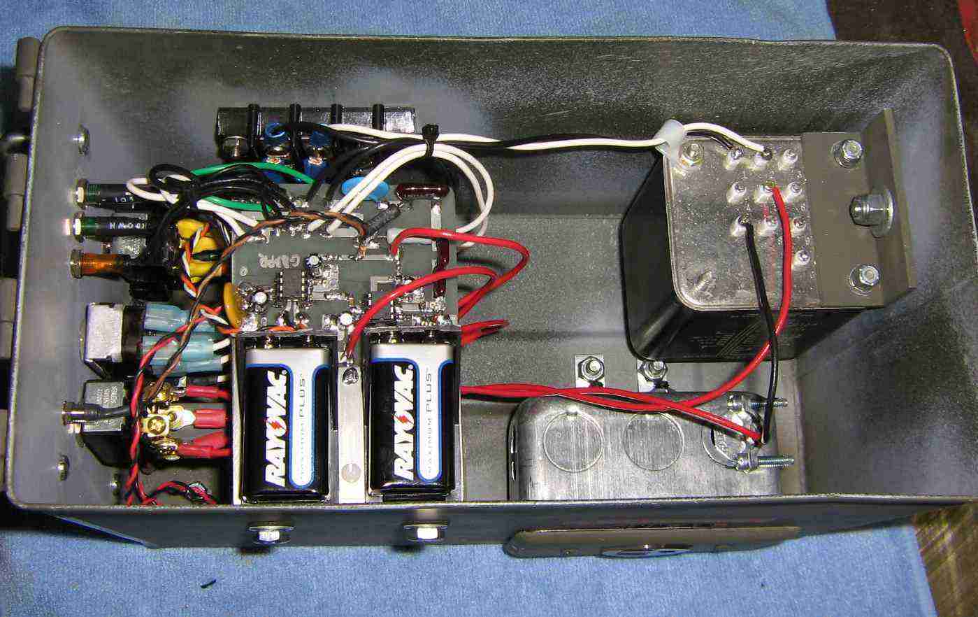
Overall view with the detector board mounted inside the case with the wiring complete.
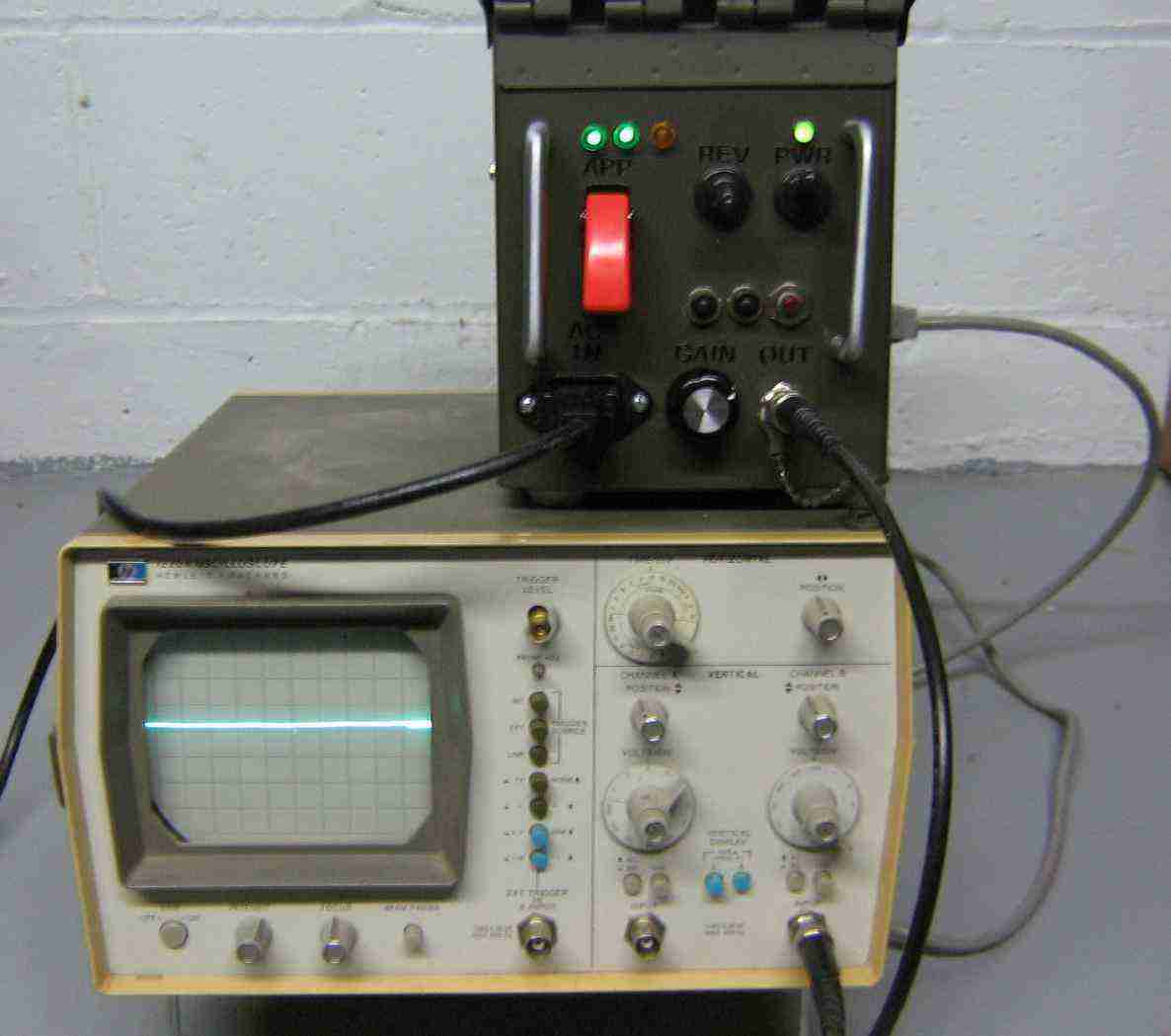
In operation. Connected to a 120 VAC power line, but with the APP switch in the "off" position.
Note the oscilloscope's power cord connected to the isolated 240 VAC output (right side).
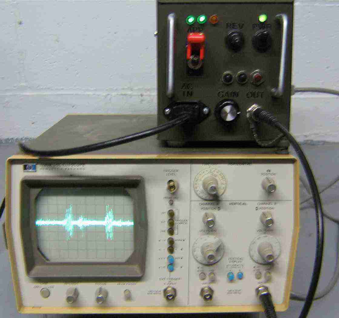
In operation, with the APP switch now "on." The oscilloscope's time-base setting is 1 mS per division. The volts settings is 500 mV per division.
The oscilloscope's display shows noise and switching transients on the power line I was checking. You'll need to compare these signals as a before-and-after picture against a "clean" line if you wish to determine if a carrier-current transmitter is on the line.
Also note that this "noise" is what degrades the use of carrier-current surveillance transmitters.
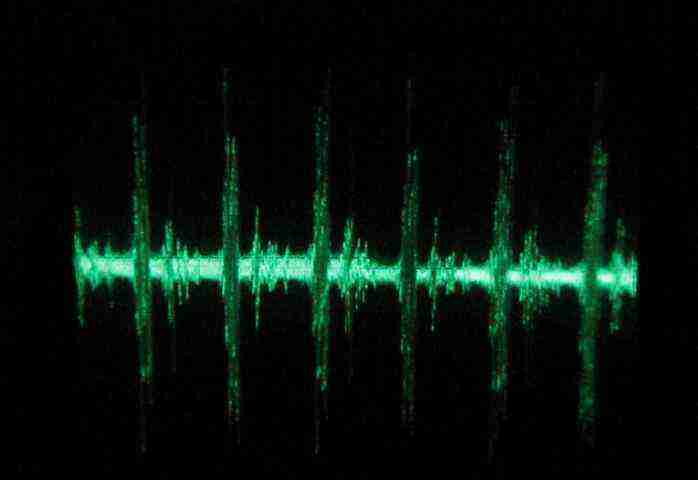
Close up photo. 2 mS per division time-base setting.
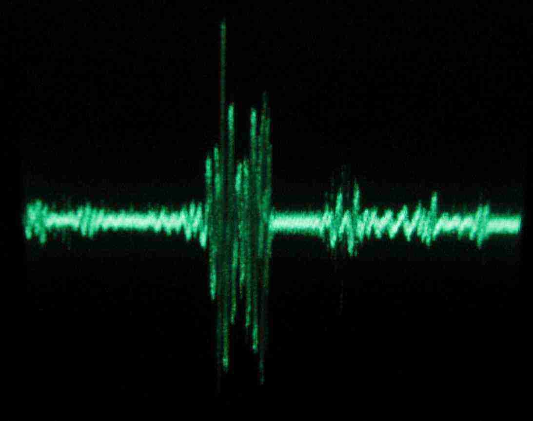
Close up photo. 0.5 mS per division time-base setting.