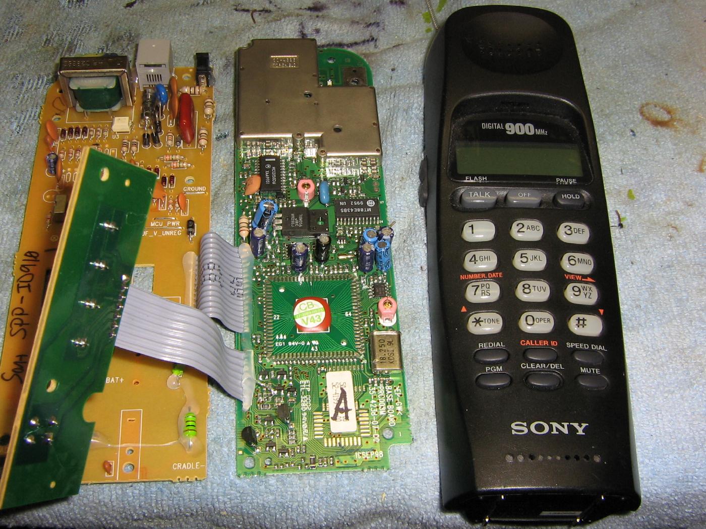
Internal overview of a stock Sony SPP-ID910 900 MHz digital cordless phone.
The phone's FCC ID is: AK8SPP-ID910
The active handset and base station center frequencies are:
Display Channel       Handset (MHz)   Base (MHz)

0                     925.05          902.3
1                     925.35          902.6
2                     925.65          902.9
3                     925.95          903.2
4                     926.25          903.5
5                     926.55          903.8
6                     926.85          904.1
7                     927.15          904.4
8                     927.45          904.7
9                     927.75          905.0
The handset transmits 22.75 MHz higher in frequency than the base station and a new channel in assigned whenever the unit is powered.
It is usually easier to intercept the cordless phone's base station signal as these are stationary and the RF signal won't contain any additional signal losses caused by antenna polarization mismatches from movement.
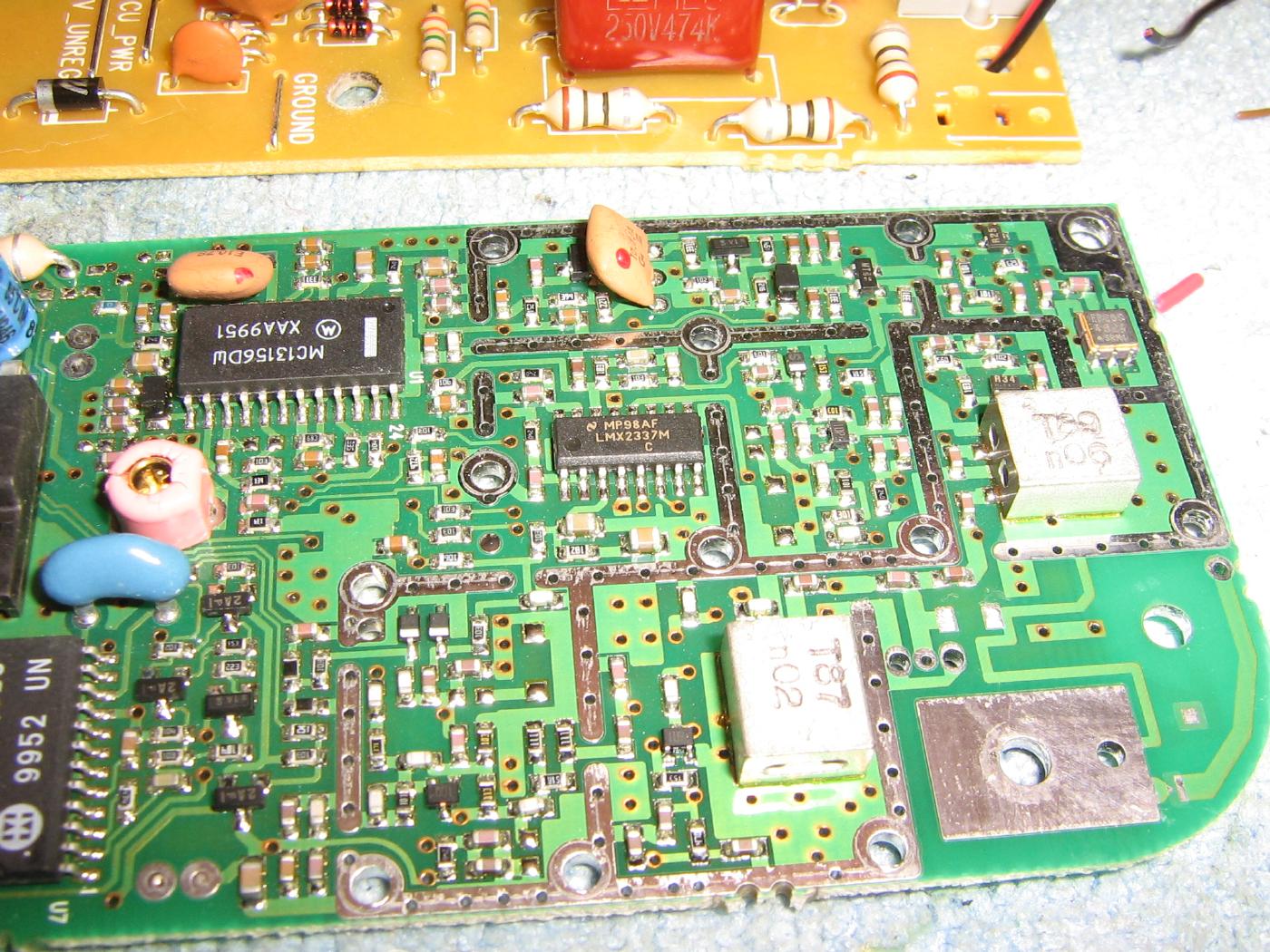
Overview of the RF section of the Sony SPP-ID910.
The antenna input on the lower-right and the two silver squares are the bandpass filters for separating the high/low transmit/receive frequencies.
A National LMX2337 dual-PLL synthesizer controls both the transmit and receive local oscillators.
The 10.7 MHz IF strip is based around the Motorola MC13156 (large IC on upper-left) which is specifically designed for receving narrowband FSK data transmissions.
The data stream output from the Motorola MC13156 (pin 17) is then sent to the AMD AM79C490 for audio decoding and the final coupling to the phone line.
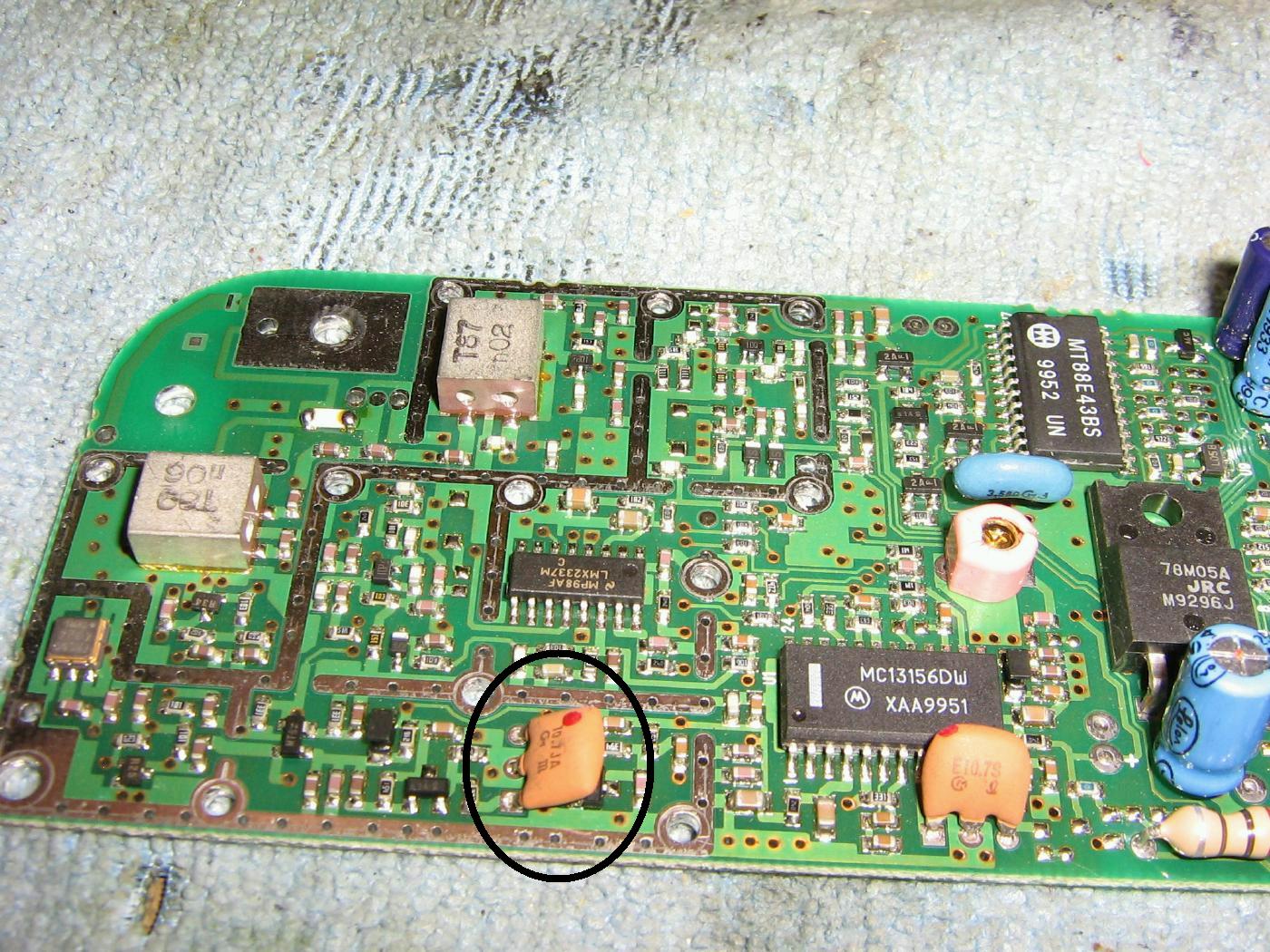
The circled 10.7 MHz IF filter will need to be unsoldered.
The solder pads will then be used to handle the new incoming IF signals.
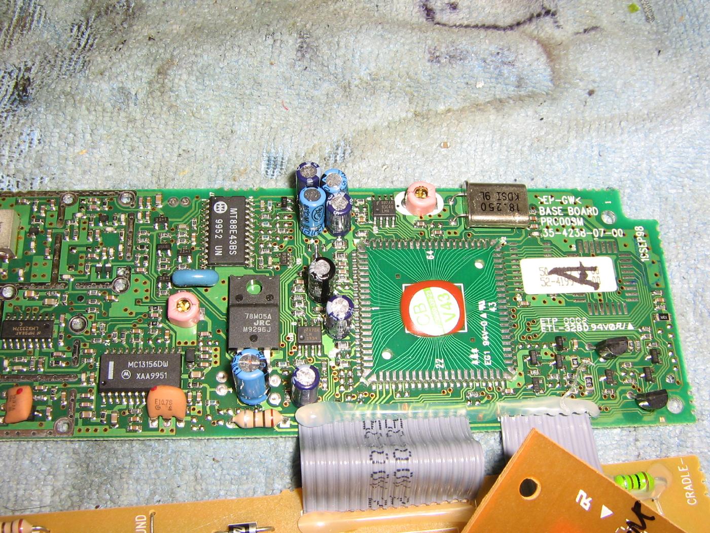
Overview of the 84-pin AMD AM79C490 telephone controller IC.
Details on this IC are difficult to track down, but here's a description of some of the main pins:
Pin No.   Label   Connection Within the Phone

1         AOP     Audio Output
2         AOM
3         AIM     Audio Input/Microphone
4         AVss1   Ground
7         AVcc1   +5 VDC
8         TST1
9         MODE0
10        MODE1
84        AVss2   Ground
83        BATMON
82        AVcc2   +5 VDC
81        /RESET
80        TST0
79        MON3
78        MON2
77        MON1
76        MON0
75        RXBB    Receive Data from MC13156
74        TXBB    Transmit Data to VCO
Note that there appears to be two pins labeled for "test" functions.
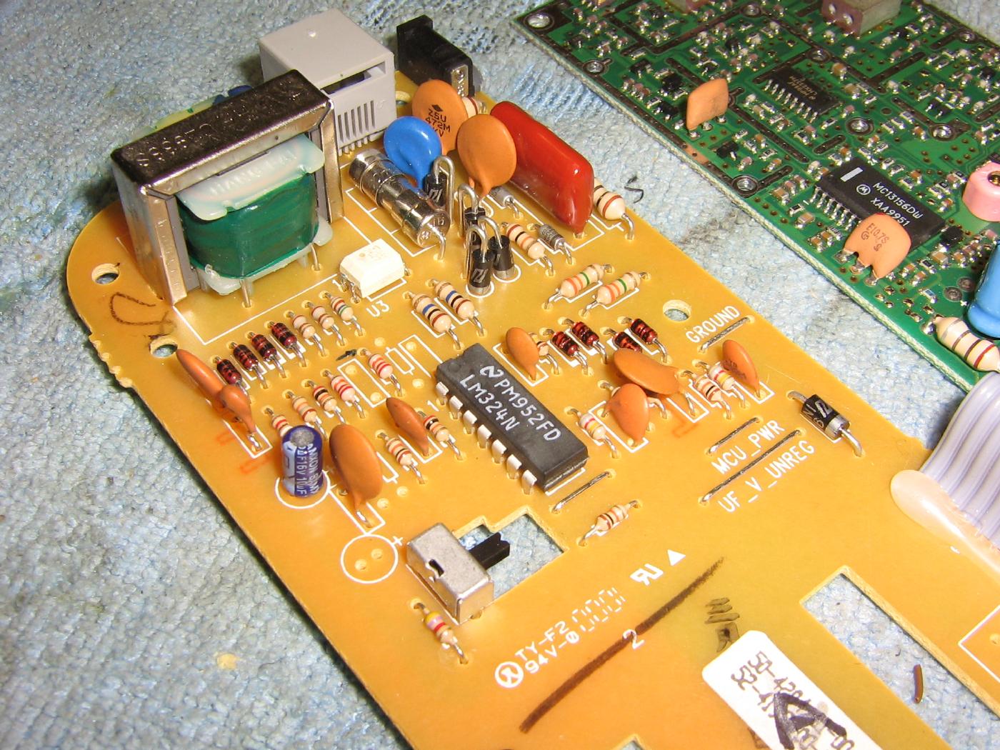
Telephone line interface circuit board of the Sony SPP-ID910.
The final decoded audio will be taken from pin 1 of the LM324 shown above and sent to a front-panel BNC jack.
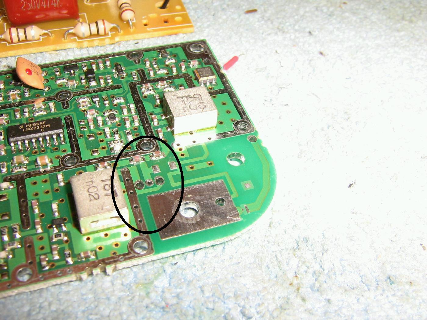
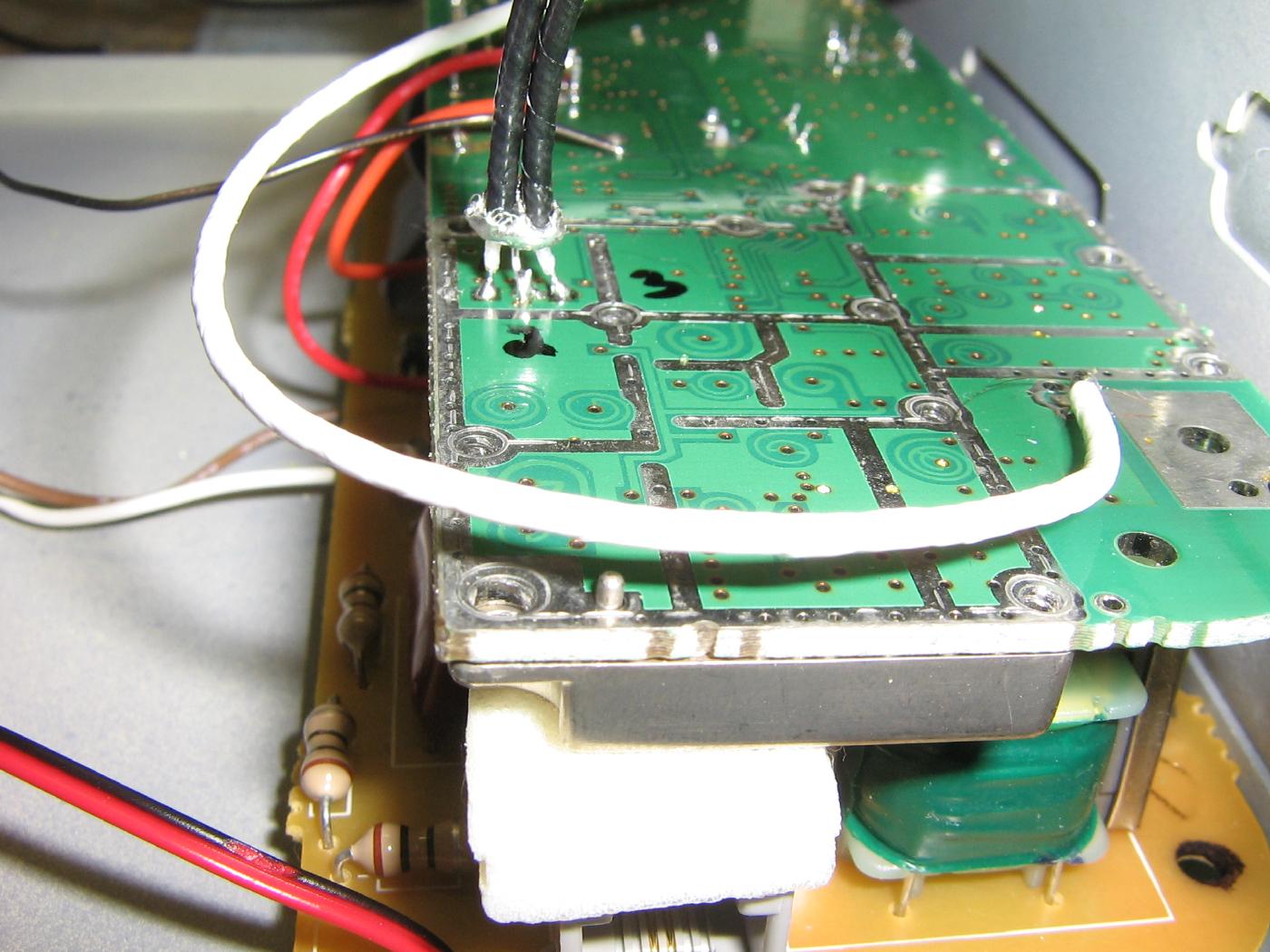
You'll want to add an external antenna to the base station.
Do this by unsoldering the 0-ohm jumper on the circuit board which connected to the pad for the stock "rubber duck" antenna.
Solder in a piece of small-diameter 50 ohm coax into the plated holes, which are circled above.
The center conductor of the coax should go to the center hole. The other holes are ground and should be soldered to the coax's shield.
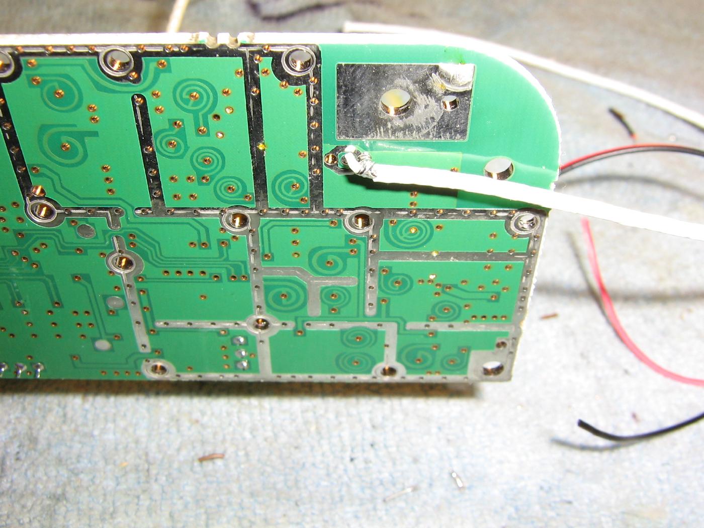
Attaching a piece of coax for the external antenna SMA jack.
I ended up soldering the coax to the bottom of the board, which was required for the final mounting arrangement used here.
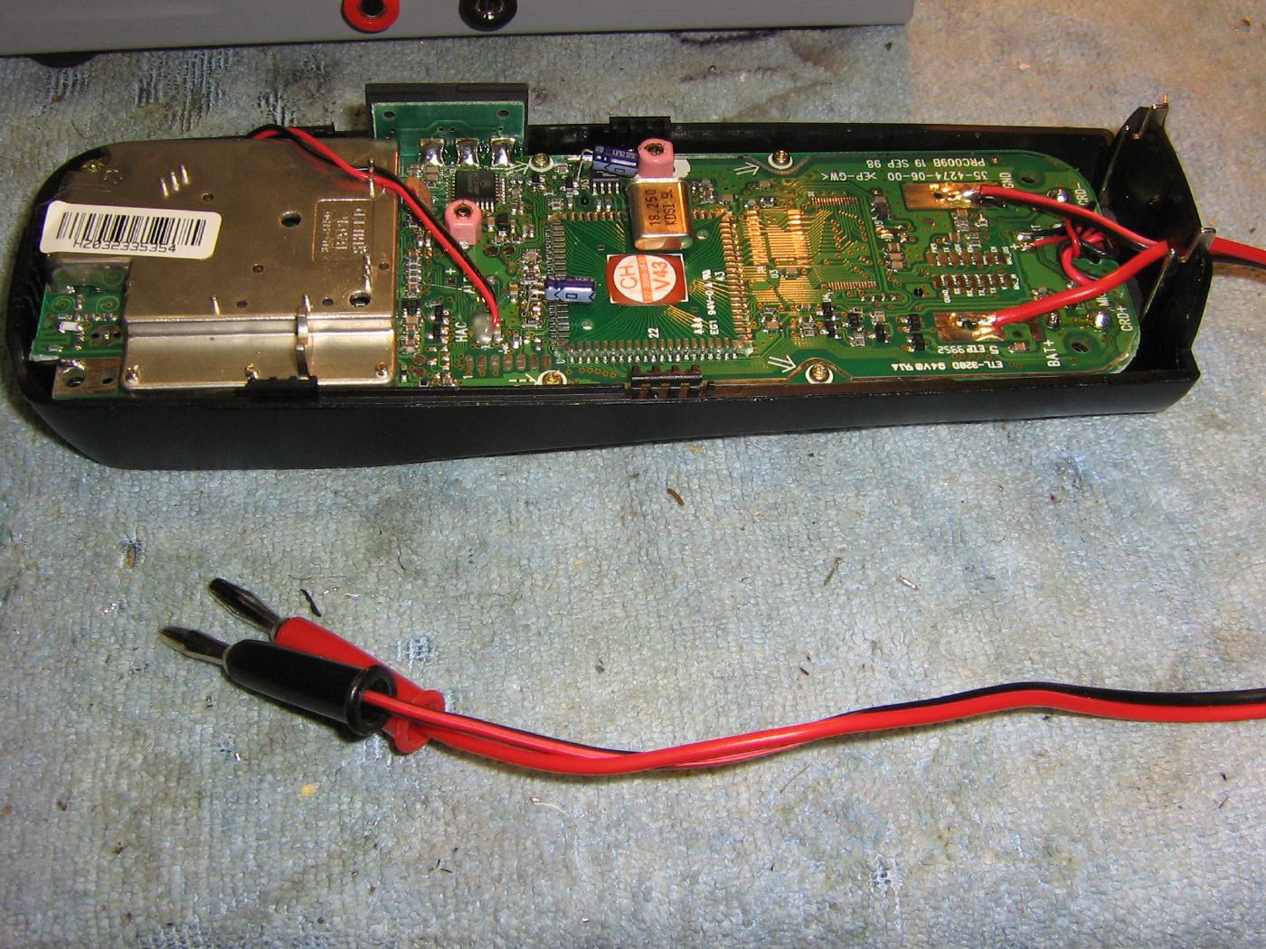
The handset requires no real major modifications.
Solder two pieces of wire (with banana jacks) to the solder pads which held the battery springs. This is for applying the handset's required +5 VDC remotely.
Also, the stock antenna was replaced with a short little piece of wire.
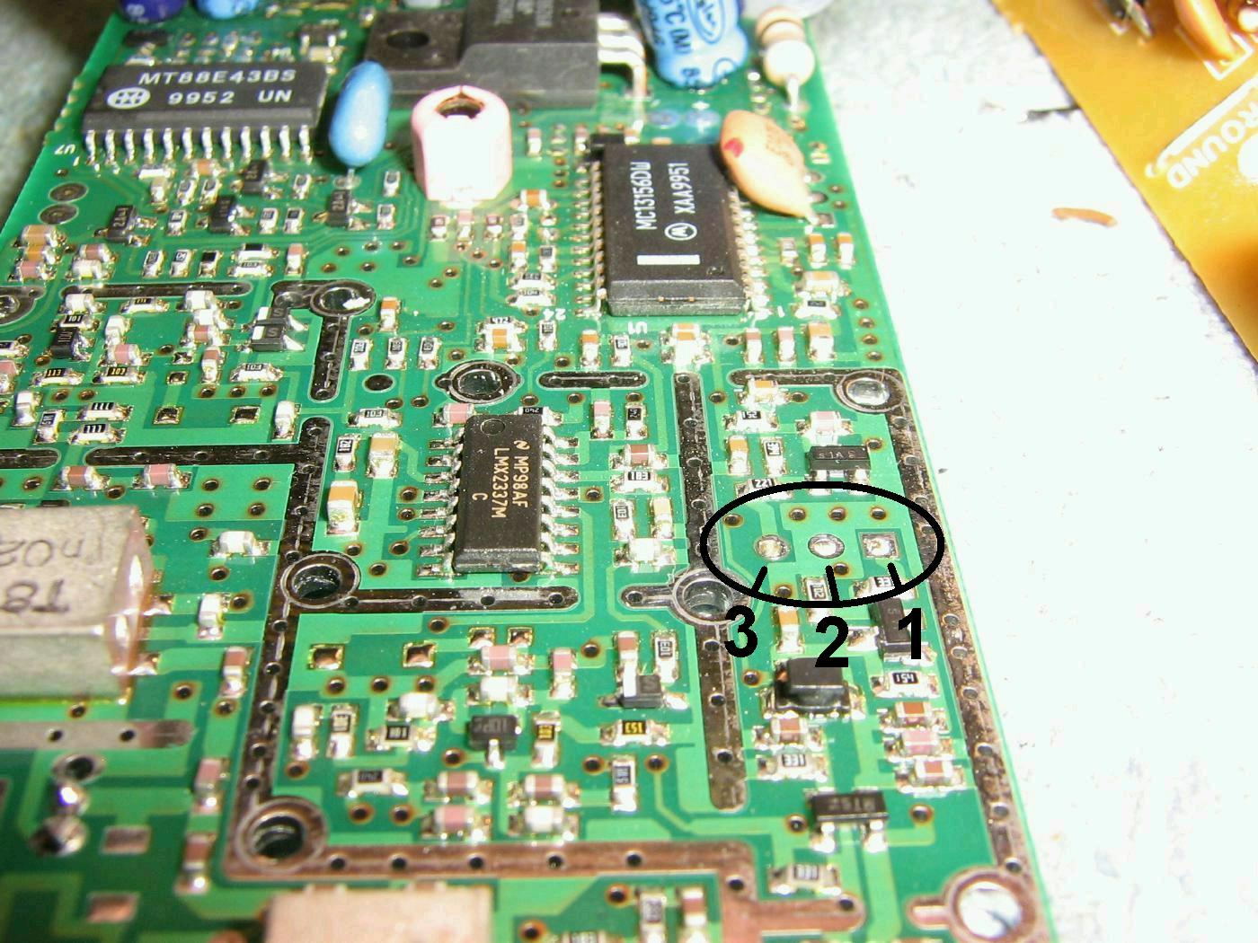
Removing the base station's first 10.7 MHz IF filter.
Save this filter for use in the RF relay circuit, which will be described later.
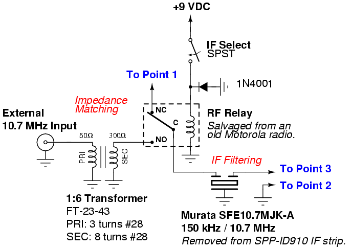
Point 1 is the output from the base station's stock receive mixer containing the 10.7 MHz signal.
Point 2 is a common ground.
Point 3 is the 10.7 MHz input to the MC13156 wideband IF chip.
Attaching small diameter 50-ohm coaxial cables to the input/output pads where the 10.7 MHz ceramic filter used to be.
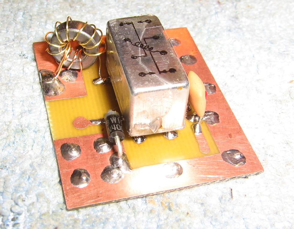
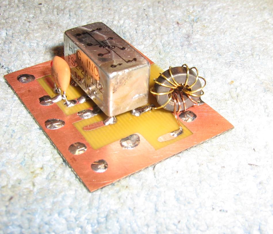
The RF relay which selects between the phone's stock 10.7 MHz IF and an external 10.7 MHz IF.
These RF relays can be found in some older Motorola two-way radios.
The input matching transformer is on the upper-left. It's used to convert the 50 ohms input to the 300 ohm impedance of the 10.7 MHz ceramic filter.
The ferrite torroid is an Amidon FT-23-43 with 3 turns of #28 enamled wire on the primary and 8 turns of #28 enamled wire on the secondary.
Alternate view of the RF relay and impedance matching circuit.
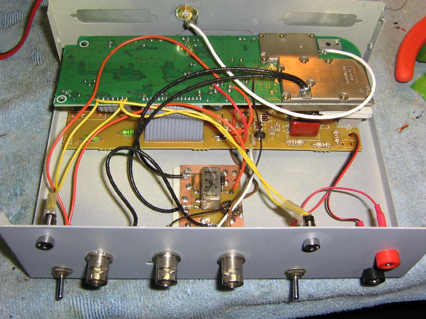
Completed internal view.
The front-panel BNC connectors are for an external 10.7 MHz input, MC13156 data slicer output, and audio output.
The banana jacks on the right are for the +9 VDC power the unit requires.
The LED on the left is from the "Line Enable" on the sub-circuit of the base station. The other LED is a power indicator.
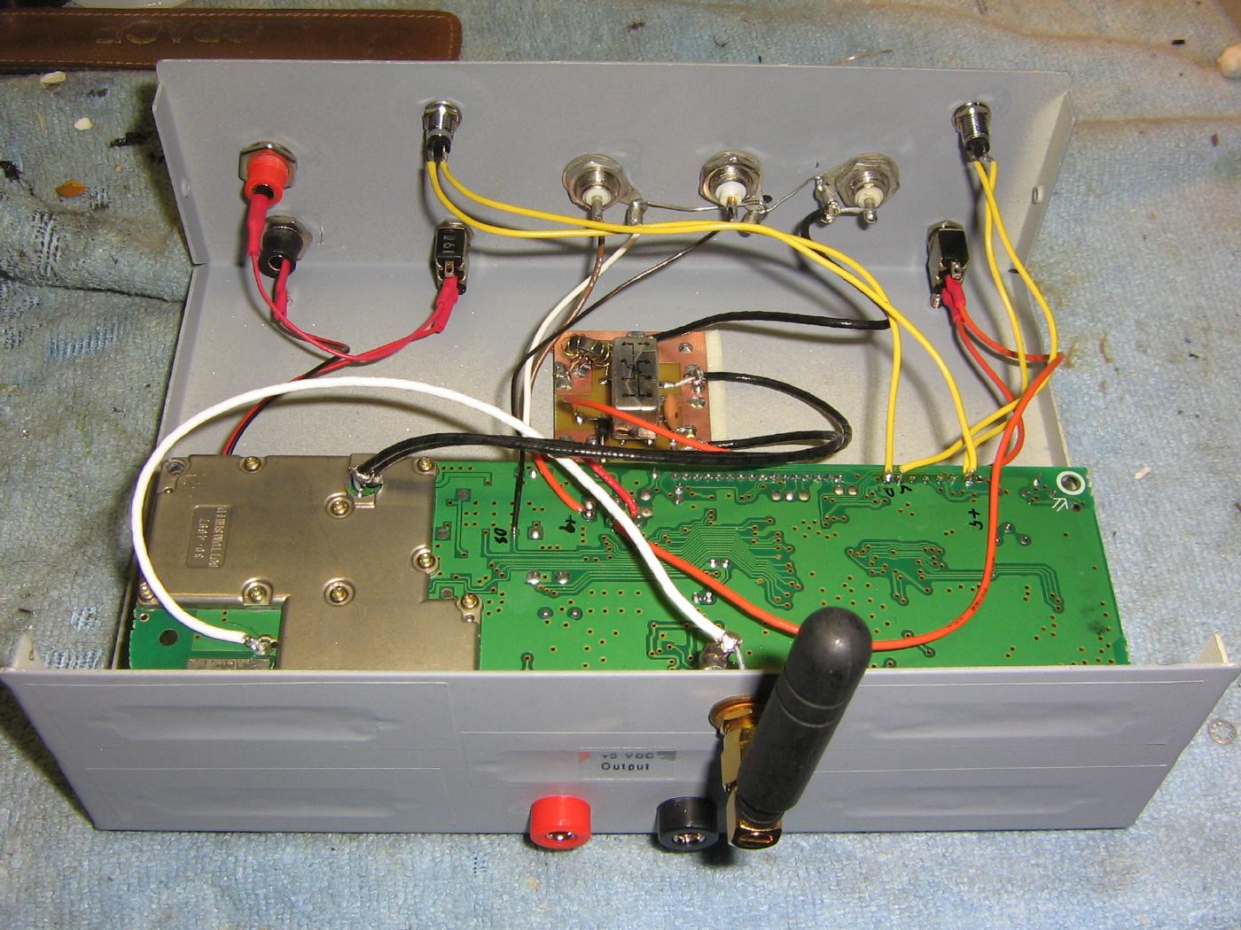
Alternate overview showing the rear panel.
A SMA jack is for an external antenna.
The banana jacks along the bottom provide the +5 VDC output for powering the handset. Tap the output of the 7805 voltage regulator on the base station's main circuit board.
Optionally, tap pin 17 on the Motorola MC13156 (or pin 75 on the AMD AM79C490) to provide a data slicer output signal. This should go to a panel-mounted BNC jack.
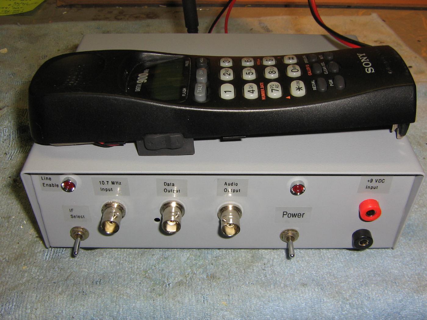
Completed overview.
To use this device, apply +9 VDC power to the front-panel banana jacks. This will power both the base station unit and the handset.
Be sure the "IF Select" switch is set to the internal 10.7 MHz IF of the phone.
After a few seconds, the handset and base station should sync, displaying "CHANNEL SEARCHING..." and which channel they are using.
Press the "TALK" button on the handset and the "Line Enable" LED should light. The handset will now display "PHONE ON".
Flip the "IF Select" switch to choose an external 10.7 MHz containing your target data modulation. If it contains audio encoded by a similar Sony/VTech digital cordless phone, the line-level audio will be available on the "Audio Output" BNC jack.
If no audio is available, then it's possible to take the raw data stream from the "Data Output" BNC jack and apply some further external processing via hardware or software. This is should be handy for decoding pagers...
View the MC13156's datasheet for a more in-depth discussion of the MC13156's FSK data decoding possibilities.
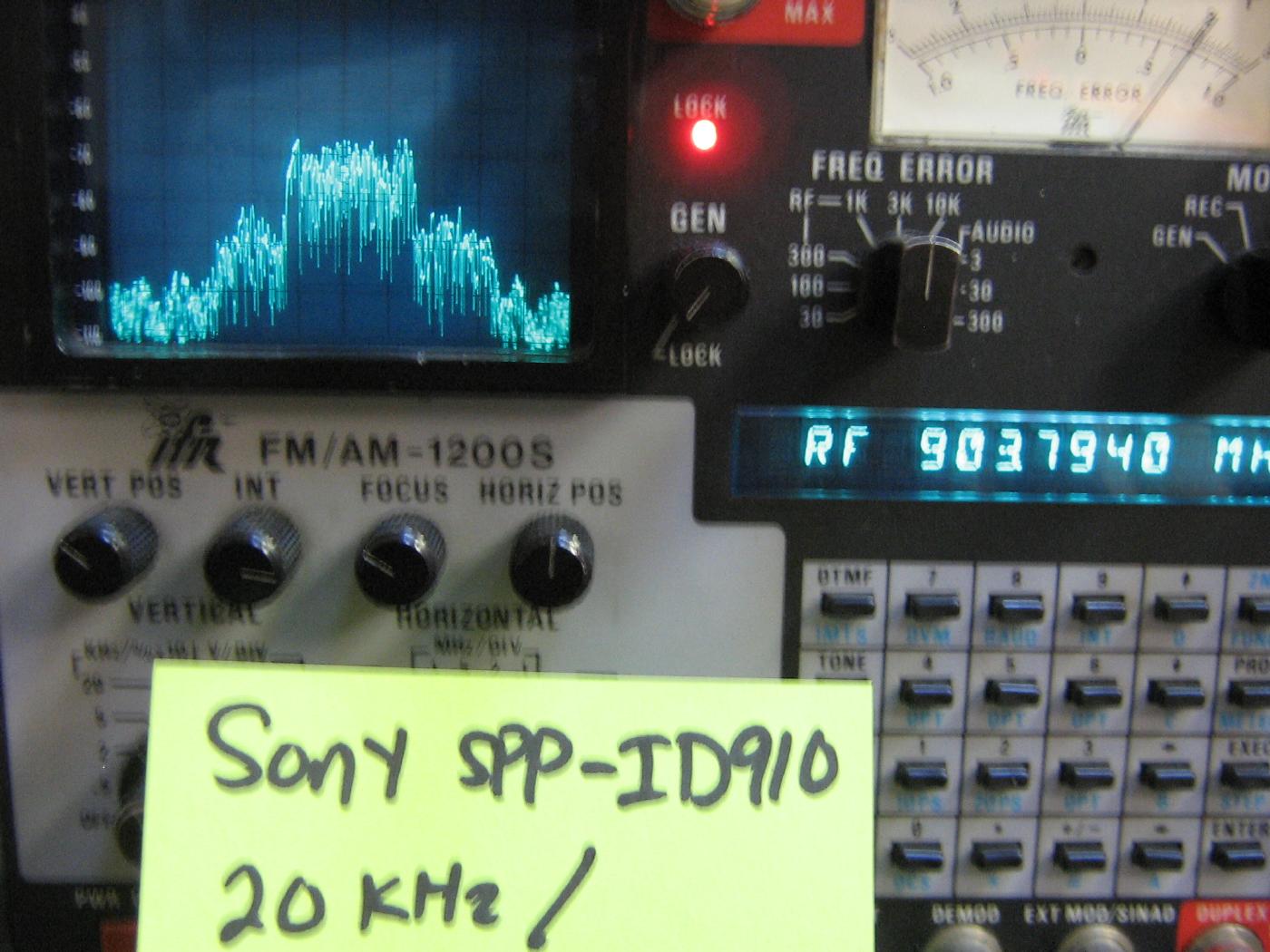
IFR FM/AM-1200S spectrum analysis of a Sony SPP-ID910 900 MHz digital cordless phone in operation.
The center frequency of the base station is at 903.8 MHz. The spectrum display is 20 kHz per horizontal division.