70 cm 6/8 Element Beam
Based on a design from Clear
Lake Amateur Radio Club. They have an article
posted from one of their newsletters describing some loose tolerance multielement
beam antennas. I took one of the designs (for 432 MHz) and built it for use
as an ATV receiving antenna. The boom is made from scrap 1/2" PVC pipe
and 1/8" brass rod for the elements. It turns out that bending the rod
to the necessary 3/8" spacing for the matching network is pretty difficult,
but a vise, pliers, and some leverage got it there. My real concern is the bandwidth
of the longer antenna might be too narrow for the video, which is 5 MHz wide.
(this is probably unfounded, now that I've done some modeling, shown below).
Here the dimensions from their web page for the 432 and 435 MHz versions are
below. Notice that the difference in element lengths is just a tenth of an inch
for the reflector and first director.
432 MHz. This antenna is peaked for 432.1 MHz. At this frequency, this
antenna is getting very practical and easy to build. Driven element dimensions are L =
13.0" and H = 3/8" Elements are 1/8" diameter.
| 432MHz |
REF |
DE |
D1 |
D2 |
D3 |
D4 |
D5 |
D6 |
D7 |
D8 |
D9 |
| 6 Element |
Length
Spacing |
13.50
0.00 |
2.50 |
12.50
5.50 |
12.00
11.25 |
12.00
17.50 |
11.00
24.00 |
|
|
|
|
|
| 8 Element |
Length
Spacing |
13.50
0.00 |
2.50 |
12.50
5.50 |
12.00
11.25 |
12.00
17.50 |
11.00
24.00 |
12.00
30.75 |
11.25
38.00 |
|
|
|
| 11 Element |
Length
Spacing |
13.50
0.00 |
2.50 |
12.50
5.50 |
12.00
11.25 |
12.00
17.50 |
11.00
24.00 |
12.00
30.75 |
12.00
38.00 |
11.75
45.50 |
11.75
53.00 |
11.00
59.50 |
435 MHz AMSAT. The larger versions have not been fully tested and I
appreciate the help and motivation from KA9LNV for these antennas. Updates and performance
evaluations are planned for a later edition of the AMSAT Journal. A high Front-to-Back
ratio was the major design consideration for all versions. The computer predicts 30 dB F/B
for the 6 element and over 40 dB for the others. NEC predicts 11.2, 12.6, 13.5 and 13.8
dBi for the 6, 8, 10 and 11 element respectively. Using 3/4" square wood makes it
easy to build two antennas on the same boom for cross- polarized operation. Offset the two
antennas 6 1/2" and feed in phase for Circular Polarization. Or, just build one
antenna for portable operation. Driven element dimensions are L = 13.0" and H =
1/2" Elements are 1/8" diameter. Spacing is the same for all versions.
| 435 MHz AMSAT |
REF |
DE |
D1 |
D2 |
D3 |
D4 |
D5 |
D6 |
D7 |
D8 |
D9 |
| 6 Element |
Length |
13.40 |
|
12.40 |
12.00 |
12.00 |
11.00 |
|
|
|
|
|
| 8 Element |
Length |
13.40 |
|
12.40 |
12.00 |
12.00 |
12.00 |
12.00 |
11.10 |
|
|
|
| 10 Element |
Length |
13.40 |
|
12.40 |
12.00 |
12.00 |
12.00 |
12.00 |
11.75 |
11.75 |
11.10 |
|
| 11 Element |
Length
Spacing |
13.40
0.00 |
2.50 |
12.40
5.50 |
12.00
11.25 |
12.00
17.50 |
12.00
24.00 |
12.00
30.50 |
11.75
37.75 |
11.75
45.00 |
11.75
52.00 |
11.10
59.50 |
NEC modeling
Here's the NEC model:
CM 70cm Beam, based on 432 MHz design from Clear Lake Amateur Radio Club
CM ( http://www.clarc.org/Articles/uhf.htm )
CM 110 mm in diameter, 5.5 turns, 2.54 mm (AWG 10) conductors
CM boom ignored in this model
CM Elements are 1/8" diameter brass rod (conductivity 15.5E6 mho/meter, viz copper 58)
CM Pattern at 434 and 426.25 (ATV frequencies in So Cal)
CM SZ 1800,0
CE Gain evaluated at 420 through 450 MHz
GA,301,5 ,0.004763,-90,90,0.001588
GM,0,0, 90,0,0, 0.1603,0.004763,0.0635
GW,999,1, 0,0,0.0635, 0,0.009525,0.0635,0.001588
GW,201,21,  0,0.009525,0.0635, 0.1603,0.009525,0.0635,0.001588
GW,100,21,0.1715,0,0.0000, -0.1715,0,0.0000,0.001588
GW,101,11,0.1603,0,0.0635, 0,0,0.0635,0.001588
GW,401,11, 0,0,0.0635, -0.1651,0,0.0635,0.001588
GW,102,21 ,0.1588,0,0.1397, -0.1588,0,0.1397,0.001588
GW,103,21 ,0.1524,0,0.2858, -0.1524,0,0.2858,0.001588
GW,104,21 ,0.1524,0,0.4445, -0.1524,0,0.4445,0.001588
GW,105,21 ,0.1397,0,0.6096, -0.1397,0,0.6096,0.001588
GW,106,21 ,0.1524,0,0.7811, -0.1524,0,0.7811,0.001588
GW, 107,21,0.1429,0,0.9652, -0.1429,0,0.9652,0.001588
GE
EK
LD,5,0,0,0,1.55E+7
PT,-1
EX,0,999,1,1,1,0
FR,0,30,0,0,420,1
XQ,3
EN
Generating the NEC files was made substantially easier by using an Excel spreadsheet
(clarc.xls 21KB) to generate the
geometry cards for the NEC input file.
After some NEC2 modeling runs, I have come up with the following interesting
data:
| Configuration |
2:1 VSWR Bandwidth (approximate) |
Pattern
| Freq |
gain
dBi |
E plane (az)
3dB BW |
H plane (el)
3dB BW
|
|
| 432 6 el ideal |
423 - 433 |
427, 11.11
435, 10.22 |
| 432 6 el brass |
423 - 433 |
| 427 |
10.02 |
51 |
63
|
| 435 |
10.09 |
49 |
59 |
|
| 432 8 el ideal |
424.5 - 430.5 |
427, 11.5
435, 11.63
|
| 432 8 el brass |
424.5 - 431.5 |
| 427 |
11.38 |
40 |
49
|
| 435 |
11.45 |
40 |
45 |
|
Obviously, one can't trust the numbers to the nearest 0.01 dB, but it gives
an idea of the sensitivity of the gain to variation in frequency. The relatively
small variation is good, implying that the design is non critical. It also appears
that the effect of loading by the brass is to slightly increase the 2:1 VSWR
range (a good thing). On the higher gain antenna, where the loss would have
a greater effect, the gain is reduced by about 0.2 dB, a practically insignificant
amount. On the lower gain (6 element) antenna, it looks like the loss reduces
the gain by more than 1 dB for the lower frequency, and about 0.13 dB for the
higher frequency. It might be worth repeating the model for the 427, because
it is a suspiciously big change. The antennas have a bit higher gain at the
higher frequency, but, particularly for the 8 element, the match is worse, so
the net effect might be to even out.
The frequencies 427 and 435 were chosen to represent roughly the middle of
the video signal at 426.25 and 434.
Note that in vertically polarized ATV operation, the E plane is vertical and
the H plane horizontal. These antennas have a wider H plane pattern than E plane,
which is a good match to my robot ATV operation, since the narrow vertical beamwidth
will help reduce multipath from the low mounted vertical whip.
Obviously, changing to a CP version would improve this even more, and is something
I am contemplating, after some field tests. I have the bucket lindenblad design
for the robot, and it would be easy to make a CP version of the beam antenna.
Photos
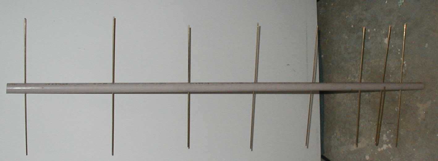
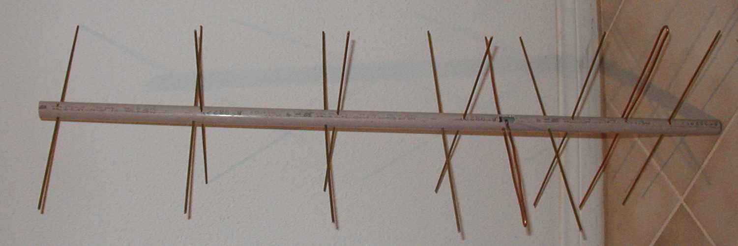
The following are clickable thumbnails of some photographs of the original
8 element antenna, and then the 6 element version, with a crossed copy offset
by 1/4 wavelength to make a circularly polarized.
|
Original 8 element linear polarized beam. One of the elements looks bent,
and probably is.
(33KB jpg)
|
 |
|
Modified for 6 elements, dual antennas offset by quarter wavelength.
In this one, the driven element is AWG 8 copper wire (because I ran out
of brass rod, and I broke one of them building it).
(39KB jpg)
|
 |
/radio/beam70cm.htm - 31 Aug 2002 - mail to
Jim Lux
antenna home page - radio home
page - Jim's home
page