Phased arrays are greatly affected by the mutual impedances between the elements, which can have a large effect on the element currents if the feed network doesn't take them into account.For instance, in most arrays, even if the element currents are the same, the element powers are not.
There are a number of equations to calculate the mutual impedances, with varying degrees of fidelity, and for various configurations of dipoles in various orientations and relative positions. One can also use antenna modelling programs to calculate the mutual impedances even more accurately. I'm not sure that calculating to that degree is necessary, because the realities of construction precision and siting will probably have larger effects.
Note also that the impedances at a phasing network will most likely be affected by the transmission lines. (transmission line equations)
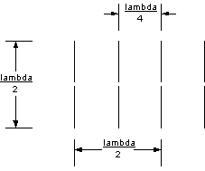
Consider a linear array of 4 parallel half wave dipoles, spaced at 1/4 wavelength. (See here for a square array of parallel dipoles.)

The self impedance is 72+j40 ohms (in normal use, the dipole would be cut slightly short to remove the reactive component). The mutual impedance to elements some distance away is calculated (and rounded to the nearest ohm) as:
| Self | 72 + j40 |
| 1/4 Wavelength | 41 - j30 |
| 1/2 Wavelength | -13 - j25 |
| 3/4 Wavelength | -20 + j5 |
From these numbers we can construct a 4x4 matrix [Z] of self and mutual impedances among all 4 elements. This matrix is used in the equation:
[E] = [Z][I]
where [E] is the vector of feed point voltages, and [I] are the feed point currents. For pattern synthesis, we want to assume a specified current distribution that will produce the desired radiation pattern. For instance, a simple distribution creates an "end fire" pattern: each element current has magnitude 1 amp, and phased in 90 degree steps for each element. This results in the following feed point voltages which we can divide and multiply by the feed point current get the feed point impedances and powers. Apparent power is the product of the magnitude of voltage and current.
| 1 | 2 | 3 | 4 | |
| Voltage | 120+j50 | 15 + j 85 | -85 + j 15 | -80 + j 50 |
| True Power (Watts) | 120 | 85 | 85 | 50 |
| Reactive Power (Vars) | 46 | -15 | -15 | -76 |
| Apparent Power (VA) | 128 | 86 | 86 | 91 |
| Feedpoint Impedance | 120+j 50 | 85 - j 15 | 85 - j 15 | 50 - j 80 |
Note that the total power of 340 watts is not divided equally among the elements; this is why phased arrays, in general, don't want to use an N-way power divider. Compare this to a single dipole (72+j40) with 1 amp flowing in it: E = 72 - j 40, true power is 72 watts, with a reactive power of -40 var.
Another trivial case, a broadside pattern with all elements fed in phase, produces some interesting feed characteristics.
| 1 | 2 | 3 | 4 | |
| Voltage | 80 - j 90 | 141 - j 125 | 141 - j 125 | 80 - j 90 |
| True Power (Watts) | 80 | 141 | 141 | 80 |
| Reactive Power (Vars) | -90 | -125 | -125 | -90 |
| Apparent Power (VA) | 120 | 188 | 188 | 120 |
| Feedpoint Impedance | 80 - j 90 | 141 - j 125 | 141 - j 125 | 80 - j 90 |
Again, we have an uneven power distribution: 1:1.76:1.76:1. The moral of the story is that because of mutual impedances, the power is rarely distributed evenly among the elements, even if the current is. Remember, we want to control the current distribution, because that is what controls the pattern.
mutualz.htm - Revised 25 Nov 2000, Jim Lux
back to Phased Arrays | antenna
home | radio home | Jim
Lux home
email comments jimlux@earthlink.net