Distributing the Power
One of the results you get after having determined element currents and
applying the mutual impedance matrix is the power flowing to or from each
element. Given that the matching and delay network is lossless, this is
the same power that must flow to or from the summing point at the radio.
Further, you generally want to have a resistive 50 ohm termination for
the radio to look at. This is actually quite easy to achieve.
The network which determines the phase shift can also transform the
resistive impedance of the antenna matching network to whatever is necessary
to achieve proper power distribution.
Taking the easy case first, assume you want an even distribution of
power. You would calculate the delay network to have an input impedance
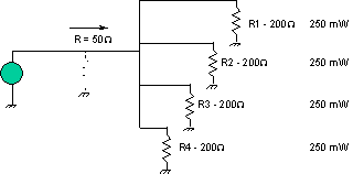
equal to 50*N ohms, where N is the number of elements. The figure below
illustrates this for 4 elements. Each network would be adjusted so
that it looked like a 200 ohm resistive impedance. When all the 200 ohm
impedances were paralleled, the impedance that the transmitter sees is
50 ohms.

However, in general, the power is not divided evenly. In this case,
you need to adjust the input impedances so that two constraints are met:
-
The parallel combination of them all has to be 50 ohms resistive; and
-
the impedances are inversely proportional to the power to be distributed
to that element.
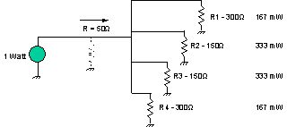
The following diagram shows how this would be done where you wished
two elements to receive twice the power of the other two. Note that the
parallel combination of the load resistances adds up to 50 ohms, and that
the power dissipated in each load resistor is distributed appropriately.

The equation which determines the required load impedance for each element
is:
Negative Source Impedances - Negative Element Power
In some phased array set ups, a condition where negative power is consumed
by an element occurs; that is, an element actually absorbs power from the
other elements. With a lossless matching network, this power can be fed
to the other elements, so nothing is really lost. This is accomodated quite
easily by assuming that the load impedance is negative.
pwrdiv.htm - revised 11 March 1999, Jim Lux
return to Passive Beamforming
back to Phased Arrays
radio home
Jim Lux home
email comments jimlux@earthlink.net


