Think of an antenna with adjustable beamwidth, deep nulls that can be placed on interfering signals, and that can be redirected to any azimuth and elevation in milliseconds. And, as a benefit, you don't need to have a huge rotating thing up in the air, where the homeowner's association gets mad. The answer is a phased array.
What is that big 5 element beam but a phased array with the element currents determined by the mutual impedances between the driven and parasitic elements? Rather than move the elements around to move the beam, why not move the currents, and leave the elements where they are. Theoretically, it is the physical size of the antenna that determines the directivity/gain, not the precise arrangement of the elements. Imagine then, putting active elements over the entire roof of the house, covering a distance of 30x60 feet. Efficiency (ground losses) aside, you should be able to get patterns from this array comparable to those from a beam of comparable dimensions (which is pretty darn big).

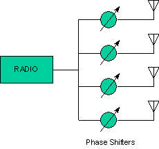
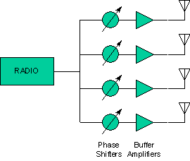
The problem in any phased array is getting the phase and magnitude of the currents in each of the elements to be properly set to produce the desired pattern. When the elements have large mutual impedances, this can prove to be quite tricky. The easy way out is to provide separate driver amplifiers (for transmit, buffers for receive) for each element, and rely on the isolation provided by the amplifiers between the active elements and the phasing network. There are some potential problems with elements that have negative feed impedances, but in general, this is the optimimum solution.

This is the ultimate scheme, and one which I am working on for the future: small solid state drivers at each element for transmit, H field current probes for receive, and DSP to do all the phasing and beamforming. I've done some preliminary design work on this approach, which is described in more detail in Active Beamformers[active1.htm - MISSING].
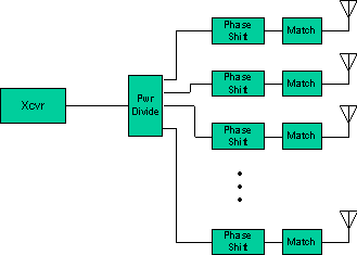
However, for now, the project is to to use an existing transciever and use some sort of passive network to do the beamforming. There have been a variety of amateur radio attempts to build passive beamformers, most recently relying on the "current forcing" properties of quarter wave transmission lines. A more complex, but ultimately flexible approach is the one used in the broadcast industry, using a multitude of networks. This is the approach I am taking with Passive Beamformers.

Gain - how much gain do you really need. Lets consider both receive and transmit: On receive for HF work, in the vast majority of cases, you are limited by atmospheric noise, not receiver noise, so a preamp can make up for any losses in the antenna. On transmit, you can always run more power.
Directivity - This is what you really need. Particularly on receive, directivity is what lets you knock down the QRM by pointing the antenna where the interfering signals arent. By the way, the ability to place nulls independently of the main lobe is a big advantage of a phased array. This is why the emphasis on front/back ratios on beams On transmit, you don't need as much directivity. If you squirt your power in too many directions, you just need to run more power to get enough power in the right direction. Much of the performance of a long boom beam is due to the vertical directivity, as much as the horizontal directivity. You aren't squirting power up into the sky or down into the ground. The increased vertical directivity also reduces the effect of non-ideal ground.
Efficiency - This is sort of related to gain. On transmit, a physically small radiator is going to be inefficient. On receive, it just doesn't intercept as much power. Both of these are fixable in the HF area: more power in the case of transmit, preamps in the case of receive.
1) Half the power goes into the main lobe, half the power goes into all the sidelobes together. If your main lobe is, say, 30 degrees wide (in both planes), the gain of the antenna will not be 16.6 dBi (directivity of 45) , but more like 13.6 dBi. Of course, the power density in the "non main lobe" area will be much lower (1/45th or -16 dB), but it is non-zero. In this example, the gain, outside the main beam, would average around -3 dBi (which is true of most real antennas).
2) The basic gain of the antenna will be proportional to the number of elements, providing the elements aren't too close together. That is, if you have two elements, your gain will be 3dB, with 3 elements 5 dB, and so forth. Theoretically, you can get a gain of 6*N dB, since you are coherently combining the signals, however, such superdirective arrays tend to have high losses and ugly patterns.
3) Each element has a "capture area" of about (wavelength/2)^2. Place the elements closer together, and the gain won't be as high as it would with them farther apart. As a practical matter, though, you put them closer because gain isn't everything (in fact, it is almost immaterial), and closer spacings give you better control over the pattern.
So, what sort of performance should we shoot for.
Typical high performance long boom beams have gains of around 12-13 dBi. Their front to back ratio is typically around 20-25 dB, which essentially determines the required null depth for your phased array. Their directivity will be around 45-50, which implies that there are 50 or so orientations that are useful (25 actually, considering it you have to cover a hemisphere, but double it because it lets you space the positions closer than the -3 dB points).
Calculations of mutual element impedances are essential
for phased arrays
Calculating the patterns
Passive Network analysis
Papers by Grant Bingeman, P.E., KM5KG: