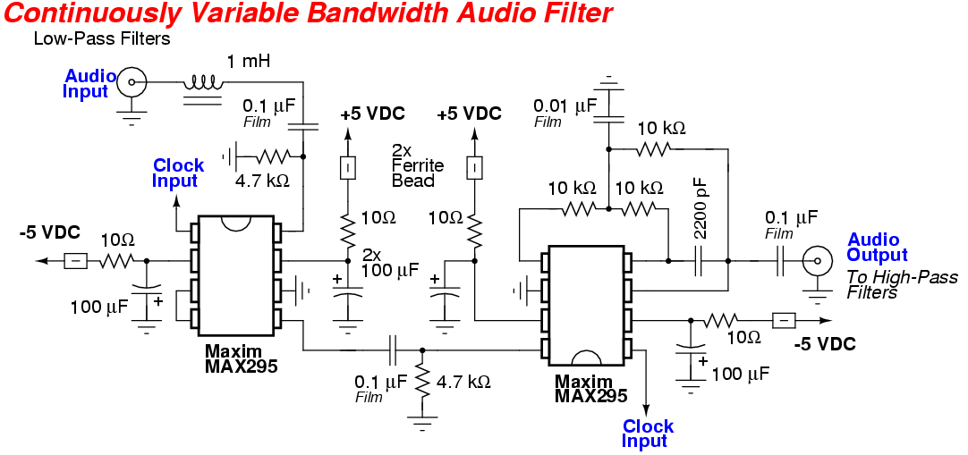
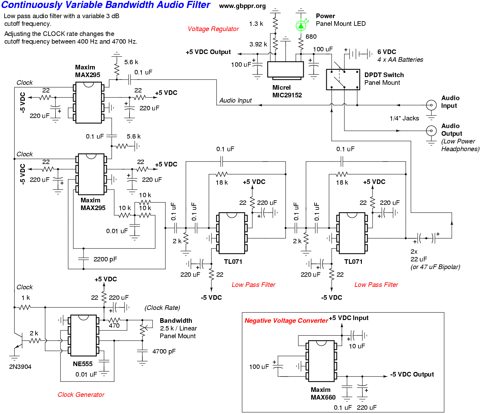
This is a high-performance switched-capacitor audio filter based around two Maxim MAX295 8th-order Butterworth filter ICs and a couple of TL071 op-amps. The Maxim MAX295s each have an approximately 48 dB/octave dropoff at their low-pass cutoff frequency and will provide a maximum out-of-band attenuation of almost 100 dB. This filter is ideal for just about eliminating any high frequency audio hiss and also greatly attenuating any 60/50 Hz hum on an incoming audio signal.
This project is an updated design based on an article by Denton Bramwell (K7OWJ) which originally appeared in the July 1995 issue of QST. A copy of that original QST article will appear at the end of this article.
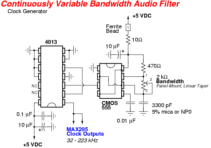
The 3 dB low-pass Frequency Cutoff (Fc) of the two MAX295s is controlled with a simple variable clock generator based around the standard 555 timer IC. The 3 dB low-pass cutoff of the MAX295 filters in this circuit design can be varied from approximately 640 Hz to 4500 Hz. This is an ideal range for most "speech frequency" specific audio applications. The MAX295 is capable of handling signals up to around 50 kHz. The MAX295's Fc is equal to the input clock rate divided by 50. For example: If the 555 timer is set to 165,000 Hz (165 kHz) then the MAX295's low-pass cutoff frequency will be 3300 Hz.
Because the MAX295 like to see a clock frequency with a 50% duty cycle, a 4013 flip-flop will be added on the output of the 555 timer to provide this. The 4013 flip-flop generates a clean 50% duty cycle square wave regardless of the duty cycle of the driving 555 timer clock signal.
The flip-flop "divides-by-2" its input signal, so take this into account if you need to redo the timing resistors/capacitor for the 555 timer. The final frequency output of flip-flop in this circuit will be variable from around 32 kHz to 223 kHz.
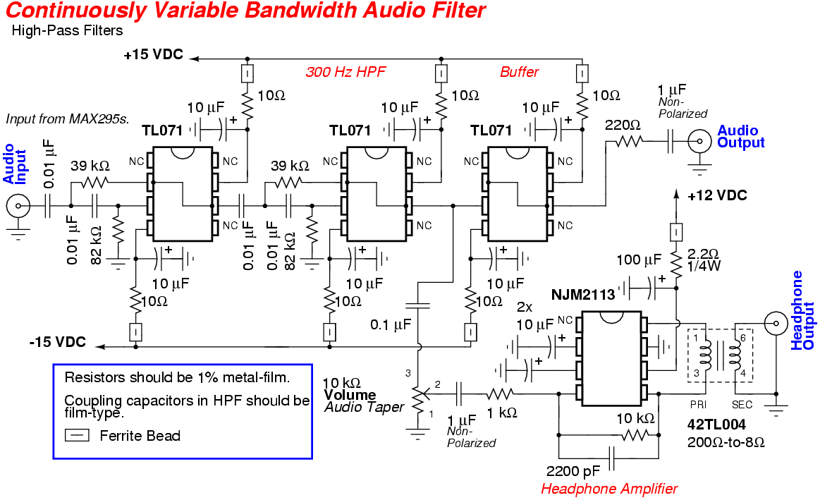
The TL071 op-amps are for additional high-pass filtering (300 Hz) of the audio signal. They are not really needed, but it is highly recommended to add a little bit of high-pass filtering to the audio chain. One of the TL071 op-amps is configured to act as a buffer for the final output signal.
A JRC NJM2113 (or Motorola MC34119) low-noise audio power amplifier was added for driving standard low-impedance (8/16/32 ohm) headphones or a speaker. An isolation transformer isolates the 1/8-inch headphone jack from the metal case of the project box.
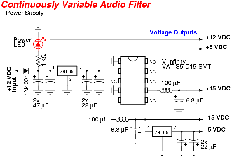
The two MAX295s have a fairly high negative voltage current draw (25 mA), so a V-Infinity VAT1-S5-D15-SMT switching negative (+/- 15 VDC) voltage converter will be used to generate the negative voltage. Standard 7660-type negative voltage generators are not recommended as they will "droop" under the high current load, plus they'll add additional in-band switching noise to the final audio signal.
The TL071 op-amps will be run at +/- 15 VDC for maximum dynamic range and to avoid any audio clipping. A 79L05 negative voltage regulator will be used to provide the -5 VDC for the MAX295s from the -15 VDC rail.
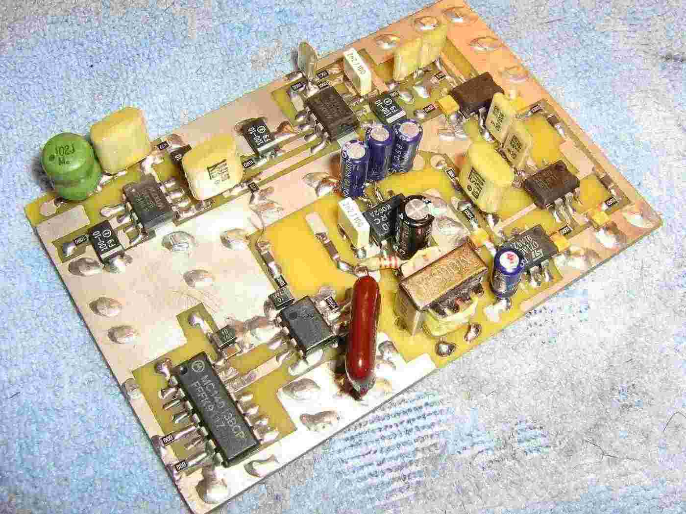
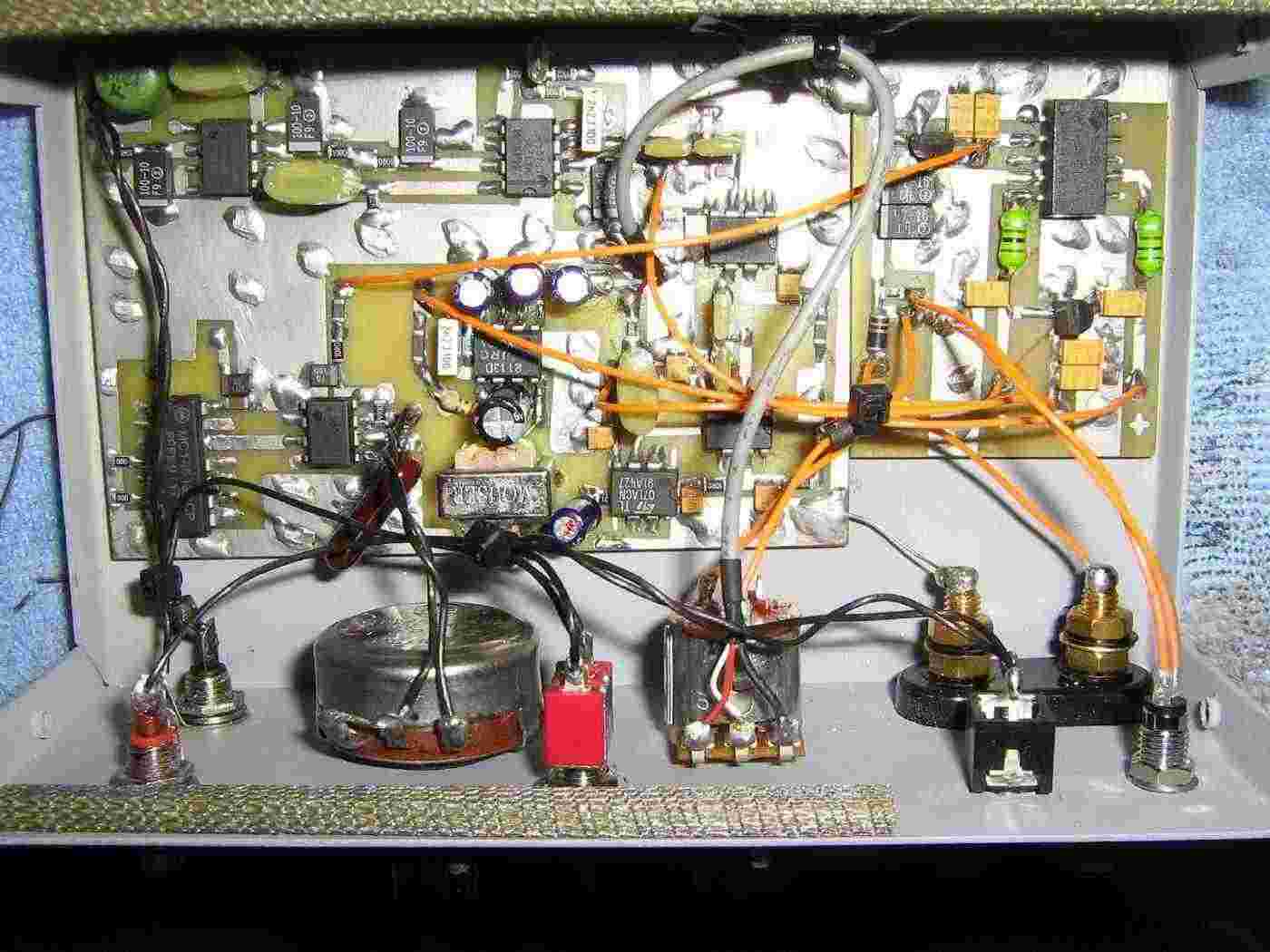
Overview of the Continuously Variable Bandwidth Audio Filter circuit board.
The 4013 and 555 timer for the clock generator are on the lower-left. By pure luck I managed to find a 1% tolerance 3300 pF silver mica capacitor (the reddish-brown thing) for the 555 timer. This will help to significantly stablize the final output clock signal. Try to find a capacitor with at least a 5% tolerance over a wide temperature range.
The two Maxim MAX295s are along the top of the circuit board. Metal-film resistors and polystyrene capacitors were used in the coupling stages for maximum performance. An optional 1 mH inductor on the audio input signal helps to knock down any low-frequency RF noise on the incoming audio signal.
The TL071 op-amps for the 300 Hz high-pass filters are along the right-side of the PC board.
The NJM2113 low-noise audio power amplifier is in the middle, with a Mouser 42TL004 200-to-8 ohm matching transformer on its output. This is required to isolate the headphone jack from the metal of the case.
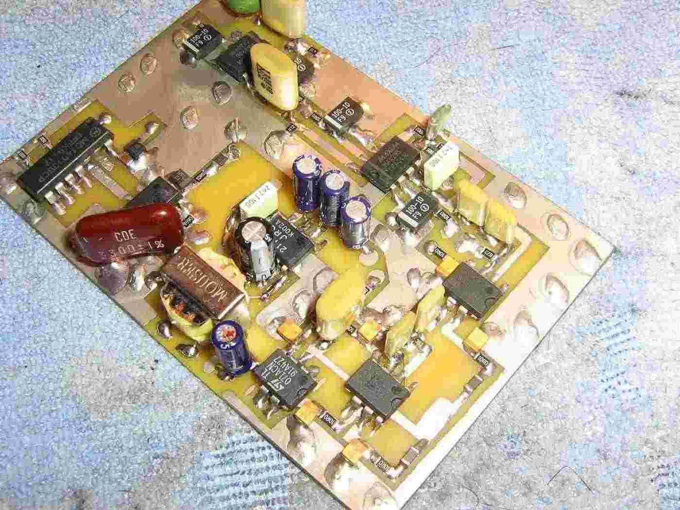
Alternate view of the Continuously Variable Bandwidth Audio Filter circuit board.
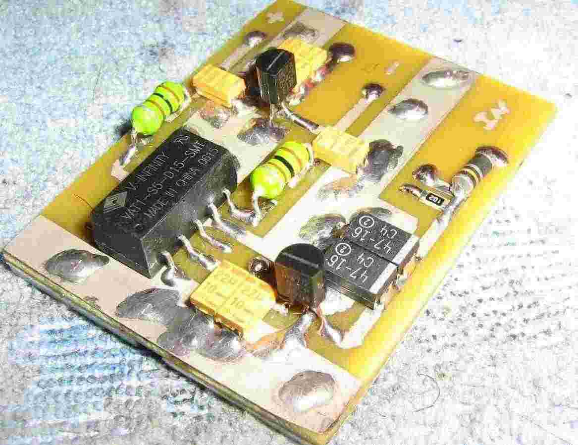
Overview of the circuit's power supply module.
It's based around a V-Infinity VAT1-S5-D15-SMT switching voltage converter. This module takes regulated +5 VDC from a 78L05 and outputs +/- 15 VDC. 100 µH inductors on the output of the converter help to knock down any switching noise.
A 79L05 negative voltage regulator generates the -5 VDC from the -15 VDC rail.
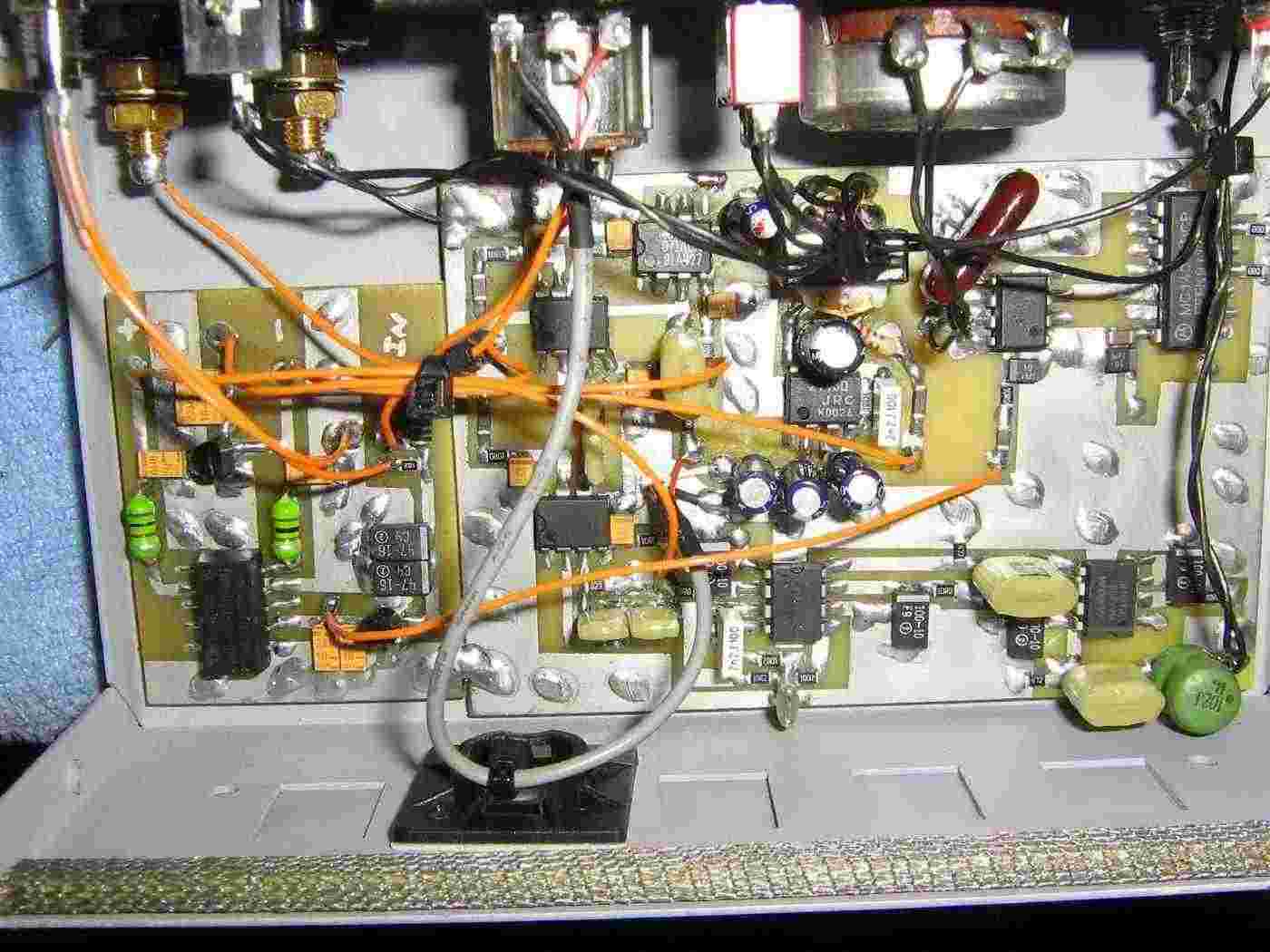
Mounting the circuit board inside an old printer switch case.
The banana jacks on the upper-left are for the +12 VDC power input.
Above the banana jacks are a panel-mounted LED for a power indicator and a 1/8-inch stereo jack for the low-impedance audio (headphone) output.
The middle 10 kohm potentiometer is for the volume. It has an integrated switch to control the main DC power to the circuit.
The larger 2 kohm potentiometer is the clock generator frequency control.
Alternate internal overview.
The audio input/output is via the RCA jacks along the front panel's left-side.
An optional SPDT switch connects the input audio directly to the audio output RCA jack to bypass the filter.