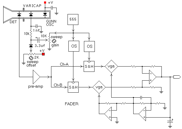
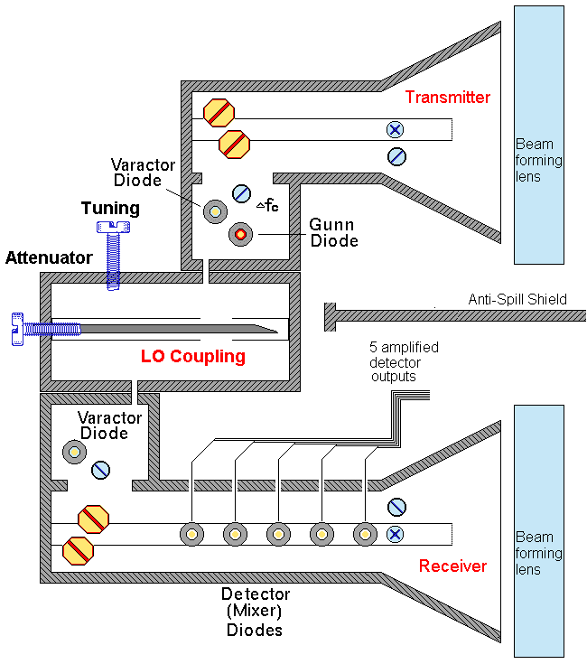
| Suggested Apparatus Configuration
for R & D Testing
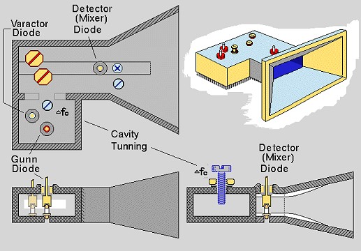
Transmitter:
Emitter type: GUNN or IMPATT (lowest noise device required)
Modulation: CW & Pulsed (for signal processing NOT for Peak Power)
note: IMPATT is typically pulsed; GUNN can be pulsed. (GUNN pulsed
PO = CW PO)
Output: > 50mW
Delta Freq.: VCO (digital VCO ?)
Freq. Range(s): 10 GHz to 45 GHz; in several sub-bands (multiple oscillator
sources will be necessary), e.g., 18-26 GHz, 26-35 GHz, 35-45 GHz
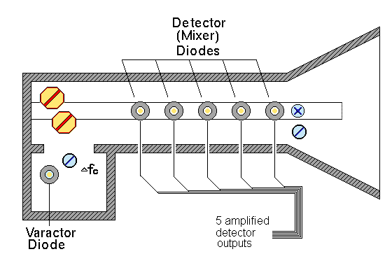
Receiver:
Shottkey microwave Mixer/Detector diodes BW >40 GHz, Waveguide
mounted
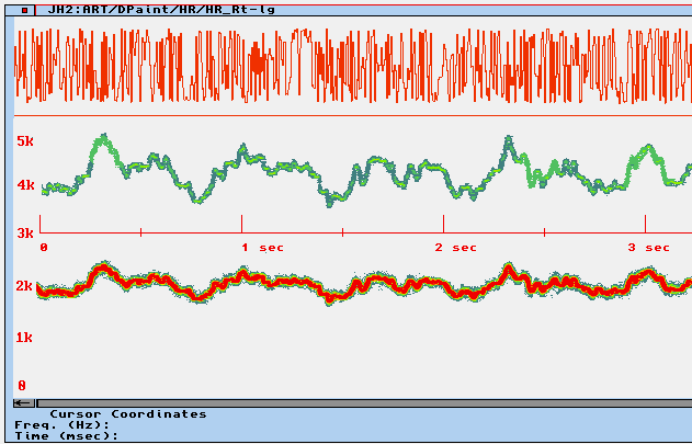
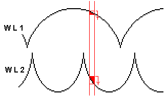
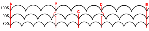
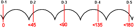
Spatial Diversity Detector Array
Waveguide mounted diode array with spacing between diode
mounts < 45 degrees of WL (for ease of construction, spacing can be
delta + 1 WL, i.e., 0 + 360 = 0, 40 + 360 = 40, 80 + 360 =
80, etc.). see diagram
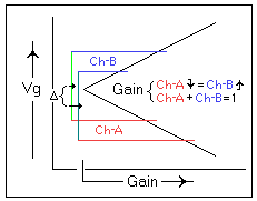
LO injection from Transmitter to receiver is by waveguide coupling with
attenuator.

|