Retyped and cleaned up from an old BBS text file.
Overview
There are many ways to convertly monitor conversations. A microphone or miniature radio transmitter could be planted in the target area. High gain amplifiers with special microphones are used to listen through walls and windows. Parabolic microphones and laser monitoring systems are used to listen from far away. The telephone can be tapped or bugged in a variety of ways. Many times, however, electronic surveillance involves costly equipment that may not be recovered.
There is a cheap and effective way to bug a room. With a piece of wire, an audio amplifier from Radio Shack, and a few cents worth of electronic parts you can modify a telephone to monitor room conversations. This modification, called the "hot-mic" or hookswitch bypass, uses the phone's own microphone and sends the room's audio down the phone line without affecting phone operation. This report will show several ways to perform a hot-mic modification and also how to detect one.
Note: This report is based on the Western Electric 500-type Touch Tone telephone. The modifications will work on other telephones but details such as wire color will be different.
Theory of Operation
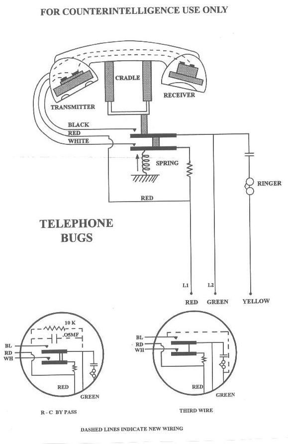
To understand how the hot-mic works, we need to know a little about how the telephone works. The telephone is powered by 48 to 52 Volts DC. When the phone is in use (or off hook) this voltage drops to about 6 Volts. In the four-wire phone cable used at most residences, this voltage and phone audio is carried in the red and green wires, called the RING and TIP, respectively. The ring is negative and the tip is positive. The phone itself roughly consists of the ringer, sidetone coils, hookswitch, earphone and microphone. The microphone is a carbon or electret type that requires some voltage to operate. When the phone is off the hook, 6 Volts is supplied to the microphone.
Here's how the hot-mic works. If a resistor, or a resistor in combination with another component is placed across the hookswitch, enough current will pass to power the phone's microphone but not trip the relay at the central office. Then the microphone transmits room audio down the phone line while it is still on the hook. The audio is recovered with an audio amplifier anywhere along the phone line. When someone uses the modified phone, the hookswitch closes and shorts out the resistor. The phone then operates normally. Figure 1 shows the schematic. The resistor alone is only one hot-mic technique. A more effective job can be done with a resistor and capacitor in parallel or a resistor in series with a semiconductor device called a diac. Also, a 9 Volt battery can be used to hot-mic some phones.
(Figure 1) ![[hook_fig1]](hook_fig1.gif)
Hot-Mic with a Resistor
Using a resistor is the easiest way to hot-mic a phone. With this method, a resistor is placed across the hookswitch, thus activating the phone's microphone. Since most phones contain two (or more) hookswitches, the second hookswitch is shorted out. The value of the resistor must not be too high or too low. If it is too low, too much current will flow and the phone will appear to be off hook, causing a dial tone. If it is too high, the audio will be too weak to recover with the amplifier. A resistance of 10 k (1/4 Watt) across the hookswitch will not cause any of the above problems. A resistance as low as 2.2 k (1/4 Watt) may be used, but problems such as an altered ring or room audio on extension phones may result. After you install the resistor and jumper, check to make sure that all phones ring normally and that the room audio isn't audible on any extensions. It is advantageous to use as low a resistance as possible because the room audio will come through stronger.
The room audio can be recovered anywhere along the phone line with an audio amplifier. Radio Shack sells a nice mini-amplifier for $11.95 (part number 277-1008C). Connect the amplifier to the phone line via a 0.47 uF capacitor to block out the DC voltage as in Figure 2. You should hear room audio although they may be weak. This same setup can be used to eavesdrop on phone conversations too. A word of warning: if you are listening to room audio with the amplifier cranked up all the way and someone picks up the phone, the phone conversation is going to be very loud!
The same amplifier setup is used with the other hot-mic techniques too, such as the ...
(Figure 2) ![[hook_fig2]](hook_fig2.gif)
Hot-Mic with a Resistor and Capacitor
The setup works the same way as the previous one, except a capacitor is placed in parallel with the resistor. See Figure 3 for the schematic. The resistor allows some DC current to pass in order to power the microphone. The audio voltage from the microphone, instead of being attenuated by the resistor, passes easily through the capacitor. This method is better that using just a resistor because the room audio comes through much stronger. Good results may be obtained using a 0.47 uF (250 V / bipolar) capacitor and a 10 k resistor (1/4 Watt). The capacitor must have a rating of at least 200 Volts to handle any ring voltage. As before, check to make sure that the ring is not affected and that room audio can't be heard on extension phones.
(Figure 3) ![[hook_fig3]](hook_fig3.gif)
Hot-Mic with a Resistor and Diac
This method is similar to the others also. A resistor and a diac are placed in series across the hookswitch as in Figure 4. A diac is a bidirectional triggering device similar to a diode which conducts only after a certain breakover voltage is reached. In the hot-mic, the diac conducts when the phone is on hook, but does not conduct when the phone (or any extension) is off hook. This is because the voltage on the phone line drops below the diac's breakover voltage when the phone is off hook. The advantage of this circuit is that no room audio is heard on the extensions because the diac turns the hot-mic off when an extension is picked up. Since we don't have to worry about interference on extensions, we can let more microphone audio leak into the phone lines and get a stronger signal at the amplifier. Use a 2.2 k resistor (1/4 Watt) and a diac such as the Teccor HT-40 (available from Mouser Electronics, part number 519-HT-40). Other diacs will also work. If the phone doesn't ring properly try a higher resistance up to 4.7 k.
This circuit is the best choice for a hot-mic. It offers the most sensitive audio and automatically turns off when any phone is in use.
(Figure 4) ![[hook_fig4]](hook_fig4.gif)
Hot-Mic with a 9 Volt Battery
This circuit uses a different technique to power the microphone. Instead of leaching the power from the phone line, a 9 Volt battery is used. This circuit offers sensitive audio and does not produce a voltage drop on the line. However, it is only useful if there are no extension phones on the line because audio will be present on the extensions. The 9 Volt battery is connected to the microphone via a 1 k (1/4 Watt) resistor to limit current and prolong battery life. One hookswitch is shorted out, and a 0.47 uF capacitor (250 Volt) is placed across the other. In order to turn off the battery when the modified phone is in use, the circuit uses the phone's unused hookswitch contacts. See Figure 5 for schematic. Figure 6 shows a binding post diagram for the Western Electric phone. On a Western Electric 500-type phone the complete hot-mic would consist of the following connections:
- Connect a jumper from L2 to C
- Connect +9 VDC to a 1 k resistor then to F
- Disconnect the GREY wire from L2 and connect it to +9 VDC
- Disconnect the YELLOW wire from L2 and connect it to B
- Connect a 0.47 uF capacitor from L1 to F
This hot-mic can be done with other phones but the hookswitch must contain a switch that is closed when on hook and open when off hook.
(Figure 5) ![[hook_fig5]](hook_fig5.gif) (Figure 6)
(Figure 6) ![[hook_fig6]](hook_fig6.gif)
How to Detect a Hot-Mic
Although a correctly installed hot-mic should not be detectable during normal phone use, there are a few easy ways to check phones for this modification.
- Check the contacts or wires leading to the microphone with voltmeter. There should be NO voltage here when the phone is on hook. If there is, something is definitely wrong.
- Connect an amplifier across the phone line and listen for any suspicious audio. Also check all different combinations of red, green, yellow and black wires for audio. There should be none.
- Check the on hook voltage across the phone lines. If it is less than 48 Volts, a hot-mic may be the cause of the voltage drop. A series phone bug will also cause a drop, but in any case it means trouble.
- Physically inspect the phone. Look for any suspicious wires, resistors, or other components.
- Listen closely to the earphone while the phone is ringing. If there is a faint clicking noise, it means that ringing voltage is leaking into the phone circuitry where it shouldn't be. A hot-mic could be the cause.
Conclusion
This report has shown several ways to make a hot-mic type phone modification. Also several ways of detecting a hot-mic were explained. One should be aware of this method of electronic surveillance. Because of its low cost and simplicity, the hot-mic poses a considerable threat to privacy. Knowledge of it should be available to electronic countermeasures professionals as well as average citizens.
Notes
Hot-Mic How-To from the book: CIA Special Weapons and Equipment: Spy Devices of the Cold War