A laser Doppler vibrometer is based on the principle of the detection of the Doppler shift of coherent laser light that is scattered from a small area of a test object. The object scatters or reflects light from the laser beam, and the Doppler frequency shift is used to measure the component of velocity which lies along the axis of the laser beam.
As the laser light has a very high frequency W (approx. 4.74 x10¹⁴Hz), a direct demodulation of the light is not possible. An optical interferometer is therefore used to mix the scattered light coherently with a reference beam. The photo-detector measures the intensity of the mixed light whose beat frequency is equal to the difference frequency between the reference and the measurement beam. Such an arrangement could be a Michelson interferometer as shown below:
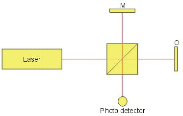
A laser beam is divided by a beam splitter into a measurement beam and a reference beam, which propagates in the arms of the interferometer. The distances the light travels between the beam splitter and each reflector are xR and xM for the reference mirror M and object O, respectively.
The corresponding optical phase of the beams in the interferometer is:
Reference FR = 2kxR
Measurement FM = 2kxM
with k = 2p/l. One usually defines F(t) = FR - FM
The photo-detector measures the time dependant intensity I(t) at the point where the measurement and reference beams interfere.

Where IR and IM are the intensities of the reference and measurement beams, K is a mixing efficiency coefficient and R is the effective reflectivity of the surface.
The phase F = 2pDL/l where DL is the vibrational displacement of the object and l the wavelength of the laser light.
If DL changes continuously, the light intensity I(t) varies in a periodic manner. A phase change F of 2p corresponds to a displacement DL of l/2.
The rate of change of phase F is proportional to the rate of change of position, which is the vibrational velocity v of the surface. This leads to the well-known formula for the Doppler frequency fD:
fD = 2 v/l
Due to the sinusoidal nature of the detector signal, the direction of the vibration is ambiguous. There are two ways to introduce a directional sensitivity:
- solution 1: introduction of an optical frequency shift into one arm of the interferometer to obtain a virtual velocity offset; or
- solution 2: adding polarization components and an additional photo receiver in such a way, that at the interferometer output a second homodyne signal occurs being in quadrature to the primary photodetector output.
The most common form is the first solution. An acousto-optic modulator (Bragg cell) is incorporated into one arm of the interferometer. The Bragg cell is driven at frequencies of 40 MHz or higher and generates a carrier signal at the RF drive (-center) frequency. The movement of the object frequency modulates the carrier signal. The signed object velocity determines sign and amount of frequency deviation with respect to the center frequency fB. This type of interferometer is called a heterodyne interferometer.
With the introduction of a shift frequency fB the intensity at the detector changes to:

The heterodyne solution has significant advantages. As only high-frequency AC signals are transmitted there is no disturbance from hum and noise, introduced by all types of power supplies. Non-linear effects of the photo detector, as well as of all signal pre-processing stages, do not affect the integrity of the Doppler modulation content. The high efficiency of the Bragg cells used by Polytec (>98%) produce less loss than the polarizers needed for solution 2.
The second solution, known as the quadrature homodyne interferometer, can be designed by adding wave retardation plates, a polarizing beamsplitter and a second detector, for example as in the optical system shown below. The interferometer uses a linear polarized laser oriented to give a 45° polarization state. The light in the reference arm passes twice through the eighth wave retardation plate and the light coming back to the beam splitter BS is circularly polarized. This can be described as the vector sum of two orthogonal polarization states. A polarizing beamsplitter PBS placed in front of the detectors 1 and 2 separates the two orthogonal components. The result is a quadrature relationship at the detectors( sine and cosine output). A quadrature homodyne interferometer is much easier to design as simple low-frequency photo detectors and amplifiers can be used. The non-linear behavior of these elements on the other hand causes harmonic distortions of the measurement signal.
To decode signals from homodyne interferometers the baseband signals of both detector chains are fed into a modulator block which generates a modulated RF carrier with the help of an oscillator at the frequency fB

For signal decoding, one can process the phase to produce a displacement output or carry out an FM demodulation to provide the vibrational velocity.
Copyright 2009 Polytec GmbH Technical specifications are subject to change