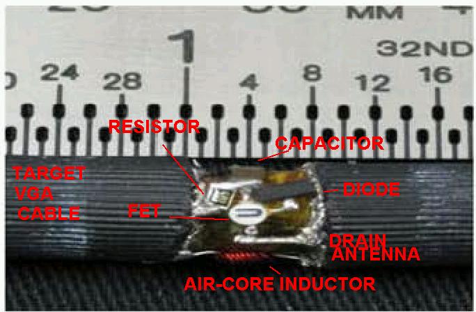
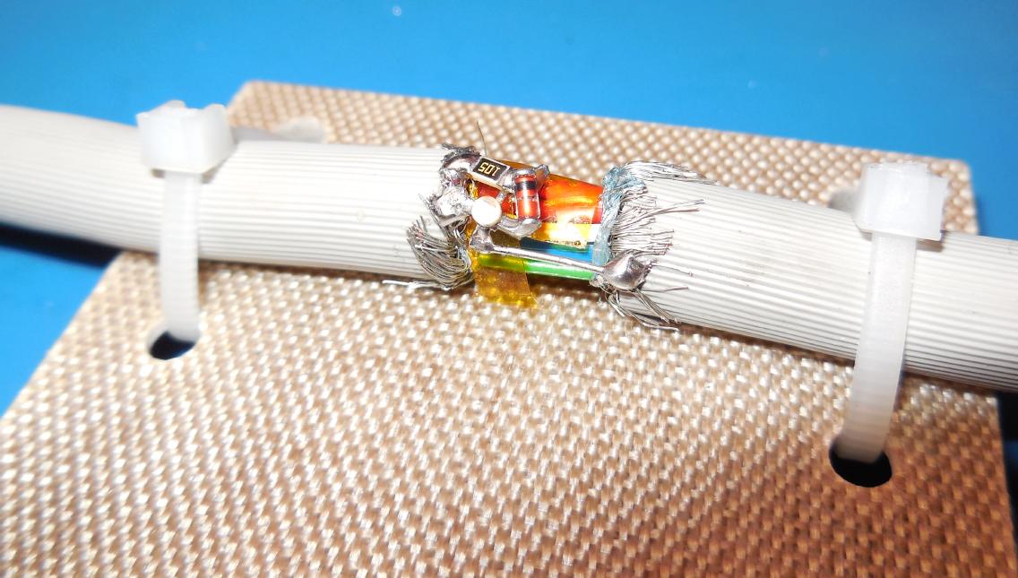
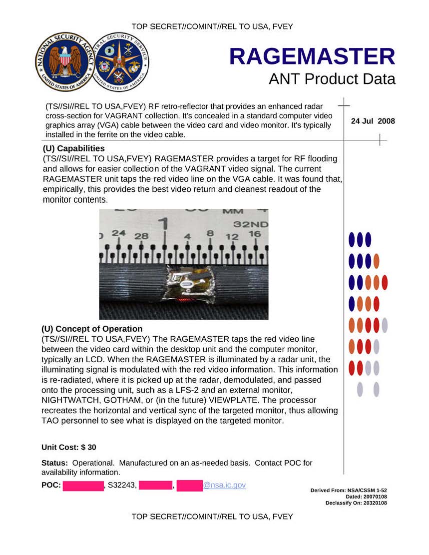
Overview of an actual NSA RAGEMASTER RF retro-reflector installed in a VGA monitor cable. Taken from the NSA's ANT catalog released by Edward Snowden.
The NEC NE33284A FET is the device with the "U" label.
The yellow film is Kapton tape to prevent anything from shorting out.
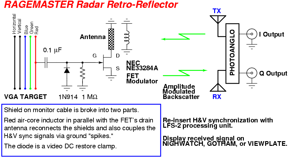
The shield on the VGA cable is broken into two pieces. A small 6-turn air-core inductor (enameled red wire) reconnects the shields and also serves to couples the VGA horizontal & vertical synchronization pulses into the backscattered signal via ground "spikes."
A low-frequency spectrum analyzer on the receive processing unit determines the exact horizontal synchronization frequency. The vertical synchronization frequency can be divided down once the horizontal synchronization frequency is known.
Once the horizontal & vertical sync frequencies are known, they are applied to the host display monitor. The sync frequencies need to be exact (phase-locked, ideally) to the target monitor's original frequencies in order to prevent the picture from "rolling."
The final video signal is processed (amplified and low-pass filtered) just like a standard wideband RF signal and applied to the host display monitor's red video input.
The RAGEMASTER implant is just like the TAWDRYYARD implant, except for the clock oscillator and the addition of the diode.
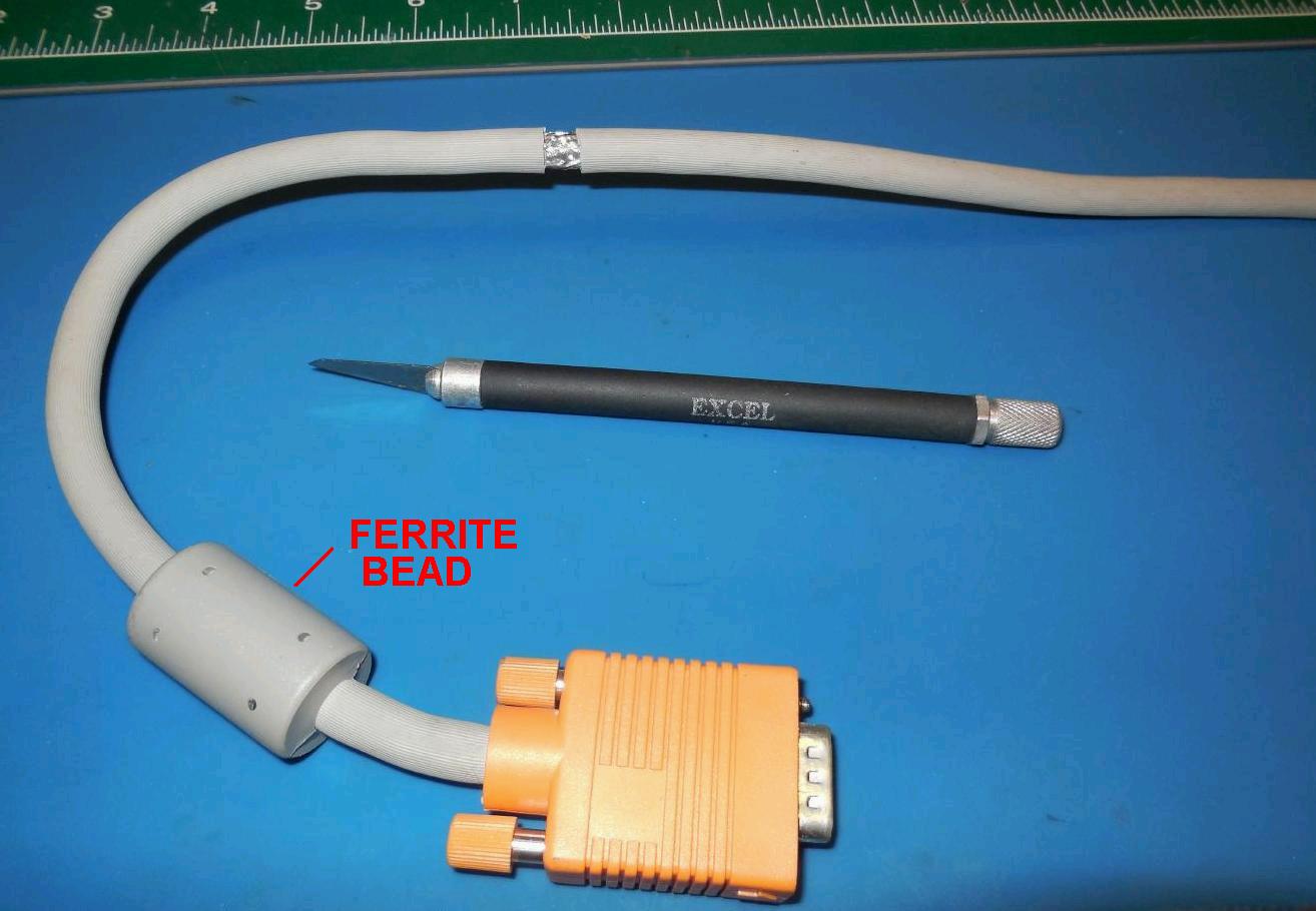
Preparing the VGA video cable for installing of the RAGEMASTER radar retro-reflector.
An approximate 1/4-inch wide piece of the insulation should be carefully removed with a hobby knife.
Real RAGEMASTER radar retro-reflectors are installed under the ferrite bead on the VGA video cable. They are most likely using a fake ferrite bead as the material in a real ferrite beads would attenuate the illumination radar.
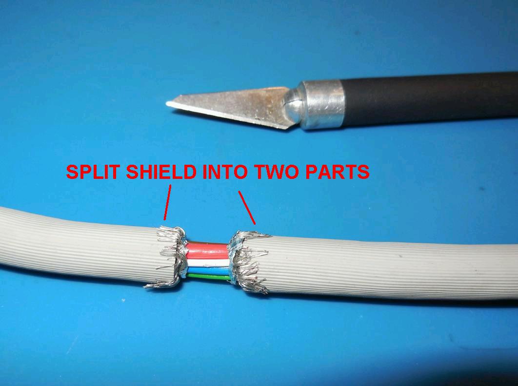
Next you'll want to very carefully split the cable's shield into two separate sections. You should verify this with a multimeter.
This is to break up the ground in order to insert an inductor which will help to couple the target monitor's horizontal and vertical synchronization signals into the reflected (backscattered) signal.
The horizontal & vertical synchronization signals determine the final screen resolution (640x480, 800x600, 1024x768, etc.) and the color of the displayed pixel is determined by the value and intensity of the analog red, green, and blue video signals.
The horizontal & vertical synchronization signals are usually standared +5 volt TTL-level pulses, whereas the red, green, and blue video signals are in a continuous (analog) voltage range from 0 VDC (absolutely dark) to +0.7 VDC (maximum brightness).
Each of these three signals controls an electron gun which illuminates the monitor's phosphor pixels a basic color - red, green, or blue. Any other displayed color is the visual mixture of different levels of brightness of those three primary colors.
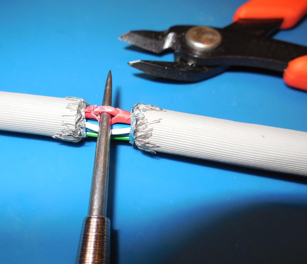
Isolate the red video coaxial cable within the VGA cable bundle.
It's colored red in this particular cable, but that may not always be the case. Double-check with a multimeter to be sure.
Carefully trim away a portion of the outer-shield. Pull out the center conductor and trim away a small portion of its insulation, exposing the center conductor itself. Be sure the center conductor doesn't short against the outer-shield.
In the NSA documents, they state the red video signal provided the best returned signal. I have no idea why this would be the case...
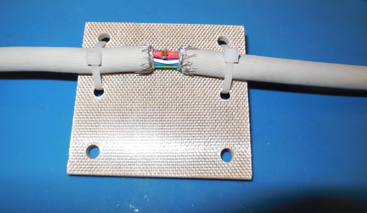
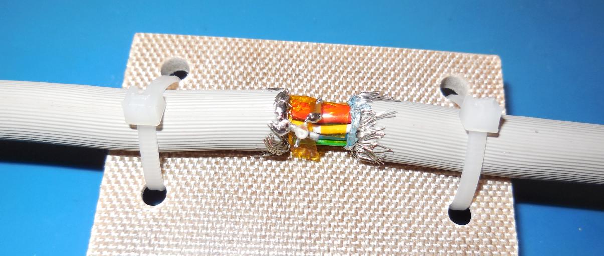
Adding the RAGEMASTER radar retro-reflector components to the target VGA video cable.
It helps to secure (zip-tie) the cable to a small plate, like shown above, to prevent the cable from flopping around when you work on it.
One end of a surface-mount 0.1 µF capacitor is soldered to the red video center conductor.
A larger value video coupling capacitor would probably work better, but this application needs to maintain a high-impedance tap to prevent any loading on the low-impedance (75 ohm) target video signal which could reveal your implant.
Next, a few pieces of Kapton tape were wrapped around the wire bundle to secure and prevent anything from shorting out.
A Fujitsu FHX35LG FET is used for this retro-reflector instead of the NEC NE33284A shown in the NSA's document.
The gate of the FET is soldered to the other end of the 0.1 µF capacitor and the left source pin is soldered to the left shield (ground) on the VGA video cable.
Next, a 1 megaohm gate bias resistor is added from the Fujitsu FHX35LG gate to the left shield (ground).
Next, a 1N4148 or similar diode is added from the Fujitsu FHX35LG gate (cathode) to the right source lead, which is at ground potential.
This diode acts like a DC clamp for the video signal.
Analog video signals determine their intensity by their absolute voltages, 0-700 millivolts usually.
When you AC couple the video signal, required to avoid loading the target signal, you loose the "reference" to which the video signal was generated.
This can be recreated by adding a simple diode clamp to readjust the video signal so that it regains its original absolute voltage at known portions within the video signal.
Next, a small piece of wire is added from the the Fujitsu FHX35LG drain to the right shield (ground).
Utilizing the two different grounds generates a differential voltage within the ground system to futher help couple the horizontal and vertical synchronization signals into the backscattered signal.
Here are some example VGA signal timing specifications:
| Video Mode |
Pixel Clock
(MHz) |
Horizontal Sync
(kHz / Polarity) |
Horizontal (in Pixels) |
Vertical (in Lines) |
Active
Video |
Front
Porch |
Sync
Pulse |
Back
Porch |
Active
Video |
Front
Porch |
Sync
Pulse |
Back
Porch |
| 640x480, 60 Hz |
25.175 |
31.469 / Neg |
640 | 16 | 96 | 48 |
480 | 11 | 2 | 31 |
| 640x480, 75 Hz |
31.500 |
37.500 / Neg |
640 | 16 | 96 | 48 |
480 | 11 | 2 | 32 |
| 640x480, 85 Hz |
36.000 |
43.269 / Neg |
640 | 32 | 48 | 112 |
480 | 1 | 3 | 25 |
| 800x600, 75 Hz |
49.500 |
46.875 / Pos |
800 | 16 | 80 | 160 |
600 | 1 | 2 | 21 |
| 800x600, 85 Hz |
56.250 |
53.674 / Pos |
800 | 32 | 64 | 152 |
600 | 1 | 3 | 27 |
| 1024x768, 75 Hz |
78.750 |
60.023 / Pos |
1024 | 16 | 96 | 176 |
768 | 1 | 3 | 28 |
| 1024x768, 85 Hz |
94.500 |
68.677 / Pos |
1024 | 48 | 96 | 208 |
768 | 1 | 3 | 36 |
On the DB15 VGA connector, the relevant pins are:
DB15 Pin       Description
1              Red Video
6              Red Video Ground
10             Sync Ground
13             Horizontal Sync
14             Vertical Sync
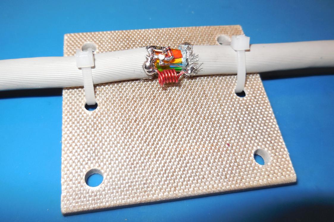
Next, a small 6-turn enameled air-core inductor is added to reconnect the separate (left & right) cable shields.
This is done to create an impedance "bump" within the ground system to help couple the sync signals into the backscattered signal.
Ideally, the air-core inductor should be physically smaller, with 30-gauge wire or so. The exact inductance isn't too critical.
Do be sure the red video signal ground and the cable shield are tied together. Some of the cheaper VGA cables don't have the shield or it's not connected to anything!
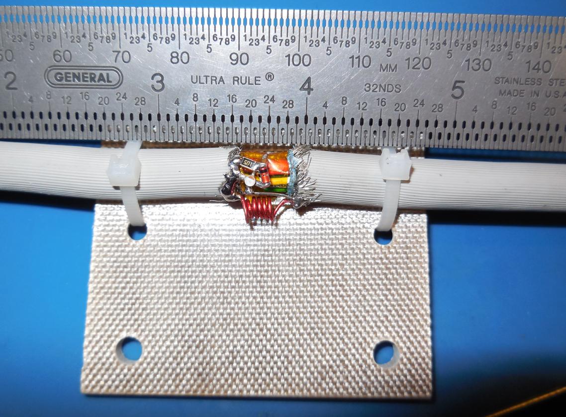
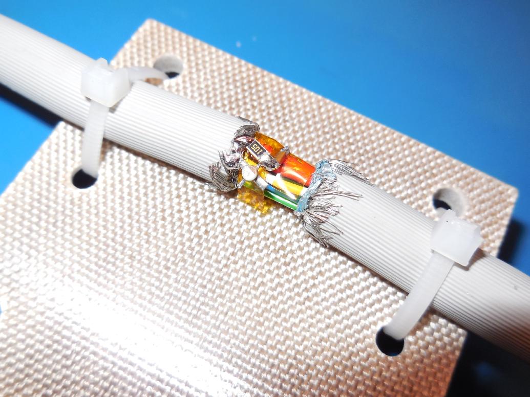
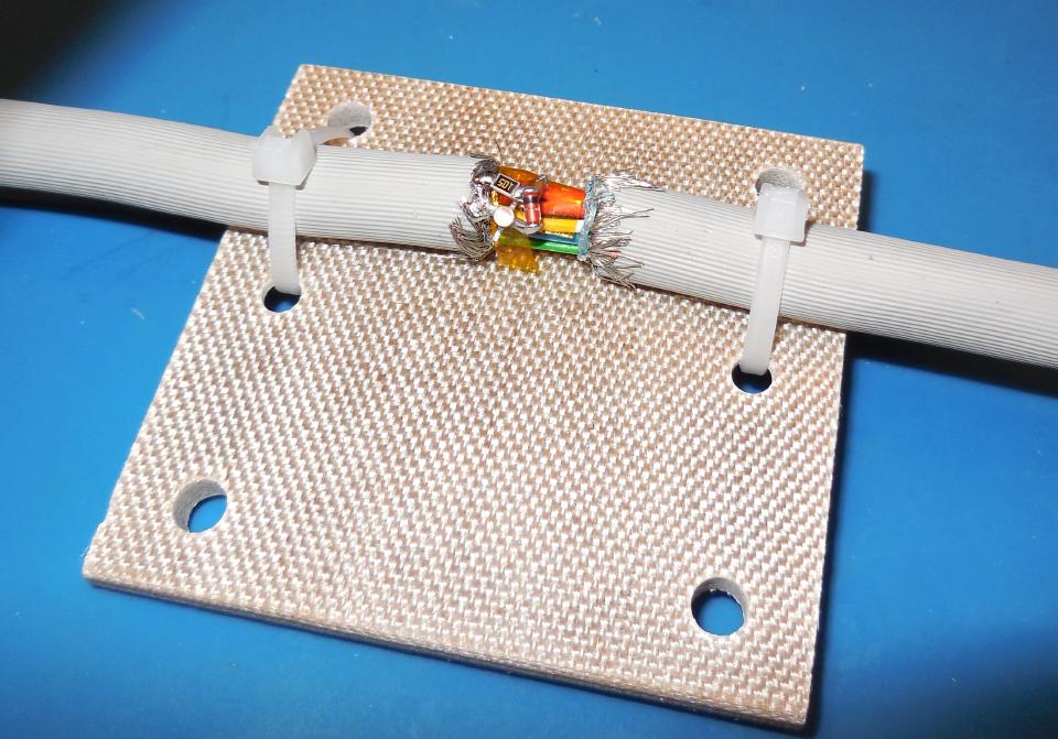
Completed experimental RAGEMASTER radar retro-reflector installed in a VGA monitor cable.
Since these radar retro-reflector don't contain a clock, a TAWDRYYARD beacon is often planted to help point the illumination radar (CTX4000/PHOTOANGLO) in the right direction.
To view the received (backscattered) video signal, you'd need to take the I or Q output from the CTX4000/PHOTOANGLO illumination radar unit and run that through some IF amplification (40 dB or more, probably) and low-pass filtering/post-processing.
You'd then inject this amplified signal into the red video line on your host VGA monitor which is supplying the horizontal & vertical synchronization signals.
You can use a low-frequency spectrum analyzer to monitor the received signal to determine the exact horizontal synchronization frequency your host VGA monitor should be opeating at. The proper vertical synchronization frequency can then "divided down" once you find that frequency.
If the horizontal & vertical synchronization frequencies are not the same as the target VGA monitor, the display will "roll" on your host monitor and you won't be able to see anything!
An external tunable sync generator would need to be constructed to tweak the final synchronization frequencies. This is most likely what the NSA's LFS-2 device does.
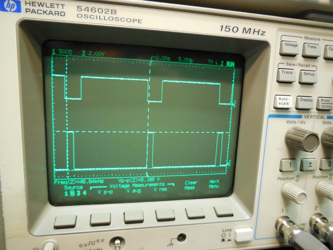
Oscilloscope view of an "all red" 800 x 600 pixel resolution VGA signal (top trace) which will be used for testing.
It has a horizontal sync frequency (bottom trace) of around 46.84 kHz and a vertical sync frequency (not shown) of 75 Hz.
Both the horizontal & vertical sync frequencies are considered "postive" triggered. Some resolutions use negative-edge triggering.
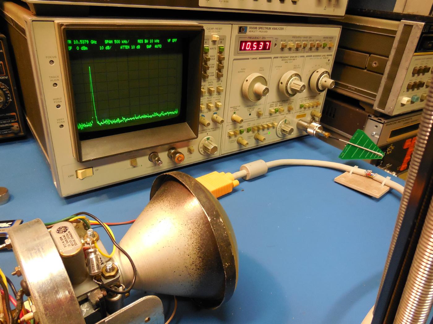
Backscatter video modulation test setup, unmodulated carrier.
On the left, is the unmodulated CW illumination radar, which is a Decatur MV715 RangeMaster operating in the X-band (approximately 10.5 GHz).
The HP8569B spectrum analyzer is showing the unmodulated RF carrier and is centered at 10.537 GHz.
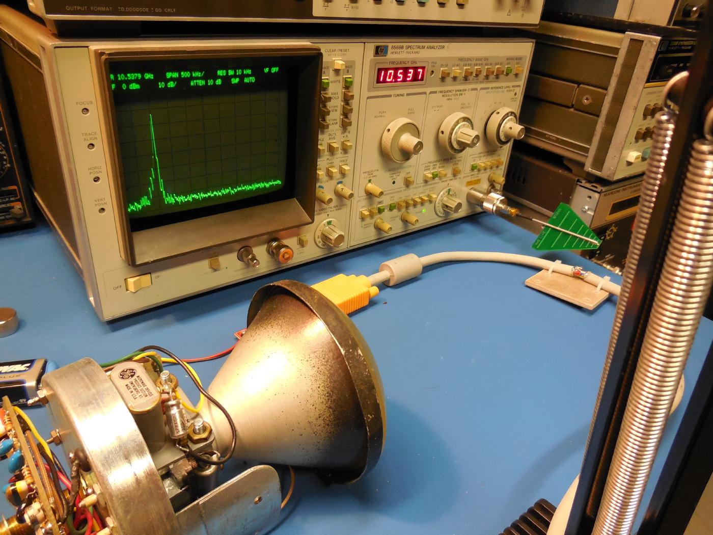
Backscatter video modulation test setup.
The test RAGEMASTER radar retro-reflector installed in a VGA cable is setup inbetween the Decatur MV715 RangeMaster (left) and the spectrum analyzer's RF input (right).
The FHX35LG FET is being (gate) modulated with the red video line of the VGA test signal.
The amplitude modulated backscatter video signal is being received and displayed on the spectrum analyzer.
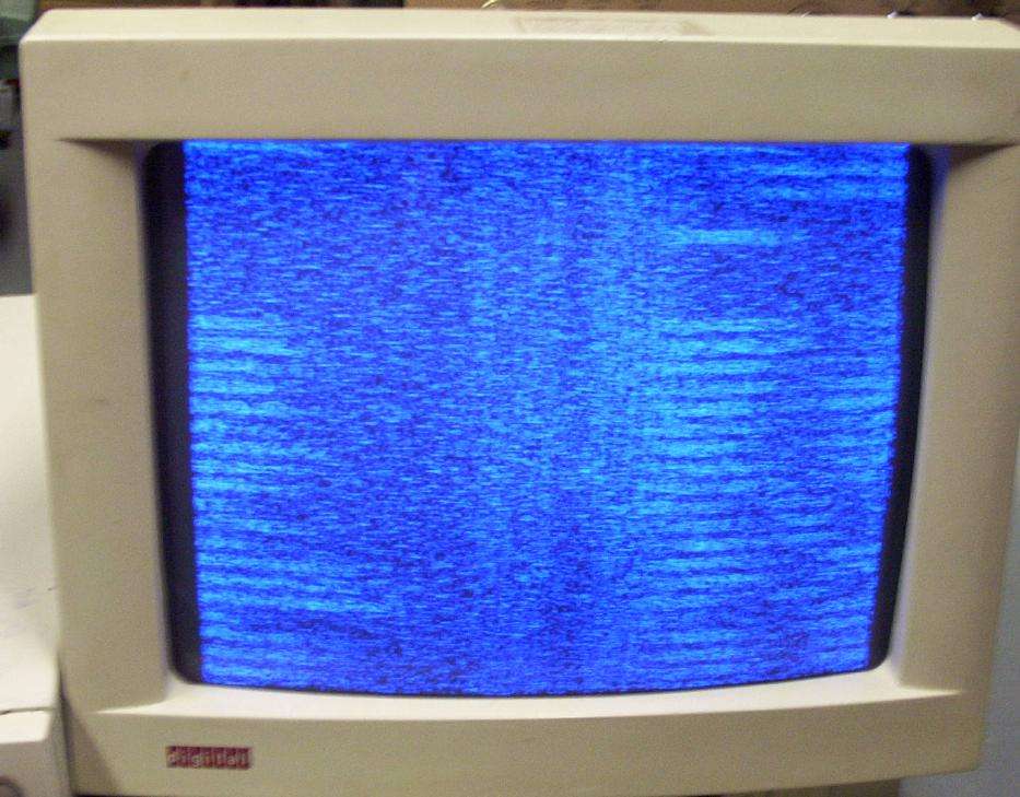
If you were to AM demodulate the backscattered signal, and apply it to the video input of a monitor operating at the same horizontal & vertical sync frequencies as the target monitor, you'd be able to see what's on the screen - or that's the idea at least...
The target monitor's sync frequencies are also modulated within the backscattered video signal. The horizontal sync frequencies will appear as a series of "spikes" within the video signal on the spectrum analyzer.
You can "hear" the vertical sync frequencies (60/75/85 Hz or so) via the illumination radar's output with a standard audio amplifier and headphones.
GBPPR Vision #28: Overview of the NSA's RAGEMASTER Radar Retro-Reflector (YouTube)