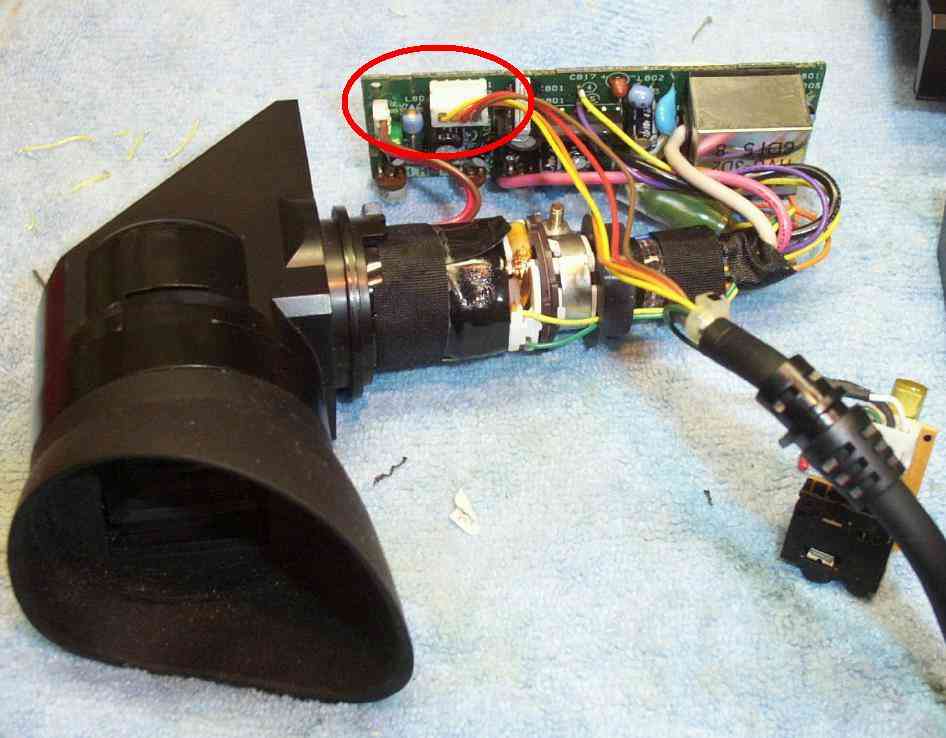
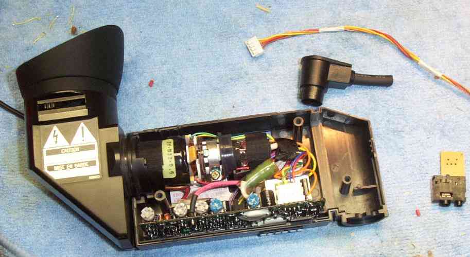
Monitor eyepiece from an old RCA CMR300 VHS camcorder. It's actually a miniature CRT feeding a mirror set at an angle. The original video input comes in from the cable on the right. The connector with the red circle is the one we are interested in. Viewing the wires, from left-to-right, the YELLOW wire is for the RECORD LED (and can be cut off), the ORANGE wire is +9 VDC, with a current draw of around 120 mA, the RED wire is the VIDEO INPUT, and the BROWN wire is a common GROUND.
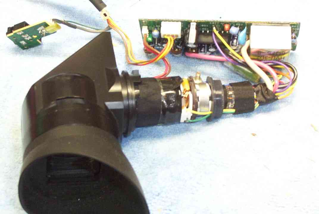
Alternate wire bundle view. The shielded wire (on the left) going into the 1/8-inch jack is for the microphone.
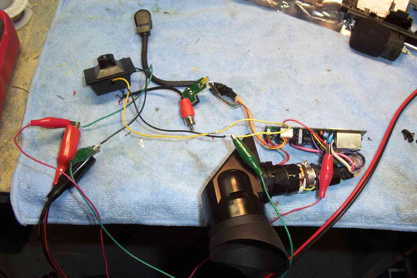
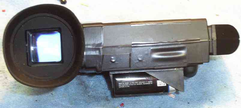
Test setup. A small CMOS camera (the black, square thing) is connected directly to the video input line. (YELLOW wire from the camera, BLACK wire is ground). +9 VDC is feeding both the camera and the eyepiece (RED alligator clips).
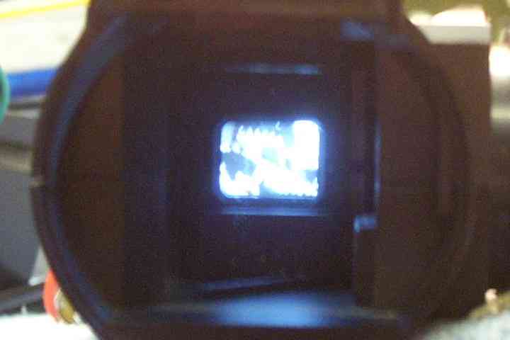
Eyepiece showing the video output from the camera. Add a few high-power infrared LEDs, and you'll have a cheap night vision viewer.
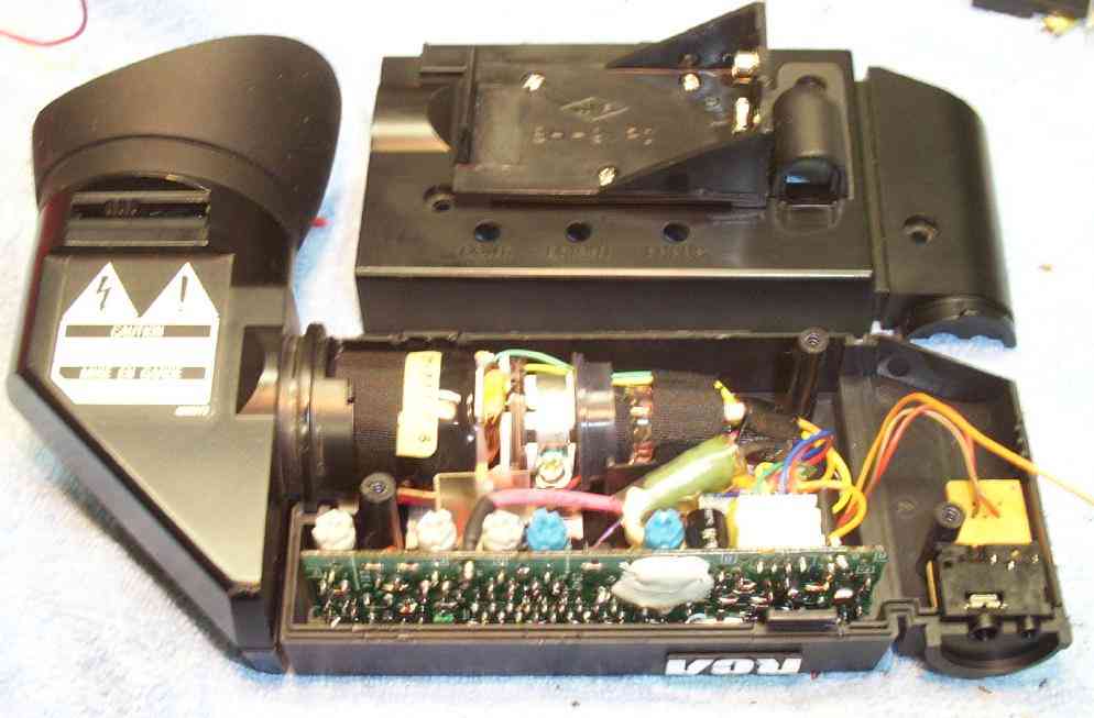
Putting everything back together. The original 1/8-inch jack for the microphone will become the new video input jack. Unsolder all the wires from the little support board, and "pin-out" the 1/8-inch jack's connections using a continuity tester. Then, prepare the wiring bundle for installation (top).
Installation of the new 1/8-inch video input jack. The RED wire goes to the corresponding TIP connection and the BROWN wire goes to the SHIELD and a common ground. The top cover is prepared with the installation of the 9-volt battery holder. The ORANGE wire will go to the battery holder's POSITIVE (+) terminal. The battery holder's NEGATIVE (-) terminal will be connected to common ground with a jumper wire. There is no need to wire in a switch, but it could be useful.
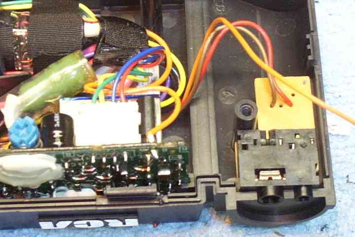
Close up picture of the microphone input jack converted into a video input jack.
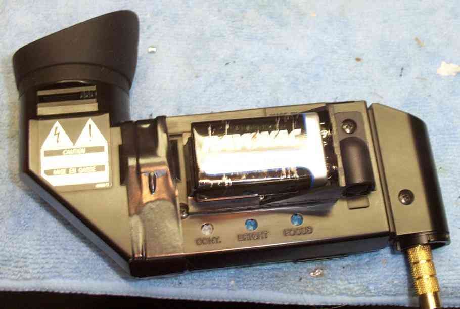
Everything is put back together. A 1/8-inch mono plug to phono jack adapter may be needed, depending on your camera's output connection. Package the GBPPR Video Camera Viewer with a wide selection of different adapters and extra 9-volt batteries. Note the CONTRAST, BRIGHTNESS, and FOCUS adjustment potentiometers. Your eyepiece will most likely require readjustment. You'll have to do this via trial-and-error.
And it works! A few turns of electrical tape keep the eyepiece's viewer hood from rotating or breaking off.
The eyepiece's 120 mA current draw is about twice what a standard, alkaline 9-volt battery is capable of sourcing, so it doesn't last very long. About 15 minutes of continuous operation can be expected.