Mixers are used to convert a signal from one frequency to another. This is done by combining the original RF signal with a local oscillator (LO) signal in a non-linear device such as a Schottky-barrier diode.
The output spectrum includes:
The desired output frequency, commonly called the intermediate frequency (IF), can be either the lower (LO-RF) or upper (LO+RF) sideband. When a mixer is used as a down converter, the lower sideband is the sideband of interest.
A microwave balanced mixer makes use of the 3 dB hybrid to divide and recombine the RF and LO inputs to two mixing diodes. The 3 dB hybrid can be either the 90° or 180° type. Each has certain advantages which will be covered later. The critical requirement is that the LO and RF signals be distributed uniformly (balanced) to each mixer diode.

Figure 1 is a typical balanced mixer block diagram. The mixer diodes are reversed relative to each other; the desired frequency (IF) components of each diode are then in-phase while the DC outputs are positive and negative respectively.
The two diode outputs are summed in a tee where the DC terms cancel and only the desired IF component exists at the IF port.
Other types of mixers exist, including the double-balanced mixer, and the Ortho-Quad® (quadrature fed dual) mixer. The relative advantages and disadvantages of each of the four types are summarized in Table 1.
Table 1. Mixer Comparison
|
Mixer Type |
VSWR 1 |
Conversion Loss 2 |
LO/RF Isolation 3 |
Harmonic Suppression 4 |
Dynamic Range |
IF Bandwidth |
|
90° Hybrid |
good |
lowest |
poor |
poor-fair |
high |
wide |
|
180° Hybrid |
poor |
low |
good |
good |
high |
wide |
|
Double-Balanced |
poor |
low |
Very good -excellent |
very good |
high |
extremely wide |
|
Ortho Quad |
good |
low |
very good |
fair |
high |
wide |
NOTES:
Used in various circuits, mixers can act as modulators, phase detectors, and frequency discriminators.
The phase discriminators can serve as a signal processing network for systems designed to monitor bearing, polarization, and frequency of AM or FM radiated signals.
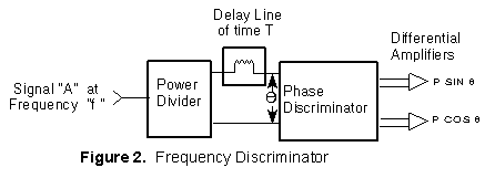
A frequency discriminator uses a phase discriminator and adds a power divider and delay line at the RF input as shown in Figure 2.
The unknown RF signal "A" is divided between a
reference and delay path. The differential delay ( T ) creates a phase difference
( ) between the two signals which is a linear function of
frequency ( f ) and is given by = 2
) between the two signals which is a linear function of
frequency ( f ) and is given by = 2 f T.
f T.
When the two output signals are fed to the horizontal and vertical input of an oscilloscope, the resultant display angle will be a direct function of frequency.