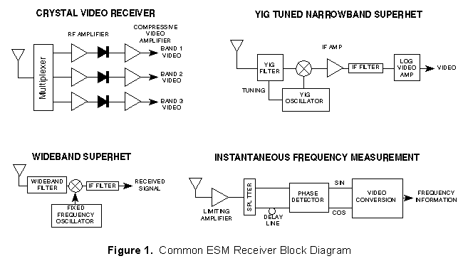
Besides the considerations of noise and noise figure, the capabilities of receivers are highly dependant on the type of receiver design. Most receiver designs are trade-offs of several conflicting requirements. This is especially true of the Electronic Support Measures (ESM) receivers used in Electronic Warfare. This section consists of a figure and tables that provide a brief comparison of various common ESM receiver types. Figure 1 shows block diagrams of four common ESM receivers.
Table 1 is a comparison of major features of receivers. Table 2 shows the receiver types best suited for various types of signals and Tables 3 and 4 compare several direction of arrival (DOA) and emitter location techniques. Table 5 shows qualitative and quantitative comparisons of receiver characteristics.
|
|
|
|
|
| Wideband crystal video |
Simple, inexpensive, instantaneous, High POI in frequency range |
No frequency resolution Poor sensitivity and Poor simultaneous signal performance |
RWR |
| Turned RF Crystal Video |
Simple, Frequency measurement Higher sensitivity than wideband |
Slow response time Poor POI |
Option in RWR, Frequency measurement in hybrid |
| IFM |
Relatively simple Frequency resolution Instantaneous, high POI |
Cannot sort simultaneous signals Relatively poor sensitivity |
Shipboard ESM, Jammer power management, SIGINT equipment |
| Narrow-band scanning Superhet |
High sensitivity Good frequency resolution Simultaneous signals don't interfere |
Slow response time Poor POI Poor against frequency agility |
SIGINT equipment Air and ship ESM Analysis part of hybrid |
| Wide-band Superhet | Better response time and POI |
Spurious signals generated Poorer sensitivity |
Shipboard ESM Tactical air warning |
| Channelized | Wide bandwidth, Near instantaneous, Moderate frequency resolution | High complexity, cost; Lower reliability; limited sensitivity |
SIGINT equipment Jammer power management |
| Microscan |
Near instantaneous, Good resolution and dynamic range, Good simultaneous signal capability |
High complexity, Limited bandwidth No pulse modulation information Critical alignment |
SIGINT equipment Applications for fine freq analysis over wide range |
| Acousto-optic |
Near instantaneous, Good resolution, Good simultaneous signal capability Good POI |
High complexity; new technology | . |
|
|
|
|||||||
|
|
|
|
|
|
|
|
|
|
| CW | Special design for CW | Special design for CW | Yes, but interferes with pulsed reception | Yes | Yes | Yes | Yes | Yes |
| Pulsed | Yes | Yes | Yes | Yes | Yes | Yes | Yes | Yes |
| Multiple Frequency | No | No | No | Yes, but won't recognize as same source | No | Yes | Yes | Yes |
| Frequency Agile | Yes, doesn't measure frequency | No | Yes | No | Yes (within passband) | Yes | Yes | No/Yes, depending on readout time |
| PRI Agile | Yes | Yes | Yes | No/Yes, depending on scan rate | Yes | Yes | No/Yes, imprecision in TOA | No/Yes, depending on readout time |
| Chirped | Yes, within acceptance BW | No | Yes | No/Yes, depending on BW | Yes | Yes (reduced sensitivity) | No/Yes, depending on scan rate | Yes (reduced sensitivity) |
| Spread Spectrum | Yes, within acceptance BW | No | Yes | No | No/Yes, depending on BW | Yes (reduced sensitivity) | Yes (reduced sensitivity) | Yes (reduced sensitivity) |
| . | Amplitude Comparison | Phase Interferometer |
| Sensor Configuration | Typically 4 to 6 Equal Spaced Antenna Elements for 360° Coverage | 2 or more RHC or LHC Spirals in Fixed Array |
| DF Accuracy |
(Gaussian Antenna Shape) |
|
| DF Accuracy Improvement | Decrease Antenna BW; Decrease Amplitude Mistrack; Increase Squint Angle | Increase Spacing of Outer Antennas; Decrease Phase Mistrack |
| Typical DF Accuracy | 3° to 10° rms | 0.1° to 3° rms |
| Sensitivity to Multipath/Reflections | High Sensitivity; Mistrack of Several dB Can Cause Large DF Errors | Relatively Insensitive; Interferometer Can be Made to Tolerate Large Phase Errors |
| Platform Constraints | Locate in Reflection Free Area | Reflection Free Area; Real Estate for Array; Prefers Flat Radome |
| Applicable Receivers | Crystal Video; Channelizer; Acousto-Optic; Compressive; Superheterodyne | Superheterodyne |
|
S = Squint Angle in degrees |
||
| Measurement Technique | Advantages | Disadvantages |
| Triangulation | Single Aircraft |
Non-instantaneous location Inadequate accuracy for remote targeting Not forward looking |
| Azimuth/elevation |
Single Aircraft Instantaneous location possible |
Accuracy degrades rapidly at low altitude Function of range |
| Time Difference of Arrival (Pulsed signals) |
Very high precision Can support weapon delivery position requirements Very rapid, can handle short on-time threat |
Very complex, diverse systems required, at least 3 aircraft High quality receivers, DME (3 sites) very wideband data link Very high performance control processor; requires very high reliability subsystems |
| Feature | Receiver Type | |||||||
| Wide-Band Crystal Video | TRF Crystal Video | IFM | Narrow-Band Superhet | Wide-Band Superhet | Channelized | Microscan | Acousto-optic | |
| Instantaneous Analysis Bandwidth | Very wide | Narrow | Very wide | Narrow | Moderate | Wide | Wide | Moderate |
| Frequency Resolution | Very poor | Fair | Good | Very good | Poor | Fair | Good | Good |
| Sensitivity | Poor (No preamp) Fair (preamp) | Fair/ good | Poor (No preamp) Fair (preamp) | Very good | Fair | Fair/ good | Very good | Good |
| Dynamic Range | Fair | Fair/ good | Good | Very good | Fair | Good | Fair | Poor |
| Speed of Acquisition | Very Fast | Slow | Very Fast | Slow | Fast | Very Fast | Very Fast | Fast |
| Short pulse Width Capability | Good | Good | Good | Good | Very good | Good | Fair | Fair |
| Retention of Signal Character-istics | Fair | Fair | Poor | Good | Fair/ good | Good | Poor |
Fair/ good |
| Applicability to Exotic Signals | Poor/ fair | Poor | Good | Poor | Fair/ good | Good | Fair/ good | Fair/ good |
| High signal Density Performance | Poor (high false alarm rate from background) | Fair/ good | Good | Poor | Fair (depending on BW) | Fair/good, depending on architecture & processing | Good | Poor |
| Simultaneous Signal Capability | Poor | Fair/ good | Poor | Good | Fair (depending on BW) | Good | Good | Good |
| Processing Complexity | Moderate depending on application | Moderate depending on application | Moderate | Moderate | Moderate | Low-high depending on architecture | Complex | Simple signal processing complex data processing |
| Immunity to Jamming | Poor | Fair | Poor/ Fair | Good | Poor/ Fair | Good | Good | Good |
| Power Requirements | Low | Low/ Moderate | Moderate | Moderate | Moderate | High | Moderate | Moderate/ High |
| RF Range (GHz) | Multi-octave (0.5-40) | 0.15-18 separate | >0.5 to 40 | <0.01 to 40 | 0.5 to 18 | 0.5 to 60 | <0.5 to 8 | 0.5-4 (0.5-18 channelized and down conversion) |
| Max Instantaneous Analysis Bandwidth | Multi-octave (to 17.5 GHz) | As high as desired with equivalent reduction in resolution | Multi- octave (1 octave per unit) | 50 MHz | 500 MHz | ~2 GHz without degradation, 17.5 GHz with degradation | 0.5 to 2 depending on PW limitation | 1 GHz |
| Frequency Accuracy | Measurement accuracy no better than analysis BW | Measurement accuracy no better than analysis BW | 5-10 MHz | 0.5% to 1% | 0.5 to 3 MHz | +/- 1 MHz | 10 KHz | +/- 1 MHz |
| Pulse Width Range | CW to 50 ns | CW to 50 ns | CW to ~20 ns (depending on resolution) | CW to 100 ns with 20 MHz resolution | CW to 4 ns with 500 MHz resolution | CW to 30 ns depending on resolution | CW to 250 ns | CW to 0.5 µs |
| Frequency Resolution | ~400 MHz (no better than BW) | 25 MHz | 1 MHz | <0.1 MHz | 100-500 MHz | 10-125 MHz (less with freq vernier) | 1 MHz | 0.5 to 1 MHz |
| Sensitivity (dBm) | -40 to -50 (no preamp) -80 (with preamp) | Better than -80 with preamp | -40 (no preamp) -75 (preamp) 4 GHz BW | -90, 1 MHz BW | -80, 500 MHz BW | -70, 10-50 MHz BW | -90, 5-10 MHz BW | -70 to -80 |
| Maximum Dynamic Range (dB) | 70 | 70-80 | 80 (w/preamp) 100+ (saturated) | 90 | 60 | 50-80 | 40-60 | 25-35 |
| Tuning Time | - | 50 ms | - | 1.0 s (1 octave) | 0.12 s (200 MHz band) | - | 0.3 µs LO scan time | 0.5 ms (integration time) |
| Signal ID Time | 100 ns | 50 ms | 2-10 ms | ~0.1 s | - | 2.10ms | ~1 µs | - |
| Minimum Weight (lb) | 20 (with processor) | 30 | <20 (octave unit) 65-75 (full coverage) | 60-75 | 35 (tuner only) | 1309-200 for 0.5 to 18 GHz coverage | 25 | 29-55 |
| Size / Minimum Volume (cu in) | Small 300 (w/processor) | Small 375 | Sm/Moderate 600-1000 ~100 miniaturized | Moderate 1500-3000 | Moderate Several thousand | Large 4000-8000 (0.5-18 GHz coverage | Moderate 1200-2000 | Small 800-1900 |
| Minimum Power (W) | 100 (with processor) <10 without processor | 60 (without processor) | ~50 (octave unit) | 150 | 150 (tuner only) | 350 to 1200 for 0.5 to 18 GHz coverage | 70-80 | 200 |
| Cost | Low | Low/ Moderate | Moderate | Moderate/ High | Moderate/ High | High | Moderate/ High | Low/ Moderate |