0.55 µF / 2,300 VAC microwave oven voltage-doubling capacitor.
First, we'll show a little tip to salvage 10 Megaohm resistors capable of operating at high-voltages (2+ kilovolts).
Every high-voltage microwave oven capacitor should have an internal 10 Megaohm resistor across the leads to help drain the high-voltage charge when the AC power is off. We can salvage these resistors for use in high-voltage divider networks or for drain resistors in your own power supply circuits.

Start by cutting the bottom off the capacitor with a hacksaw.
The capacitor will leak its dielectric fluid, so be prepared. The fluid should be non-toxic, but be careful.
Use a needle-nose pliers to pull out the wrapped foil package which makes up the actual capacitor. It will be attached by its two leads, but should easily pull out with just a quick tug.
You'll want to then begin peeling back the outside case of the capacitor. This should expose the resistor across the capacitor's two terminals.
The resistor will be mounted on a ceramic substrate, so be careful removing it so it doesn't crack.
You can clip or unsolder the leads, as necessary.
Salvaging the original 4 kV power supply circuit.
Remove the internal components, leaving the AC input socket, fuse, neon lamp, AC line filter, and power switch.
We'll be adding a separate fuse to protect the output of the Variac.
The BNC connector will be an optional "High-Voltage Test Point" for monitoring the power supply's DC output via a "divide-by-100" resistive network.
It think the BNC connector should have been an isolated version to help keep a single-point ground.
Mount the Variac to the front-panel of the case.
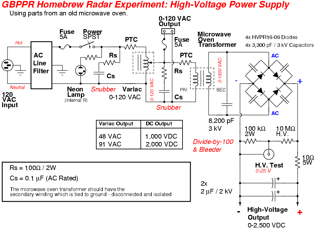
The little green blob on the Variac's AC input is a surge-suppression PTC resistor from an old computer/monitor switching power supply. This is used to limit the input current rush on power up. The blue series capacitor-resistor network form a snubber to clamp any voltage spikes from the Variac's primary winding on power up or down.
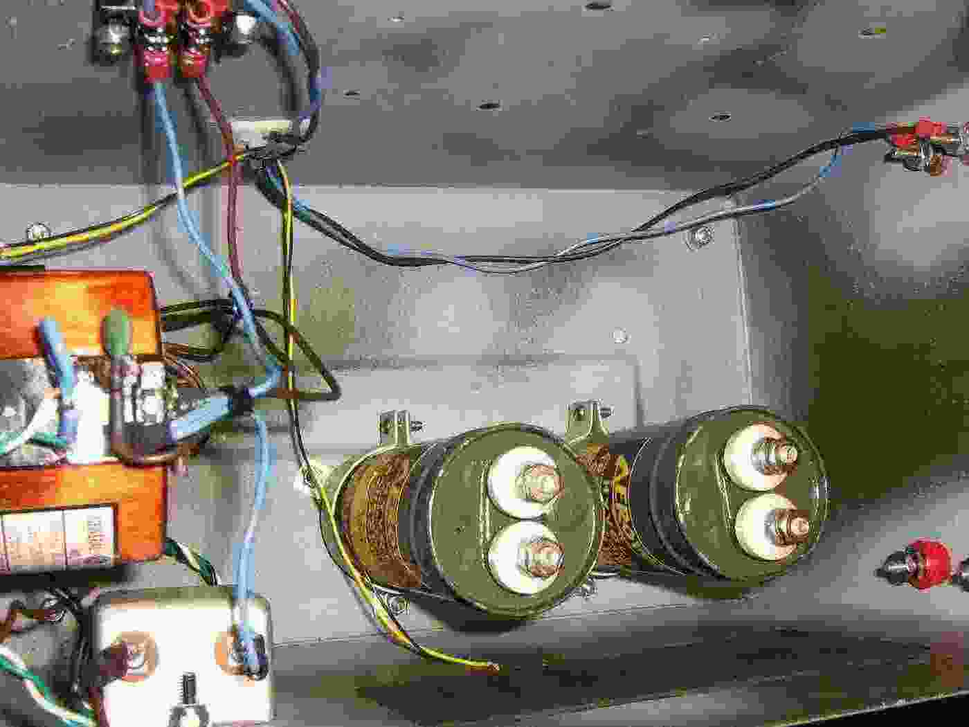
Install the high-voltage filtering capacitors.
Shown here are two Aerovox 2 µF, 2,000 WVDC capacitors I found at a hamfest. Several paralleled microwave oven capacitors will also work, but try to keep them all the same value.
Be sure to take proper high-voltage contruction and mounting considerations into play when working around these capacitors.
The AC output of the Variac connects to the terminal block shown on the top of the picture.
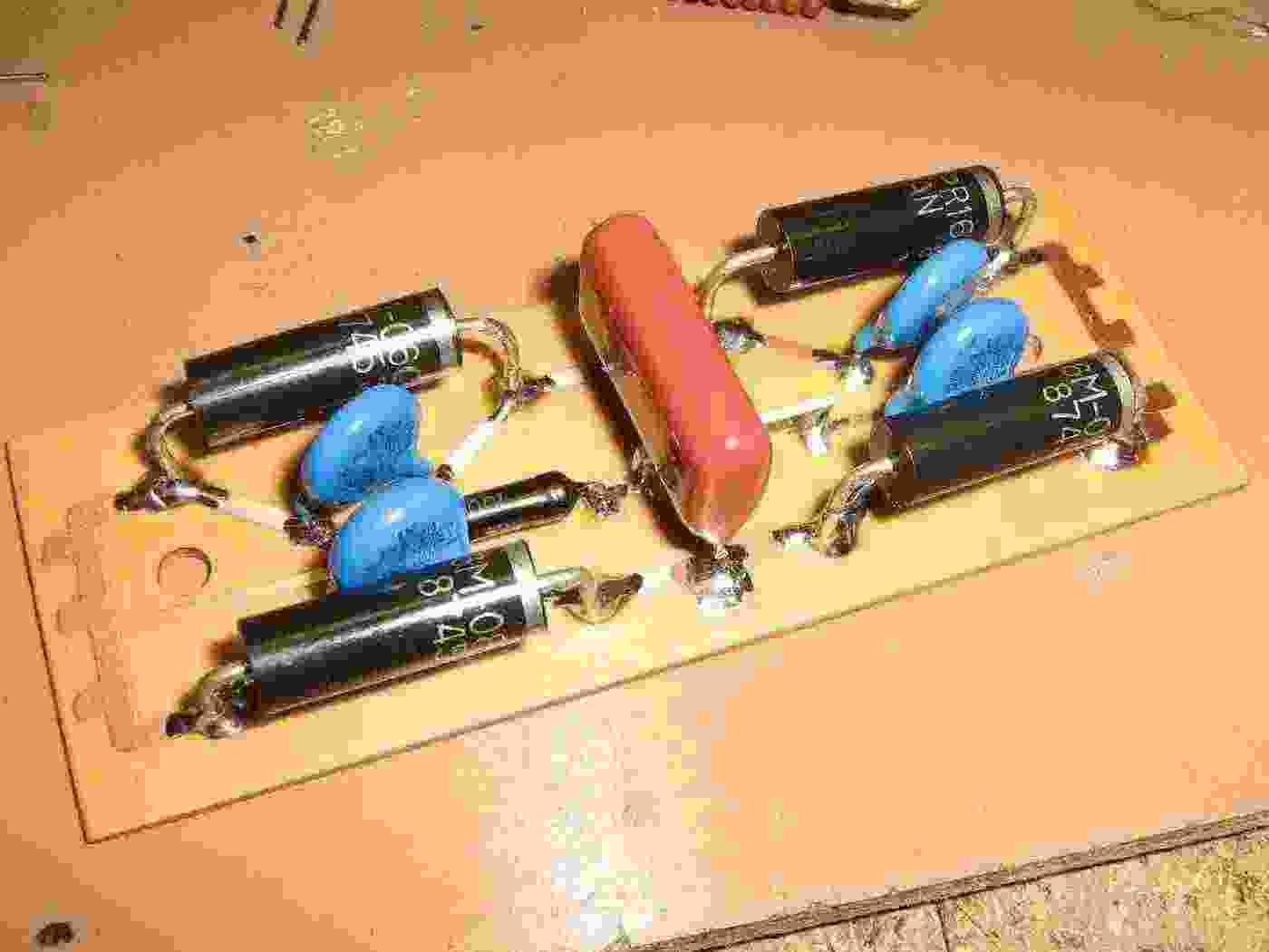
Solid-state, high-voltage bridge rectifier circuit.
The four diodes are HVPR16-06, but you can also use the high-voltage diodes from a microwave oven's voltage-doubler circuit, if they're the same. Each of the high-voltage diodes has a 3,300 pF / 3 kV capacitor across it. These are to help suppress any switching transients.
The red capacitor is a 8,200 pF / 3 kV, and is wired across the microwave oven transformer's secondary output. This is to also help suppress any high-voltage transients.
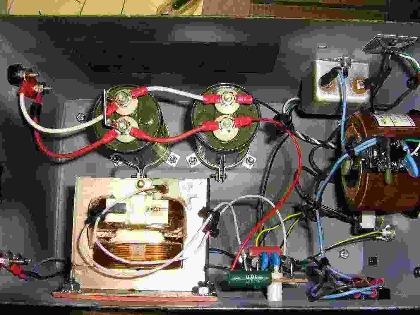
Completed high-voltage power supply internal overview.
A 10 ohm / 5 watt resistor was added in series from the bridge rectifier's positive DC output to help tame any current surges which could destroy the high-voltage diodes.
The microwave oven transformer is mounted against a sheet of rubber gasket to dampen any vibrations. The transformer doesn't need any extra high-voltage isolation in this application.

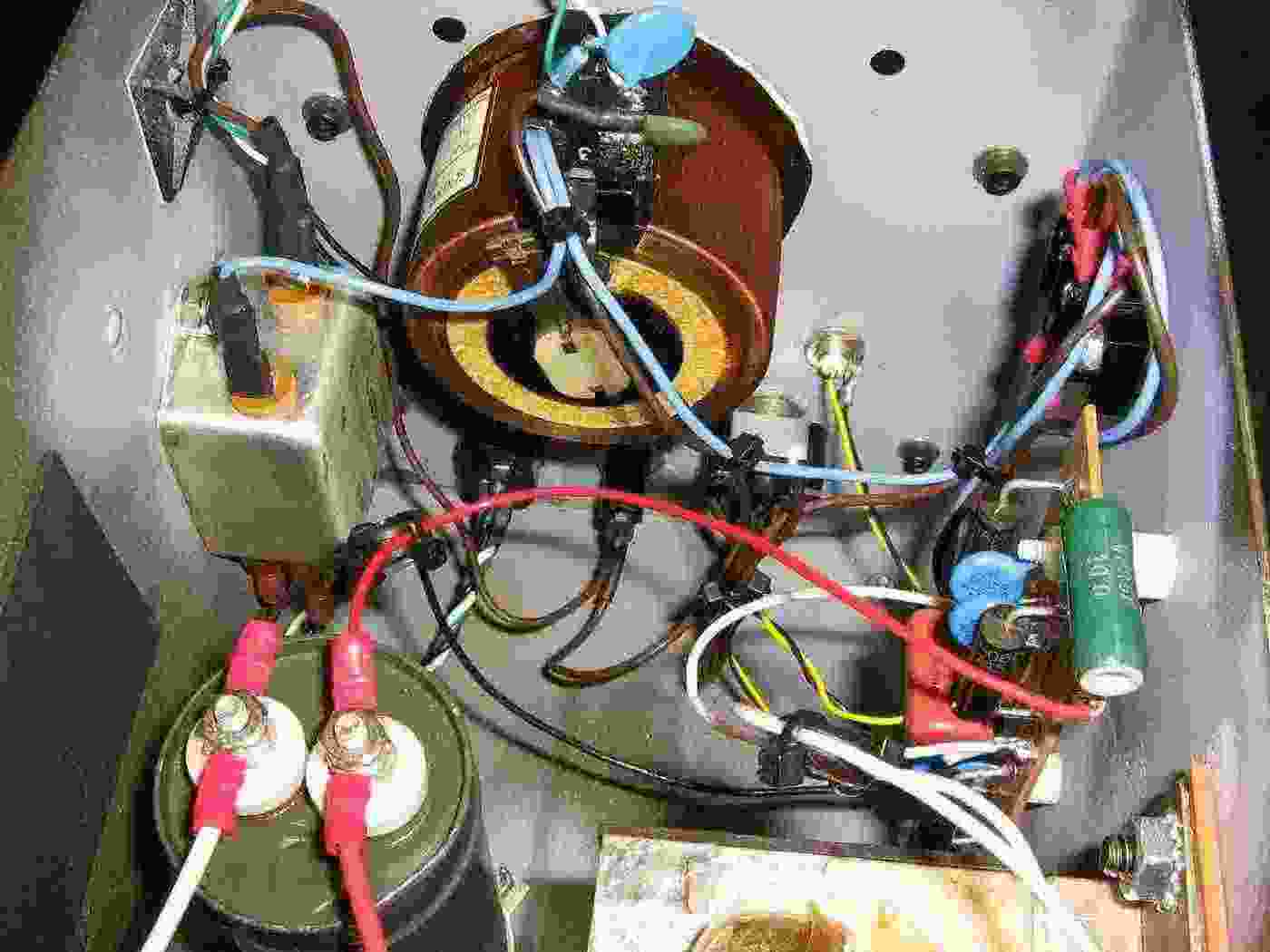
Completed high-voltage power supply internal overview. Alternate view.
Note the 10 Megaohm resistor across one of the high-voltage filtering capacitors on the right.
Also note the use of rubber grommets and zip ties to isolate and secure any wires carrying high-voltage.
The high-voltage output is via the two isolated banana jacks on the upper-right. A ferrite bead was slipped over the positive output wire.
The output of the Variac is tapped, ran through a fuse, and sent to the banana jacks on the upper-left.
Overview showing behind the front-panel and the Variac wiring.
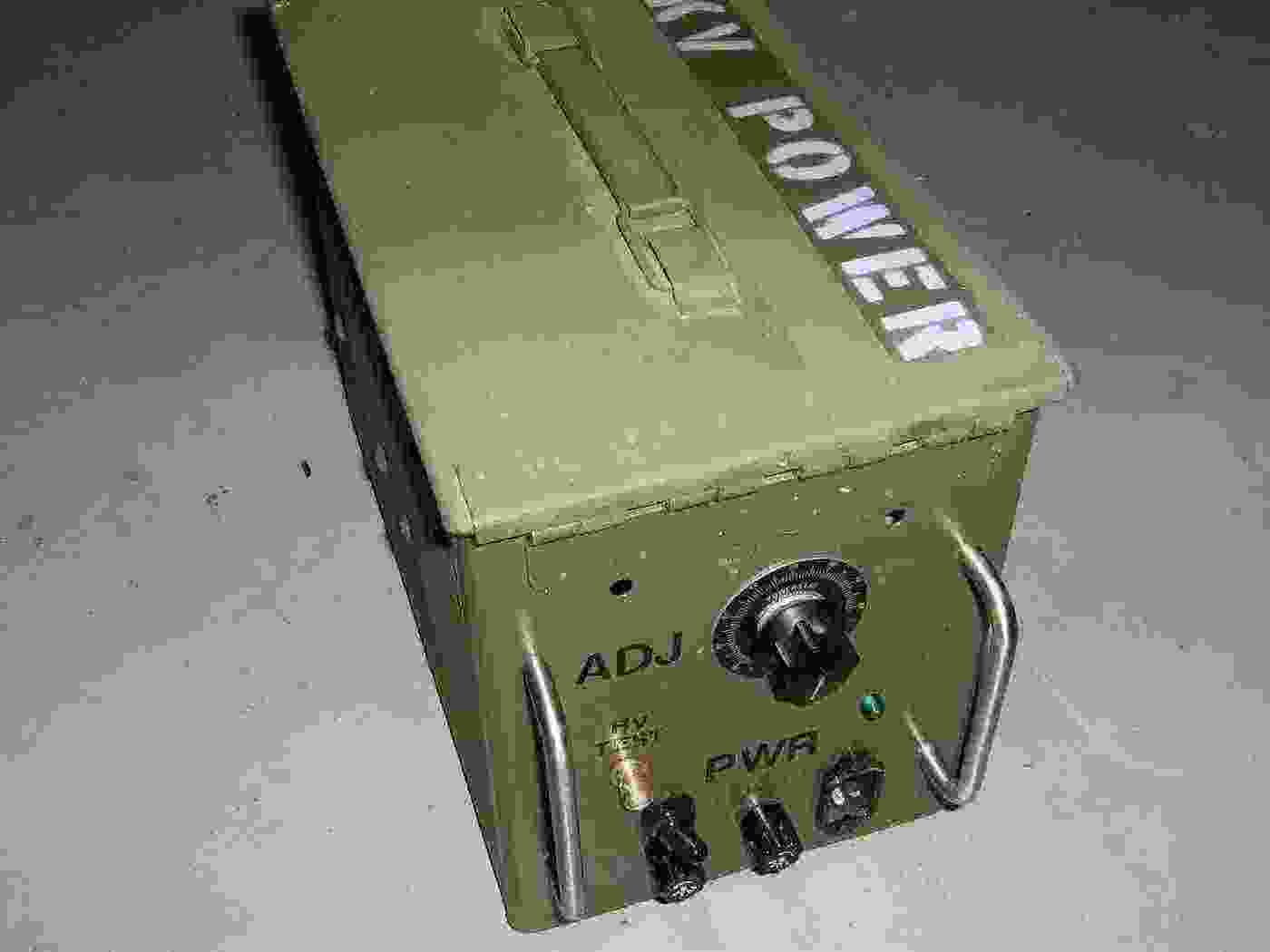
Completed high-voltage power supply overview.
The final DC output is adjustable from 0 to 2,500 VDC, but we'll only be using an output of 2,000 VDC for this radar project.
The BNC jack provides a "divide-by-100" voltage test point. It should read "20 Volts" when the power supply is set to an output of 2,000 VDC.