GBPPR Homebrew Radar Experiment

Magnetron Pulse Transformer


Overview

The magnetron pulse transformer is a passive device which couples both the high-voltage pulse from the modulator and low-voltage filament current to the radar magnetron's cathode/filament connection.  This is another important section of our homebrew radar project, and another one which I have no idea how to build!  The overall electrical concepts are well documented, but I've yet to find any decent documentation on all the nitty-gritty little details you need to build such a device.

The magnetron pulse transformer we'll be building will have a 1-to-4 "step-up" turns ratio.  This is because our radar modulator outputs a 1,000 volt pulse and the 2.45 GHz magnetron we are using needs to see around 4,000 volts.  The transformer's primary winding will be 10 turns of #20 enameled wire and the secondary will be 40 turns of bifilar-wound #18 enameled wire.  The transformer's core will be from a salvaged computer monitor's (CRT) high-voltage switching power supply.  The secondary winding will also need to carry the fairly high-current (10 Amps) for the magnetron's 3.3 VAC filament voltage.  In order to maintain the sharp rise and fall times for the magnetron's trigger voltage pulses, and to avoid any distortion, the actual number of turns making up the transformer should be quite low.  You'll also want to maintain low-leakage inductance and proper high-voltage isolation between the transformer's core itself and the primary and secondary windings.  To help with high-voltage insulation within the transformer, you can wrap the core's legs and windings with several layers of Teflon plumber's tape.  This tape will also protect the enameled wires from the ferrite core's sharp edges.

This transformer will also perform the proper impedance matching between the magnetron and the modulator's Pulse-Forming Network (PFN).  Using a transformer with a 1-to-4 turns ratio will transform the 100 ohm source impedance of our PFN, which is connected to the primary, up to a load of around 1,600 ohms on the secondary.  With an approximate 4,000 volt output and 1,600 ohm load impedance, the peak current through the magnetron will be around 2.5 Amps.  Some magnetron's may not like this high of a current pulse, so there may be some experinenting still to come.

With an efficiency of around 40-50%, we could possibly get a microwave oven magnetron to emit a peak RF pulse between 4,000 and 5,000 watts for a microsecond or so.  That is, of course, if the magnetron doesn't arc over or go into "mode" conditions where it doesn't oscillate or oscillates at the wrong frequency.  That little 2.45 GHz CW magnetron in your kitchen really isn't made for this pulse application, but we'll try...

For the transformer's core, we'll be using the retangular ferrite core from an old computer monitor's high-voltage "flyback" switching power supply.  I have no idea if this is the proper ferrite core material to use, or if a powdered-iron core may be better, but you should be able to find these ferrite cores for free.  Powdered-iron cores tend to handle higher temperatures a little better than ferrite cores and won't easily saturate under a high current load.

A standalone low-voltage (3.3 VAC) transformer will be needed for the magnetron's filament.  You can sometimes find these transformers in older microwave ovens, or you can just tap the low-voltage winding from a regular microwave oven transformer.  The transformer should have proper high-voltage (+4 kV) insulation.

Pictures & Construction Notes

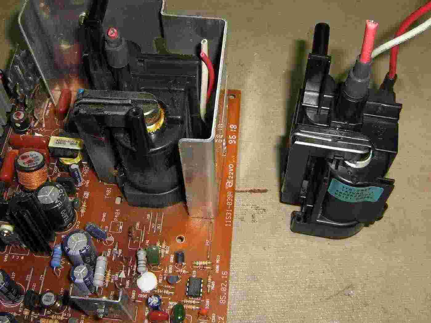
The high-voltage "flyback" switching power supply section in an old CRT-based computer monitor.

The power supply's transformer windings are wrapped around a large ferrite core.

The ferrite core is split into two pieces and may be glued into place.

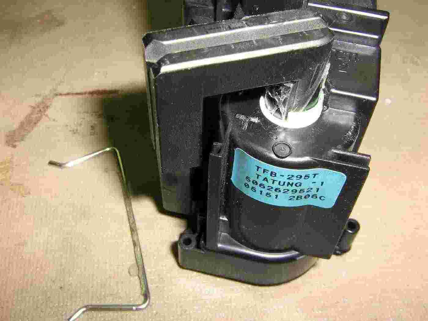
Remove the retaining clip and use a hot air gun to heat the entire transformer assembly.

Very gently tap the sides of the transformer with a rubber mallet to help loosen the glue.  If the ferrite core does break, it is possible to glue the broken pieces back together, but this is not recommended!

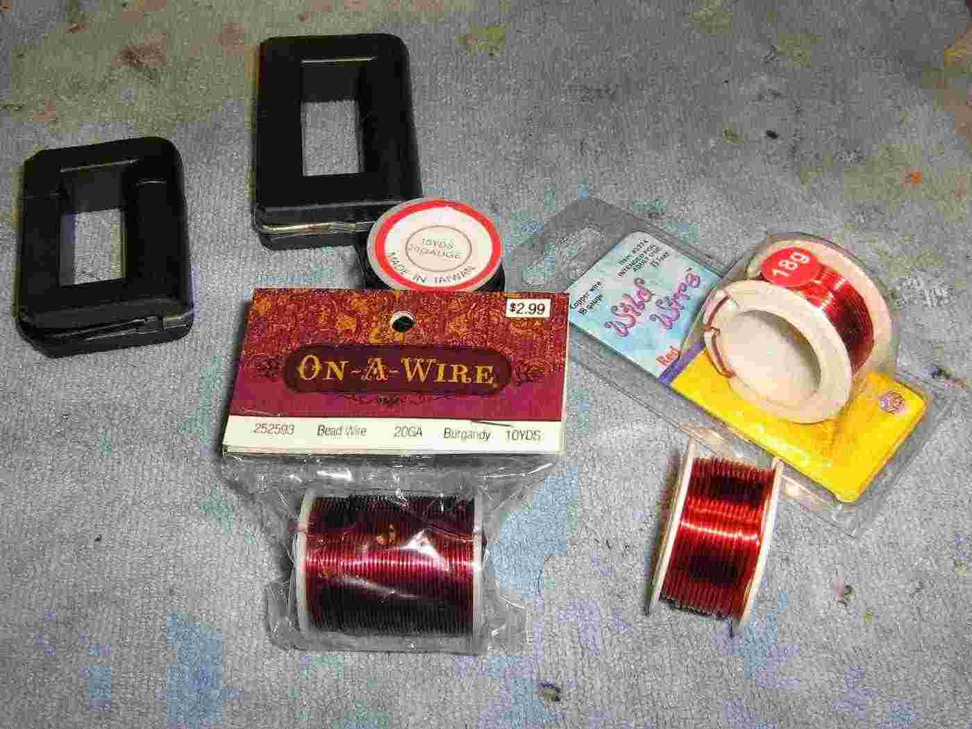
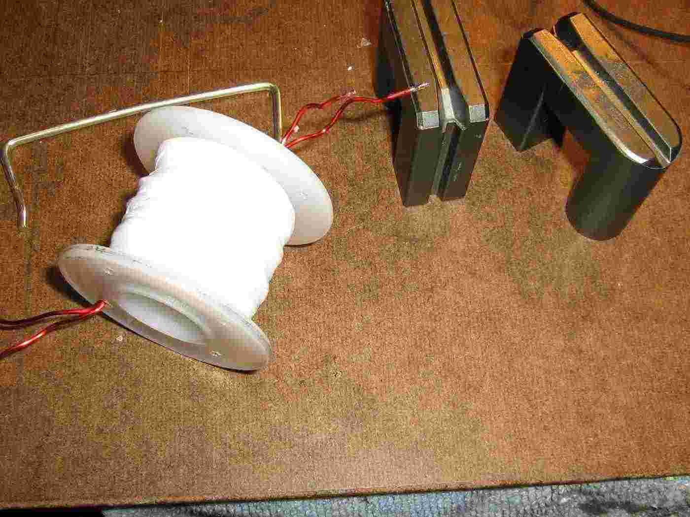
The enameled wire we'll be using and some example ferrite cores on the upper-left.

Believe it or not, you can buy small rolls of enameled wire at hobby stores like Hobby Lobby and Michaels.  They should stock different colors of #18 and #20 (and smaller gauges) of enameled wire for use in homemade jewelry and other stupid girl stuff.

For the secondary winding, try to use the largest wire gauge available to help reduce the voltage drop caused by the large current draw from the magnetron's filament.

Try to use different colored wires to help identify each winding.

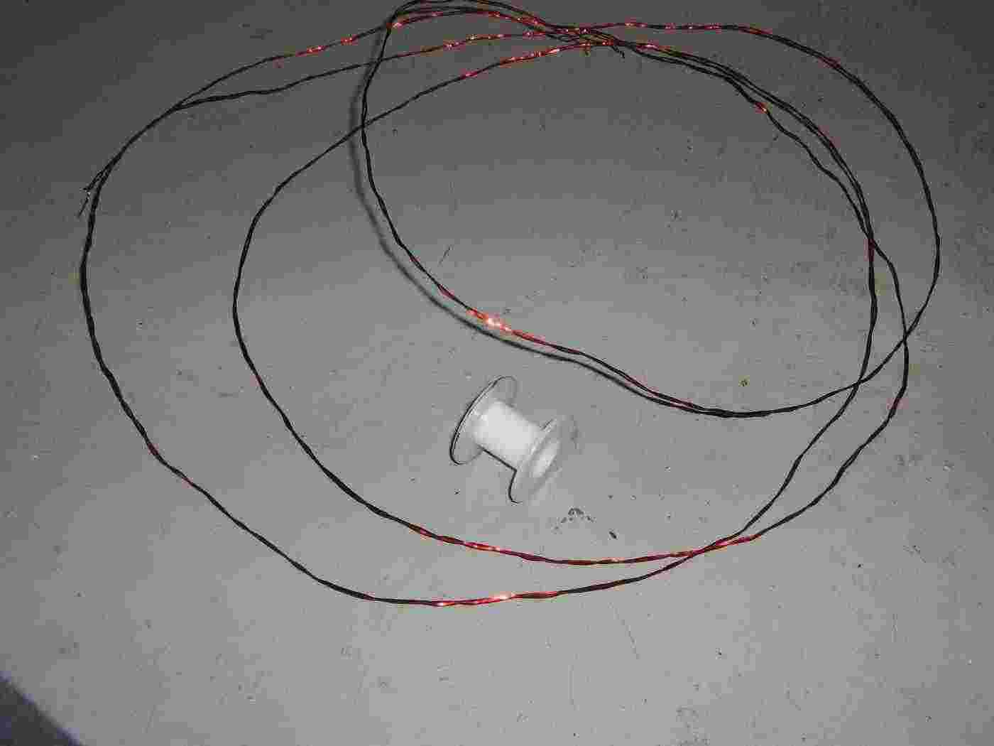
Bifilar wind (i.e. twist together) two pieces of #18 enameled wire.

I forget the final length you need, but I think it was around 13 feet.

You don't need very many "twists per inch," just loosely twist the two wires together to prevent them from coming apart.

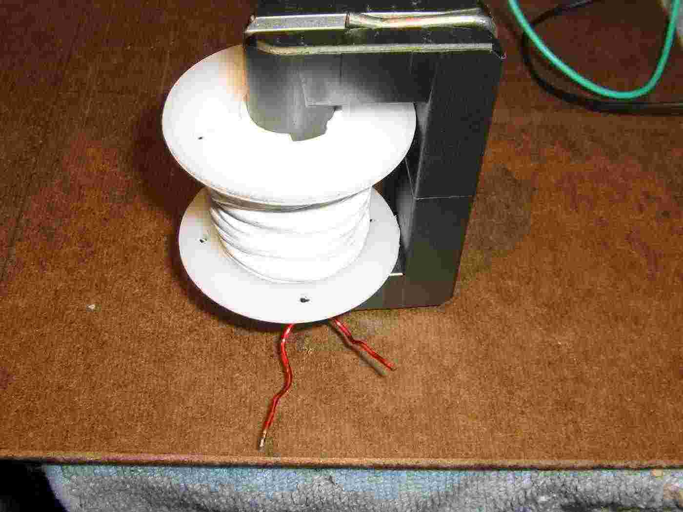
We'll be wrapping this secondary winding on an old plastic bobbin from the pre-tinned #24 bus wire you can buy at Radio Shack (#278-1341).

Wrap a layer of double-sided tape on the plastic bobbin before winding the 40 turns of the secondary to hold the initial windings in place.

When finished, wrap the entire coil with several layers of Teflon plumber's tape.

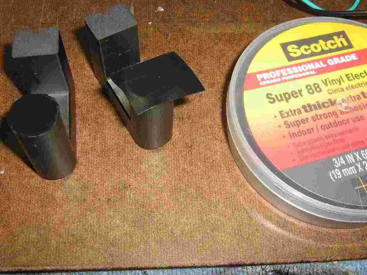
In order to keep the ferrite core from saturating, you can add a small air gap to one of the core's legs.

I have no idea how large this gap should be (the equations make no sense), so I just used two layers of 3M Super 88 electrical tape.

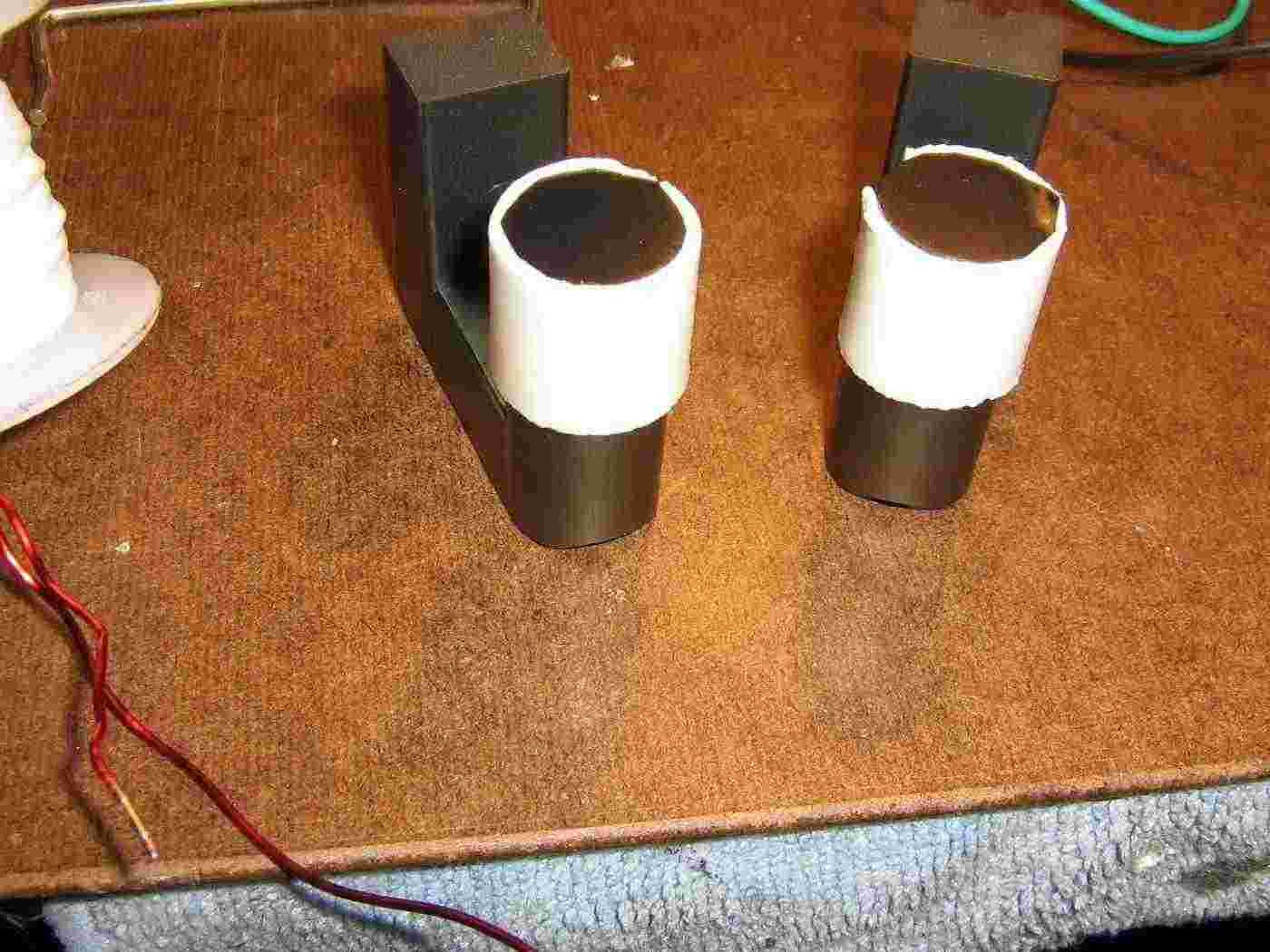
To secure the secondary coil to the ferrite core, wrap the legs with some double-sided tape.

Add as many layers that are needed to prevent the coil assembly from moving.

Center the coil form around the ferrite core's legs using double-sided tape to fill any gaps.

Be sure to attach the ferrite core's retaining clip and identify and label the each of the wires which make up the primary and secondary windings.

You'll need to watch out for polarity issues when finally connecting the transformer.

Winding the 10 turn primary.

Secure the wires using double-sided tape, then secure them with several layers of Teflon plumber's tape.

The final inductance measurements for this transformer were:

           Turns        Wire Gauge     Measured Inductance

Primary    10           #20            67 µH
Secondary  40 bifilar   #18            620 µH per winding

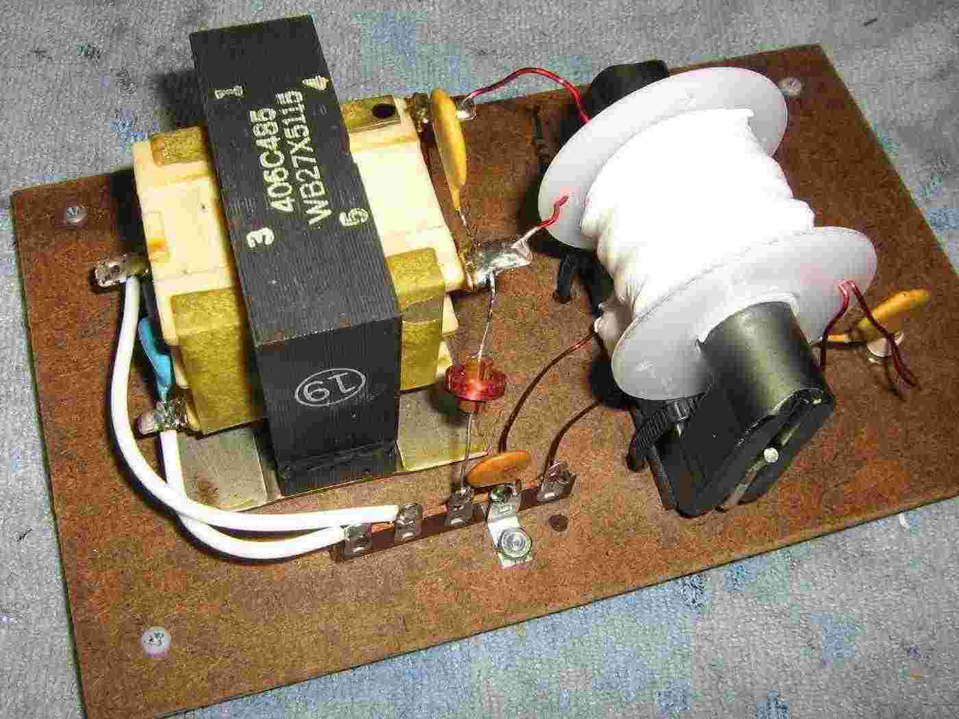
Completed magnetron pulse transformer with the matching filament transformer.

This entire assembly is mounted on some old clipboard material to help with proper high-voltage isolation.  The ferrite core is secured using some pieces of foam and zip-ties.

The 3.3 VAC magnetron filament transformer is on the left, with its 120 VAC primary input connections brought out to some solder terminals (white wires).

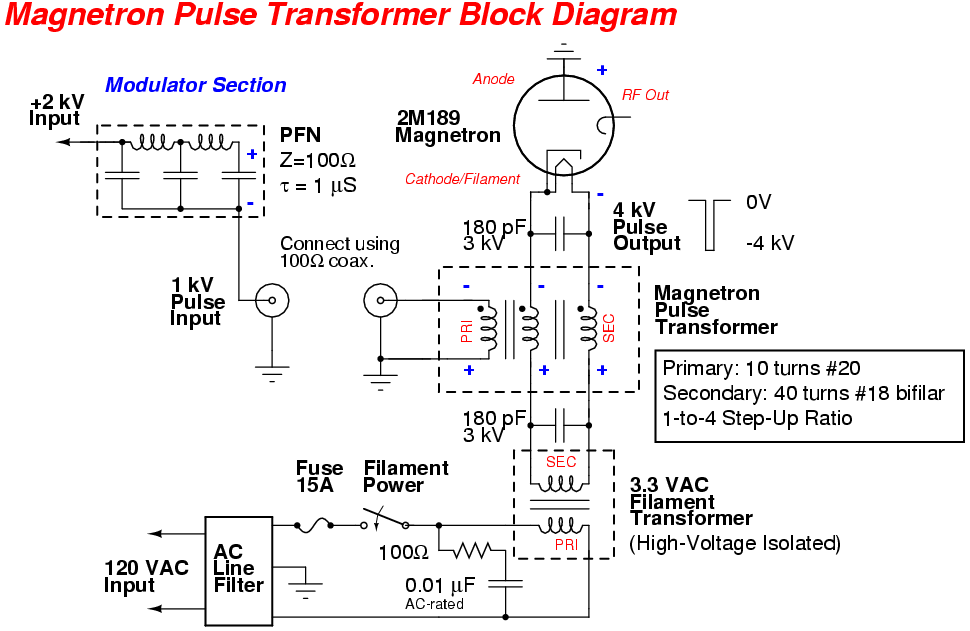
The 180 pF capacitors help to "even out" the voltage pulse between the two secondary windings before it is applied to the magnetron.

In the above photo, one of the secondary windings is tapped with a series 1 mH inductor and 0.01 µF capacitor to ground.  This forms a little low-pass filter to see if it's possible to measure the magnetron's average current.  This is optional and very experimental right now.

I have no idea what ferrite material this transformer core is made out of, but an old issue of QST mentioned some of them use "Ferroxcube 1F19-3C6A" material.

The ferrite deflection yoke from around the neck of an old TV or computer monitor CRT may also work, and can also be found for free.

Schematic

Practical Transformer Handbook

(Excerpt from Chapter 5 - High-Voltage Transformers)

Radar Transmitters

(Chapter 4 - Pulse-Transformer Design and Fabrication)

A Textbook of Radar

(Excerpt from Chapter 5 - Modulators)

Radar for Technicians: Installation, Maintenance, and Repair

(Excerpt from Chapter 2 - Introduction to Radar Transmitters)

Notes & Datasheets


Return to GBPPR Homebrew Radar Experiment Page