Overview
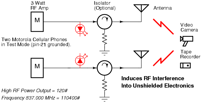
This is a device to remotely cause RF interference in unshielded electronic devices (cameras, microphones, recorders, etc) by using two old "bag"-style Motorola AMPS cellular phones, in continuous transmit, via the test mode commands.
It works by the mixing of two RF carriers in the non-linear junctions contained in most semiconductor components (transistors, diodes, ICs). If you were to flood an electronic device with two signals, say 837.000 MHz and 837.001 MHz, the non-linear junctions would mix the two signals to form the cross-products of 837.000 +/- 837.001 MHz and 837.001 +/- 837.000 MHz. The 837.001 - 837.000 MHz product is the one we are most interested in, as that produces an output frequency of 1 kHz (1000 Hz), which is a tone in the audio spectrum and something most electronic devices will respond to.
When pointing this "jammer" at a recording device, say a tape recorder, the recorder's output signal (to the recording tape) would be flooded with the 1000 Hz tone - essentially bypassing the microphone - and hopefully rendering the device useless.
Natural noise and other imperfections mean that even though the two cellular phones are programmed to transmit at the same frequency, they are never exactly the same frequency at the same time. They will always be withing a few hundered Hertz of each other. This causes a natural "warbly" jamming signal to be produced.
Block Diagram & Schematics
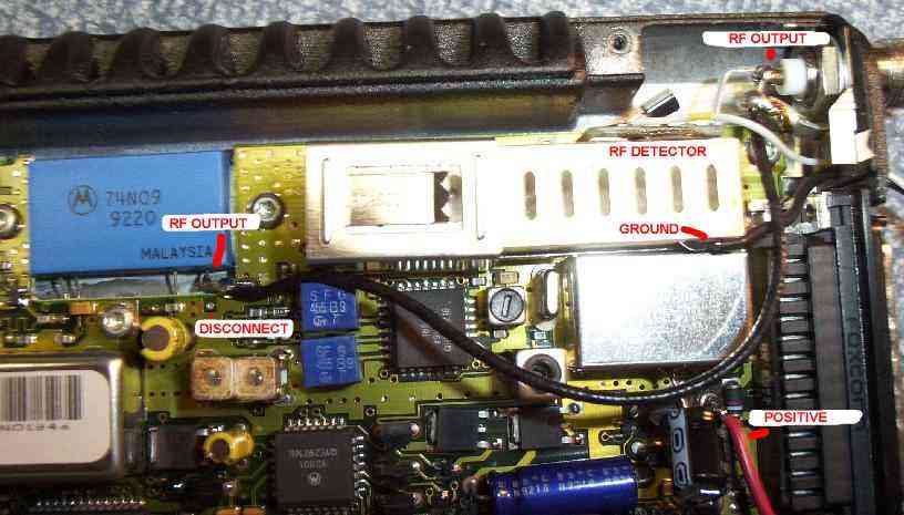
The isolators on the phone's RF output help prevent "RF feedback" from disrupting the phones themselves. These isolators are highly recommended, but can be difficult to find. Search hamfests or Fair Radio for 800 MHz isolators from old cellular site installations.
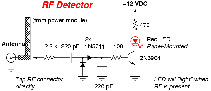
This is a little additional (and optional) circuit which will light an LED when strong RF is detected. It is useful for a quick visual verification on the phone's transmitting status. A bug with this circuit is that RF from the other phone can feedback into the diode detector and the LED will light anyway. The above mentioned isolators will cure this problem, or just increase the value of the tap resistor (2.2k).
Test Mode Commands
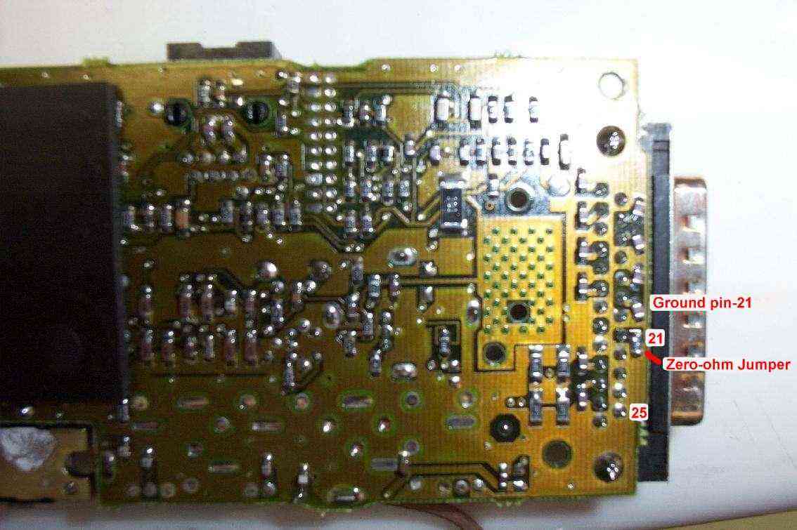
To place the older bag-style Motorola cellular phones into test mode, you'll need to ground pin-21 on the phone's DB-25 connector before powering up the phone. This is shown below:
On power-up in test mode, the handset LCD screen will start flashing random numbers.
Example: 314 059
To set the transmit frequency and RF output power level, enter the following keypad commands:
Press [#] to get to the U5 ' prompt. This is the test mode prompt where all the commands will be entered from. (Note: the U5 stands for U.S.)
Enter the frequency you want to transmit at. This can be anything from 824.04 MHz to 848.97 MHz in 30 kHz steps. You'll need to enter the frequency in "Motorola Test Mode" channel format. This is explained further in the infamous "Motorola Bible". Example: to transmit at 837.00 MHz, cellular channel 0400, you'd enter:
[1] [1] [0] [4] [0] [0] [#]
You'll need to increase the transmitter RF output to the maximum of 3 Watts (for this particular model phone). To do this, enter: [1] [2] [0] [#]
To turn the transmitter RF carrier on enter: [0] [5] [#]
Verify with a frequency counter or communications receiver that it is indeed transmitting at 837.00 MHz.
Repeat the sames steps for the second phone, but only turn the second phone's transmitter RF carrier on when you need to commence the jamming.
Pictures & Description
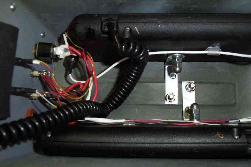
Picture of the DB-25 connector on the phone. The RED wire is the 12 VDC (positive) supply lead, the BLACK wire is the ground (negative). The small white/yellow wire is for the RF power output LED. The phone's mini-UHF connector was replaced with a TNC connector and an L-bracket was added for mounting. Pins 2 & 3 and 4 & 5 on the DB-25 connector must be tied together if you don't power the phone via the normal battery or cigarette connector.
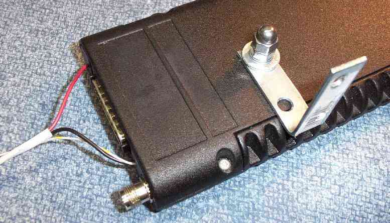
Internal phone view. RF output is tapped directly from the hybrid power module's RF output pin. This increases the output power level slightly by not having to pass through the duplex filter. This is optional. A small diode detector circuit was added for a visual indication of RF output. You can also see where the DC power supply leads are connected. The RED positive lead is soldered directly to the protection diode. The BLACK negative lead is soldered to the duplex filter. Also, a small 10 uF bypass capacitor was added from the protection diode to ground.
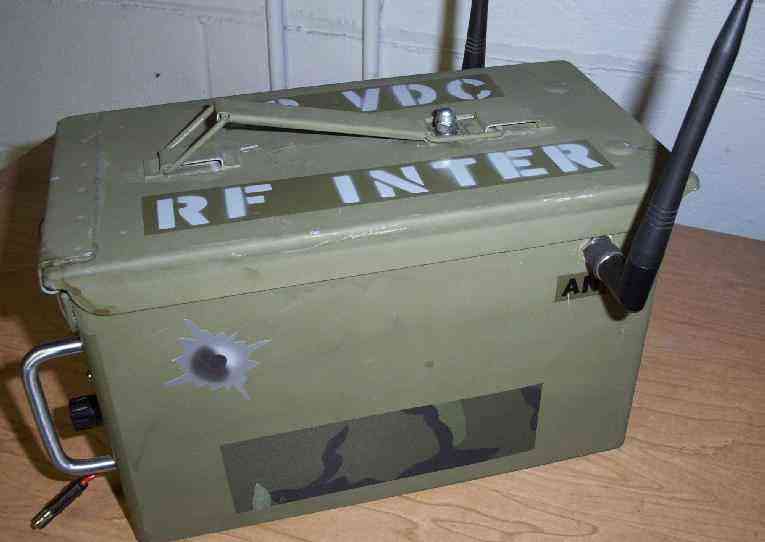
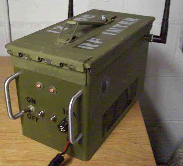
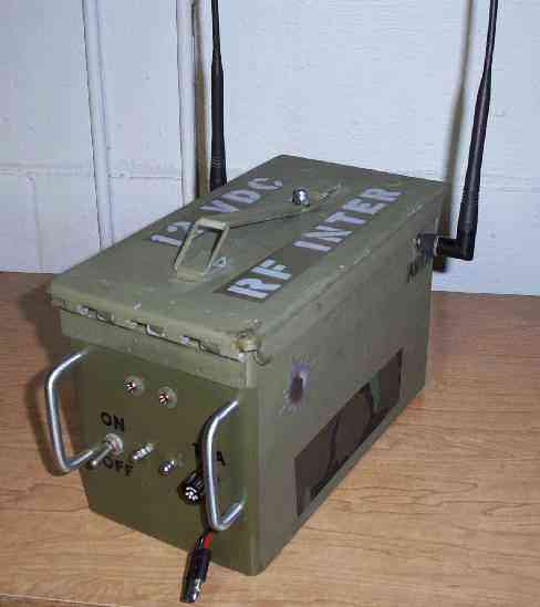
Outside case overview. Built into an old .30 caliber military ammo box. All holes and RF connectors are sealed with rubber washers to improve water resistance. All hardware is stainless steel. The phone's original mini-UHF connectors where salvaged and panel-mounted for use with the original antennas. The front-panel protection bars are brass drawer handles. Camouflage is the standard Western Europe green. Lord knows it's just a matter of time before those bastards kill millions of people again and I'll need to carry all my hardware there to kill, err, protect them...
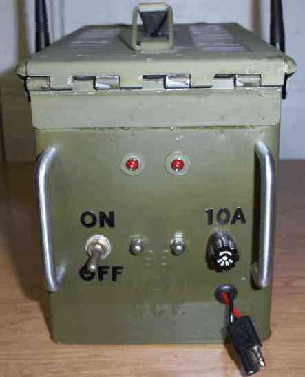
Front-panel overview. The two red LEDs indicate RF output. The +12 VDC power supply is protected with a 10 amp fuse. The two phones in "high-power mode" will draw around 6 amps continously.
Side view. Those are the phone's original, stock, unity gain, "rubber duck" antennas. They work very well for transmitting across the entire 800 MHz band.
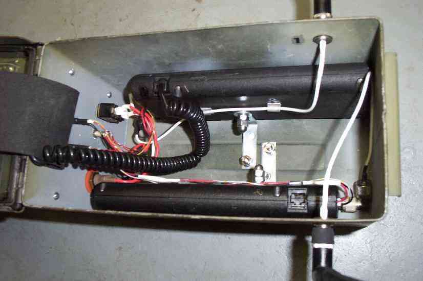
Internal case view. Each phone is mounted via its bracket to the bottom of the ammo box. Only one handset is needed for the issuing test mode commands. The phones will still transmit even if the handset is removed.
Close up internal view behind the front-panel. A piece of flexible foam (far-left) flips down to protect the exposed terminals and wires.
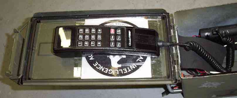
Handset picture. The handset is bolted to the ammo box's cover. Be sure it doesn't pinch the cable when closing. A large CIA logo is underneath the handset.
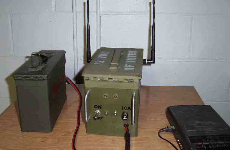
Testing setup. The green ammo box on the left is a large 12 volt lead-acid battery. The jammer is in the middle and the "victim" tape recorder is on the right. The effective jamming radius of this setup was only about a meter. More RF power output and/or directional antennas will increase the range.
Jammer in operation. I was hoping it would "jam" the digital camera's picture, but alas it only interfered with the camera's LCD screen. The picture came out fine - but doesn't appear as sharp.
Notes
- The Motorola Bible v3.0 by Mike Larsen
- Motorola Bag Phone Handset Control Control a Motorola cellular phone's handset with a simple PIC circuit.
- Russian STORM Portable tape & digital recorder suppressor
- Rice Car Audio Disruptor