The Physical Nature of PEMIN as the Basis for the Formation of Information Leakage Channels
Response methods
An attack must not only be detected, but also responded to correctly and promptly. Existing systems employ a wide range of response methods, which can be divided into three categories [9, 40]:
• notification;
• saving;
• active response.
The application of a particular reaction depends on many factors¬.
Notification. The simplest and most widespread notification method is to send messages to the security administrator about an attack on the console of the attack detection system. Such a console may not be installed on every employee person responsible for security in the organization; in addition, these employees may not be interested in all security still events, so other notification mechanisms must be used. These mechanisms can be sending messages by email, pager, fax or telephone.
Category notification also includes sending control sequences to other systems, such as network management systems or MEs.
Saving. Two response options fall into category storage¬:
• registration of an event in the database;
• playback of the attack in real time.
The first option is widespread in other systems
protection. To implement the second option, it may be necessary to let the attacker into the company’s network and record all his actions. This allows the security administrator to then reproduce in real time (or at a given speed) all the actions carried out by the attacker, analyze successful attacks and prevent them in the future, as well as use the collected data during the investigation.
Active response. The following response options fall into this category:
• blocking the attacker’s work;
• session termination with the attacking node;
• control of network equipment and security tools.
IDS can offer the following specific response options: blocking the attacking user’s account, automatically terminating the session with the attacking node, reconfiguring the ME and routers, etc. This category of response mechanisms, on the one hand, is quite effective, and on the other hand, requires careful use, since incorrect application can lead to disruption of the functionality of the entire CIS.
In electronic systems where the information carrier is an electrical signal, its parameters (current and voltage) change in accordance with the transmitted messages. These processes occur in information circuits of technical means. In addition to information, in technical means there are also non-information circuits such as power circuits, synchronization circuits, etc. These processes are schematically shown in Figure 2.
The structure and strength of scattering fields, created by technical means and systems, depend on the type of information signal circulating in information circuits, dimensions, and design features of technical means. Taken together, they represent an electromagnetic field created by an extended transmitting antenna, changing according to the law of the information signal and propagating in the environment.
For the simplest case, to which many real situations can be reduced, the structure of the electric and magnetic fields of the harmonic components of any spectrum of informative signals in the space surrounding the operating technical device can be considered on the basis of solutions to Maxwell’s equations for the emitter in the form of a symmetrical vibrator.
|
| Channels of information leakage due to informative spurious electromagnetic radiation and interference
|
|

|
| 1. Caused by informative electric and magnetic scattering fields
| 
|
|
| 2. Caused by informative signals induced in various conductive media
|
| 3. Caused by parasitic modulation of signals from high-frequency generators with informative (provoking) signals
|
|
| | | | | |
Figure 2 - Information leakage channels due to electromagnetic radiation and interference
The strength values of the magnetic and electric fields created by a symmetrical vibrator can be found using the formulas:
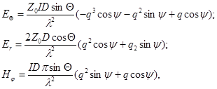 (1)
(1)
where E and H are the strength of the electrical and magnetic components of the field; q = l/ 2p r, r - length of the radius vector;
Z0 = 377 Ohm - free space characteristic impedance;
I - current in a symmetrical vibrator;
D - optimal length (dimensions of emitters) of the total extended antenna (technical device);
q is the polar angle;
j - longitude;
y = (2p r)/lw t, w - circular frequency, t - time.
The formula is valid provided that D <<l (D are the dimensions of the emitters).
Analysis of expressions (1) shows that there are three zones around the technical tool. In the first (near), for which r < l/2p, H decreases proportionally 1/r 3, in the second (further), for which 3l < r, H decreases proportionally 1/ r, in the third (intermediate), for which l/2p< r <3l, H decreases predominantly in proportion to 1/r 2. At the same time, the distance from the zone boundaries to the technical device is greater, the greater the l, i.e. less frequency f.
In the near zone, the distance r is significantly less than the wave of the electromagnetic signal - (r << l/2p) and the field has a pronounced magnetic (or electrical) character, and in the far zone (r >> l/2p) - the field is of a clear electromagnetic wave nature and propagates in the form of a plane wave, and the greater the distance r, the weaker the field. There is a scattering effect.
A more accurate model of a technical device, which is predominantly a source of radiation in the form of an electric field, is an asymmetrical vibrator placed above a perfectly conductive surface of the earth. For such a model, the reflection of signals from the earth's surface is taken into account. The model that comes closest to reality is one that takes into account the conductivity of the earth. In this case, the resulting field strength at the receiving point is enhanced.
In the first type of channels, the wavelength determines the distance, therefore, it is legal to divide emitters of electromagnetic signals into low-frequency, high-frequency and optical.
Low frequency emitters mainly include sound amplification devices. In the near zone of such devices, the magnetic field of the dangerous signal appears most powerfully. Such a field is easily detected and received by means of a magnetic antenna and a selective audio amplifier.
The group of high-frequency emitters includes RF self-oscillators, RF oscillation modulators and devices that generate parasitic RF oscillations for various reasons and conditions. The sources of the dangerous signal are RF generators of radios, televisions, measuring generators, and computer monitors. HF oscillation modulators, like elements with nonlinear characteristics (diodes, transistors, microcircuits), generate undesirable components of an HF nature.
The second type (see Figure 2) of information leakage channels is formed on the basis of the appearance of parasitic connections (tips) p of a different nature between the information circuits of the main and auxiliary technical means and various conductive media, in most cases not directly related to the information processed using this technical means. Informative currents in these environments, arising due to the leakage of signals from information circuits in them, propagating in these environments, can be intercepted outside the controlled area.
In addition, they are sources of secondary informative radiation, which can also be recorded, and the processed information can be reconstructed from them.
A random antenna is a circuit of an auxiliary technical device or extraneous conductors capable of receiving side electromagnetic radiation. Random antennas can be concentrated and distributed (extended). A concentrated antenna is a compact technical device (telephone device, relay network loudspeaker, security alarm sensor, etc.). Distributed (extended) random antennas include random antennas with distributed parameters: cables, wires, metal pipes and other conductive communications (propagation media).
Such environments generally include:
- grounding system and power supply network for technical equipment;
- communication circuits located in the same cable in which there are information circuits - sources of intercepted information;
- various communication lines having parallel runs with information circuits - sources of intercepted information, as well as with power lines and grounding buses of technical means - sources of information;
- various metal pipelines (heating and ventilation systems), metal structures of buildings and other extended conductive objects.
The source of the formation of the third type of channels (see Figure 2) is, as a rule, unintentional modulation of high-frequency signals HF generators (or amplifiers) available in technical means (in their non-information circuits), information signals penetrating into them from the information path due to parasitic connections. As a result, a more dangerous technical channel for information leakage is formed than the channels that arise during the passage of operating information signals.
The main types of parasitic connections in circuits of electromagnetic devices are capacitive, inductive, electromagnetic, electromechanical connections and connections through power supplies and grounding of radio-electronic devices.
For digital integrated circuits, in addition to parasitic generation, which in principle can occur in any active (logical) elements, generation is isolated due to parasitic oscillations that occur in connections between microcircuits (due to inconsistency in the impedances of circuit elements).
If amplifiers are included in the information path of a technical device, then when they operate unstable, self-excitation occurs in the operating frequency range or beyond.
Interception of spurious electromagnetic radiation from technical equipment is carried out by radio and electronic reconnaissance equipment located outside the controlled zone (protected territory).
Technical information leakage channels based on passive interception tools
Physical entity microphone effect
During the operation of some technical means, along with electromagnetic fields scattering, informative acoustic, vibroacoustic, hydroacoustic and acoustoelectric fields (signals) arise; during a telephone conversation - an electrical signal in the line and various directions and influences; During a radiotelephone conversation, an electromagnetic signal appears.
Acoustic energy generated during conversation can cause acoustic (mechanical) vibrations of electronic equipment elements, which leads to the appearance of electromagnetic radiation or its change under certain circumstances. The most sensitive elements of electronic equipment to acoustic influences are inductors and variable capacitors.
Let us consider the acoustic effect on the inductor with the core and the conditions for the occurrence of induction emf at its ends (inductive converter).
Under the influence of acoustic pressure, vibration of the housing and coil winding appears. Vibration causes oscillations of the winding wires in a magnetic field, which leads to the appearance of an induction EMF at the ends of the coil.
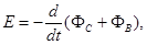
where ФС is the magnetic flux that closes through the core;
ФВ - magnetic flux that is closed through the windings through air.
The electromotive force depends on the magnetic induction vector, the magnetic permeability of the core, the angle between the vector and the axis of the coil and the cross-sectional areas of the core and coil.
Inductive converters are divided into electromagnetic, electrodynamic and magnetostrictive.
Electromagnetic converters include devices such as loudspeakers, electric bells (including calling electric bells of telephone sets), electrical and radio measuring instruments.
An example of the direct use of this effect for acoustic conversion purposes is the electrodynamic microphone (see Figure 3). The EMF at the coil output is determined by the formula:

where L = 4kpm0w2S/l - inductance;
k is a coefficient depending on the ratio of parameters;
l -coil winding length;
m0 - magnetic permeability;
S is the cross-sectional area of the coil;
w is the number of turns of the coil.
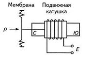
Figure 3 - Electrodynamic microphone
The appearance of an EMF at the output of such a converter is usually called the microphone effect. Thus, the microphone effect is the appearance in the circuits of electronic equipment of extraneous (parasitic) electrical signals caused by mechanical influence, incl. sound wave pressure. The microphone effect can manifest itself both in electrodynamic and electromagnetic, capacitor and other designs, and is widely used in microphones for various purposes and designs (including special ones). Information leakage channels formed on the basis of the microphone effect are called channels due to electroacoustic transformations, since their formation requires the conversion of mechanical vibrations into electrical signals. The elements in which the specified transformation is carried out are called electroacoustic transducers.
Let's give a classic example. A telephone set, even when its handset is at rest in its intended place (there is no conversation directly over the phone), can cause the formation of an information leakage channel due to electroacoustic transformations (microphone effect), since this call is a typical representative of an inductive acoustoelectric converter, a microphone effect that manifests itself when the handset is placed. Figure 4 shows a diagram of the telephone set.
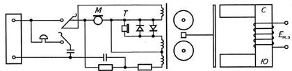
Figure 4 - Diagram of the telephone set
The electromotive force of the microphone effect of a bell can be determined by the formula:
Eme=h p,
where p is the acoustic pressure;
h = FSm0wSm/d2zm - acoustic call sensitivity;
F is the magnetomotive force of a permanent magnet;
S is the area of the anchor (plate);
m0 - magnetic permeability of the core;
w is the number of turns of the coil;
Sm - area of the flat tip;
d is the gap value;
zm - mechanical resistance.
On the same principle (of occurring physical phenomena in electromechanical ringing), a microphone effect is formed in certain types of electromechanical relays for various purposes (see Figure 5)
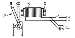
KS - contact system; K-coil, C – core
Figure 5 - Relay operation diagram
The armature oscillations change the magnetic flux of the relay, which is closed through the air, which leads to the appearance of an EMF microphone effect at the output of the relay coil. Elements of other technical means may also have similar properties.
Under the influence of an acoustic field, capacitive converting elements convert a change in capacitance into a change in electrical potential, current, voltage (linear characteristics of oscillatory circuits), which leads to a change in the parameters of the circuits according to the law of an informative signal (for example, oscillation of the membrane of the capacitor microphone of a telephone handset, which also, in turn, can rest on the telephone). Elements of electrical measuring instruments, various transformers (boosting, step-down, input, output, power, etc.) have a microphone effect.
Microphone effect of optical converters
In modern fiber-optic systems (FOCS) the process of information transmission uses modulation of the light source by amplitude, intensity and polarization. External acoustic impact on the fiber-optic cable leads to a change in its geometric dimensions (thickness), which causes a change in the path of light movement, i.e. to a change in intensity, and proportional to the value of this pressure. The microphone effect in FOCS for information transmission is obvious (the sensitivity of the light guide to pressure is determined by the value of the ratio Ch = Dj/jD p, where Dj is the phase shift caused by a change in pressure D p.
The study of the properties of solid dielectrics showed that some of them are polarized not only by an electric field, but also during deformation under mechanical action on them. Polarization of a dielectric under mechanical action on it is called a direct piezoelectric effect. Quartz crystals and all ferroelectrics have this effect (when quartz is compressed, its opposite faces are charged polarly and the charge value is proportional to the pressure, a corresponding electrical signal is formed at the output contacts). Quartz plates are widely used in piezoelectric microphones, security sensors, stabilizers of generators of undamped oscillations.
Air and vibration technical information leakage channels
Aerial and vibrational technical channels of information leakage are reconnoitered using special and highly directional microphones. In air TKUI, the medium for the propagation of information signals is the air medium and both hidden wired communication lines equipped with miniature highly sensitive microphones and special highly directional microphones are used to intercept them. Using such microphones, you can listen to a conversation at a distance of up to 1 km within line of sight.
A simple directional microphone is a set of seven aluminum tubes up to 10 mm in diameter. The length of the tubes determines the resonant frequency of the audio signal. The microphone is located in a parabolic catcher. The intercepted signal is amplified by a microphone amplifier. This directional microphone covers the entire spectrum of sound (speech) vibrations (300...3300 Hz). Expanding the range of received frequencies in order to ensure high quality of received speech signals is carried out by increasing the number of resonant tubes and changing their length, for which special engineering calculations are made (a system of 37 tubes, for example, provides overlap of the range from 180 to 8200 Hz).
In vibrating TKUI, the medium for the propagation of acoustic signals is the structures of buildings, structures, water supply pipes, heating systems, sewers and other solids and surfaces. In this case, contact microphones (stethoscopes) are used to intercept acoustic vibrations. Contact microphones connected to an electronic amplifier are called electronic stethoscopes.
Technical information leakage channels based on active interception tools
Technical embedded devices
Technical embedded devices (TCDs) are small-sized devices (up to the size of a pin head) designed to collect and transmit over sufficiently long distances (from several hundred to several thousand meters) both information processed, transmitted, etc. using technical means (hardware bookmarks) and speech information (radio microphones).
According to the range of work, technical specifications are divided into:
- radio bookmarks operating in the radio range;
- IR bookmarks operating in the infrared part of the spectrum.
According to the environment used to transmit the collected information (or transmitted in real time), radio bookmarks are divided into two groups:
- working on the radio;
- operating via communication lines, power supply networks and other conductive metal extended structures.
The most commonly used radio bookmarking range of the first group is 20...25; 130...174; 350...512 MHz. The second group of bookmarks operates in the range of 500...300 kHz.
In terms of design and tactical use, radio bookmarks are divided into:
- telephone (installed directly on phones) and
- microphones (acoustic listening to conversations indoors).
Radio microphone is a microphone combined with a radio channel for transmitting audio (acoustic, speech) information. Sometimes they are called radio bookmarks, radio capsules, sometimes - bugs (the most accurate is a radio microphone). Their popularity is determined by the simplicity and ease of operational use.
In the simplest case, the radio microphone consists of the microphone itself, which determines the acoustic sensitivity zone of the TZU (20...30 m) of the radio transmitter, which determines its range, stealth of operation and emits a carrier frequency modulated by electrical signals from the microphone into space. The type of radio receiver has a significant impact on the length of the radio channel. The TZU may include a recording device and a control device (for switching on at the beginning of a conversation, voice, transmission mode - either in real time or pulse, adjusting the carrier frequency, etc.).
Some hardware technical specifications are not intended to create TCUI, but to destroy, distort the processed, transmitted, received, displayed, etc. computer information and software, as well as to destroy individual components and boards of these devices.
Laser listening devices. A laser (one of the optical-electronic channels) channel for leakage of acoustic information is formed when a laser beam irradiates thin reflective surfaces (glass, windows, paintings, mirrors) vibrating in an acoustic field. The laser reconnaissance beam, hitting a vibrating reconnaissance object, is modulated in amplitude and phase (according to the law of vibration of the reconnaissance surface), reflected and received in a modified form (diffuse or mirror) by a laser radiation receiver; when demodulating the returned beam, speech information is released.
Laser listening devices (laser microphones) are complex technical systems that operate on the principle of location, usually in the near-IR wave range. The range of such systems is hundreds of meters.