GBPPR JAMCAT


Overview

This is a simple add-on jammer adapter for any amateur or two-way radio transceiver with an external microphone (PTT) and earphone/speaker connection.  The jammer will key (transmit) the radio on upon the detection of any "activity" on the particular frequency the receiver is tuned to.

This is the perfect type of jamming system to interfere with those pesky security guards, restaurant drive-throughs, corrupt police, or even LoJack and cellular/pager-type "quick bursting" radio transmission systems.

The construction of the circuit is quite simple.  Two LM358 dual op-amps are used to amplify and clip any audio signal coming from the jamming transceiver's earphone or speaker output.  This audio signal is what is used to trigger the transmitter portion of the transceiver.

The circuit assumes that any "noise" coming from the earphone or speaker output is the transceiver receiving a valid transmission, so be sure your radio's squelch setting is tight or none of this will work properly and you'll just be stuck jamming random signals!

The op-amps are configured to amplify and rectify any incoming audio signal.  This amplification and diode hard-limiting eventually turns the incoming audio signal into a square wave.

This square wave is further rectified to generate a positive pulse which is used to trigger a 555 timer in a monostable configuration with an adjustable delay time.  The output of the 555 timer toggles a relay which controls the PTT switch on the jamming transceiver causing it to transmit.

The 1 megaohm Delay Time potentiometer can be adjusted to increase/decrease the length of the 555 timer's "jamming" time.  Note that too low of a jamming delay time can result in "relay chatter," so set the delay time for a few seconds or longer.

The internal noise generator, which is optional, is just a standard 1N5235 6.8 volt Zener diode with a small reverse current and a 2N3904 transistor buffer.  The National LM386 audio amplifier acts as a natural band-pass filter and small-signal amplifier.  The noise jamming signal is then mixed with the PTT control line / microphone input to modulate the transmitter's RF output with a little bit of random noise.  This will help in masking the jamming transmission, making it look like just random "noise" to an outside observer.  With the noise generator disabled, the jamming signal will be an unmodulated RF carrier.

The only real "bug" in the circuit is the PTT control.  Some transceivers like to be keyed with a PTT-to-ground circuit, while some require a little bit of resistance to ground.  You may have to experiment with the 1 kohm resistor value, or check the radio's manual for the proper PTT control circuit.

It's also possible to replace the PTT control relay with a single transistor (2N3904, etc.), but the hardware relay will allow for more external control options when adapting to other gear.

Operation

  1. Tune your transceiver to the desired frequency to jam.  Remember, you want to jam the receiver of the target, so take this into account when a repeater system is being used.  Optionally, connect the transceiver to an external high-power RF power amplifier (or antenna system) to increase the effectiveness of the jamming.
  2. Connect the transceiver's earphone/speaker output jack to the GBPPR JAMCAT's Audio Input.  This will usually be via a 1/8" mono jack.  Use as low a volume as possible.  Also watch out for "speaker pops" when your radio unkeys.  Test ahead of time, if you can.
  3. Connect the transceiver's microphone/PTT jack to the GBPPR JAMCAT's PTT Control input.  This will usually be via a 3/32" mono jack.
  4. Adjust the squelch on the transceiver to the desired setting.  "Tight" squelches are best, that is, squelches which require a strong received signal before they "open."  This helps in eliminating the receiving of random RF interference or noise, and prevents any unnecessary jamming transmissions which could potentially reveal your jamming location.
  5. Select either the internal noise modulation or use an external line-level modulation source, such as tones, speech, music, etc.

Pictures & Construction Notes

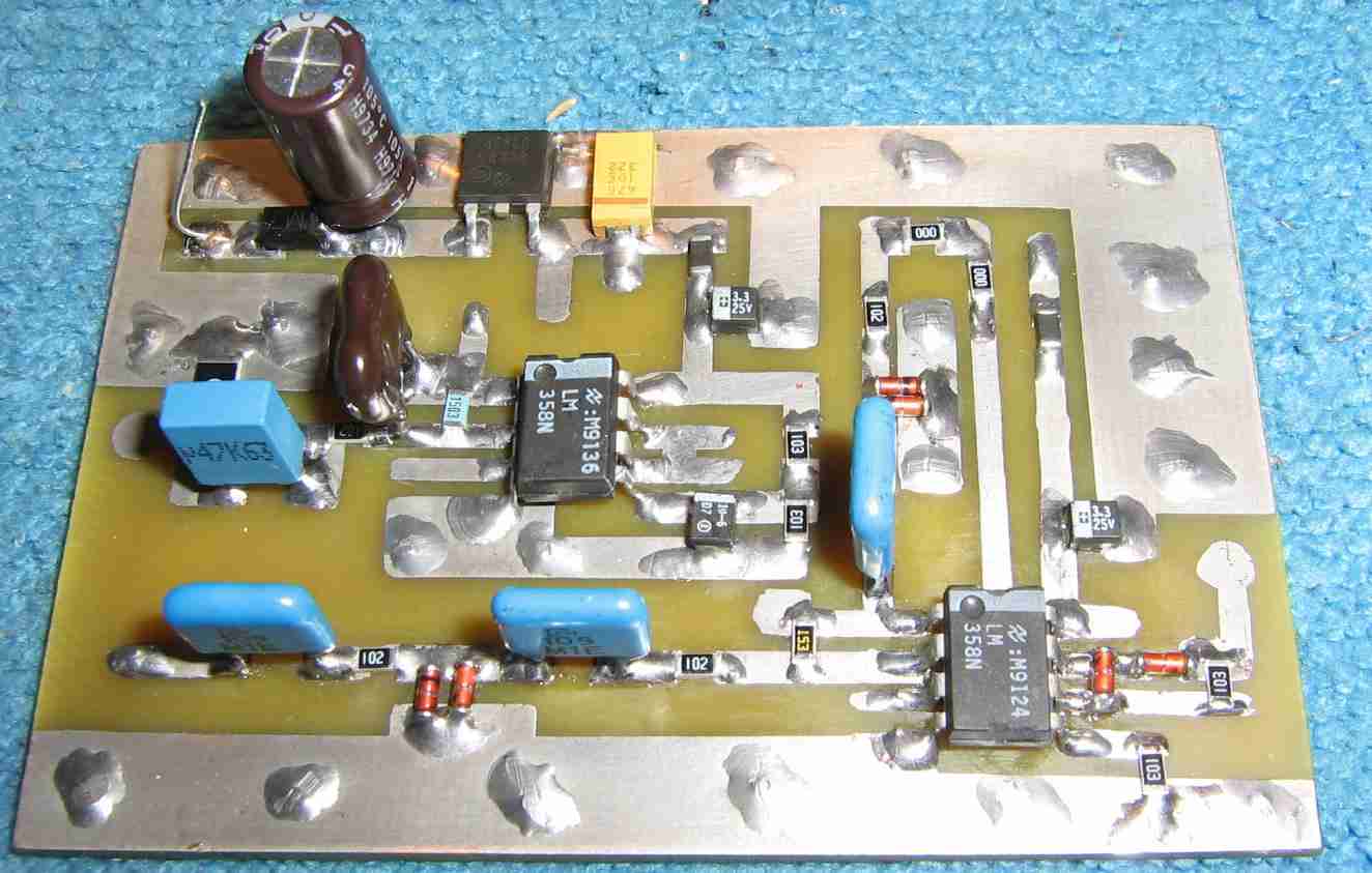
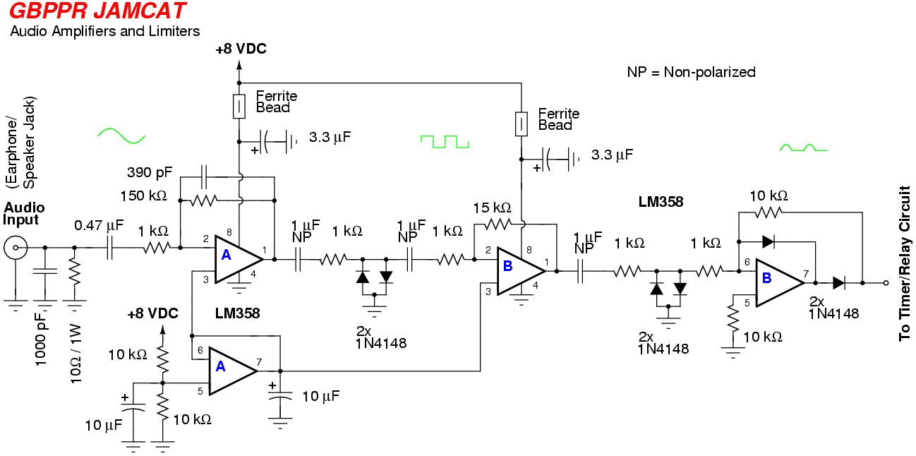
GBPPR JAMCAT Audio Amplifier and Limiter circuit board.

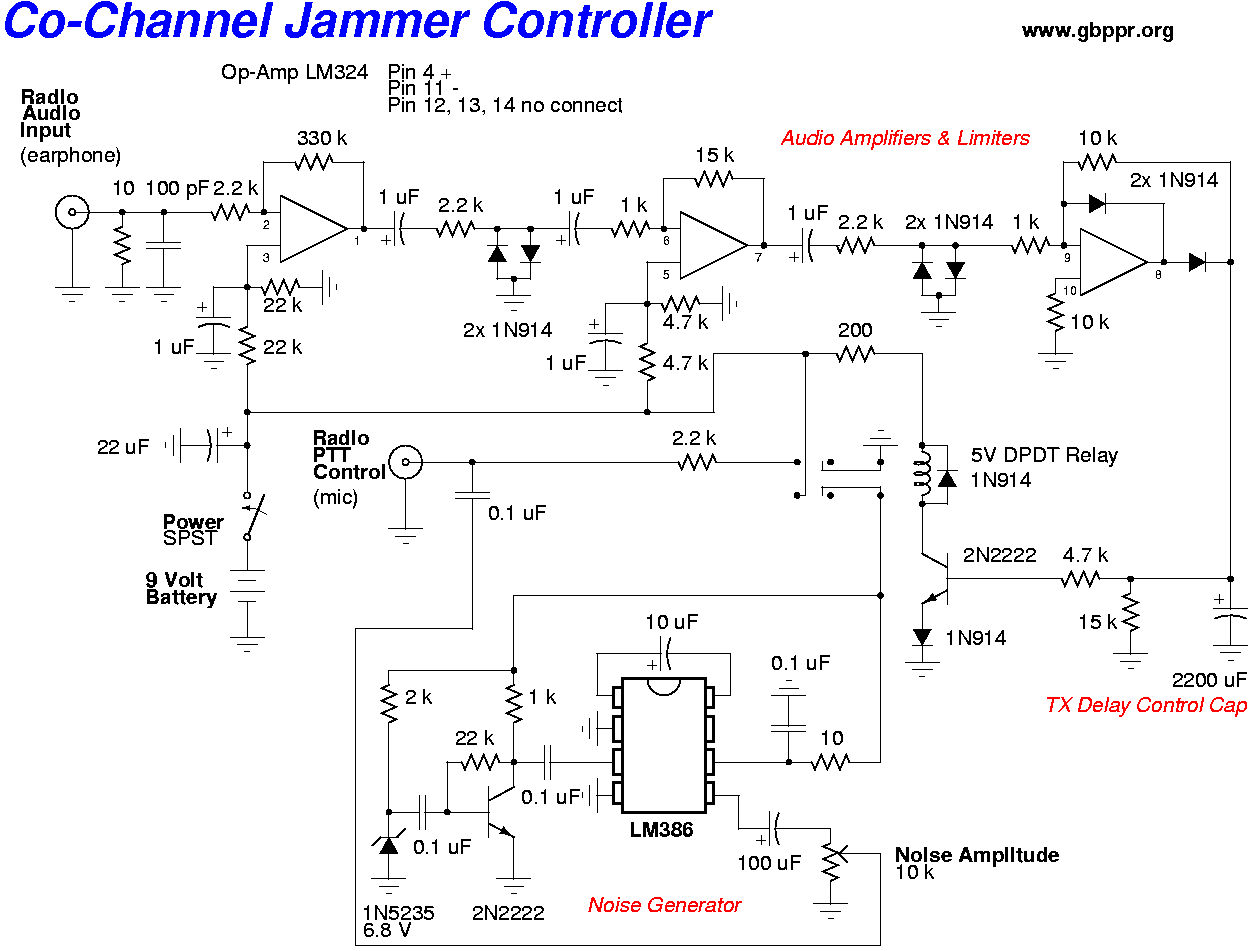
Two LM358 op-amps are used to amplify and limit the input audio signal.

The blue, rounded capacitors are non-polarized 1 µF.

A 1 watt, 10 ohm resistor on the Audio Input acts as a load for the transceiver's speaker output.

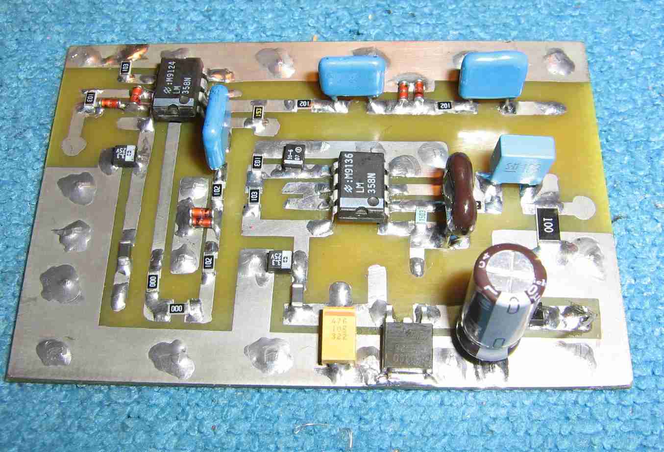
GBPPR JAMCAT Audio Amplifier and Limiter circuit board, alternate overview.

A 78M08 +8 VDC voltage regulator is along the bottom.

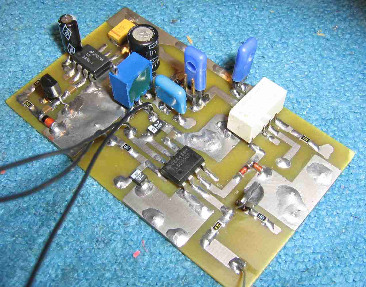
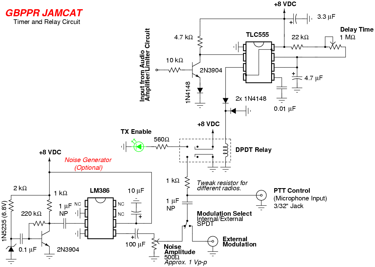
GBPPR JAMCAT Timer and Relay circuit board.

The DPDT relay is the white rectangle device.

The LM386-based noise generator circuit is along the top of the circuit board.  The 1N5235 Zener is the orange/black device.

The blue thing with the screw top is the 500 ohm Noise Amplitude potentiometer.

DIP headers where used for experimenting with different PTT control options and are not necessary in the final circuit.

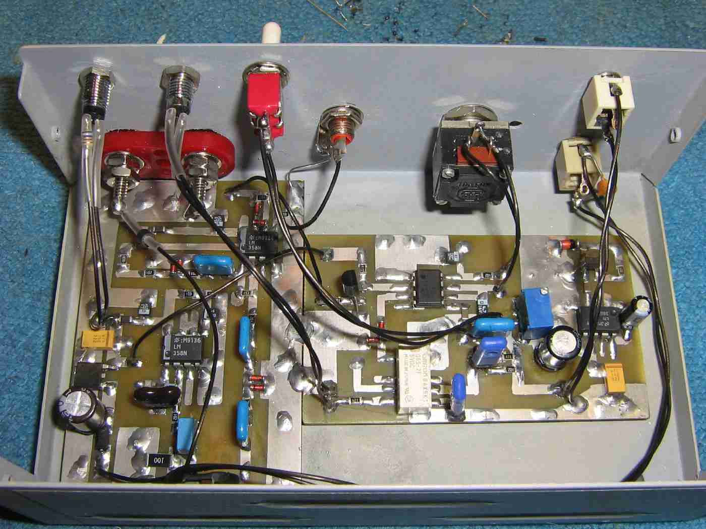
Completed circuit, internal overview.

Mounting the circuit board in an old printer switch case.

+12 VDC power input is via the banana jacks on the upper-left.  A power-indicating red LED and the green TX Enable LED are above it.

The Audio Input and PTT Control inputs are along the upper-right.

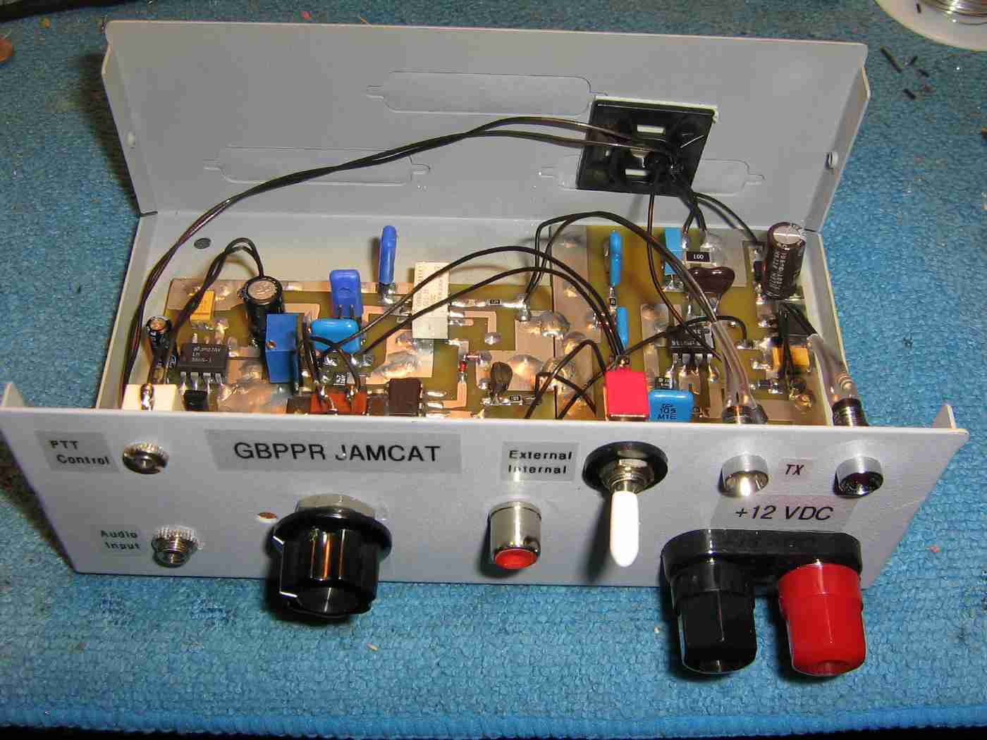
Front-panel overview of the GBPPR JAMCAT.

The green TX Enable and red Power LEDs are panel-mounted on the top-right.

The banana jacks below the LEDs are for the +12 VDC power input.  There is no power switch for this device and the current draw is around 80 mA when activated.

The internal/external Modulation Select switch is to the left of the LEDs.  This selects between the internal noise generator or the option of using an external modulation source via the panel-mounted RCA phono jack.

The 1 megaohm transmit Delay Time potentiometer is in the center.

The 1/8" mono jack for the low-impedance Audio Input is on the lower-left.

The 3/32" mono jack for the PTT Control is on the upper-left.
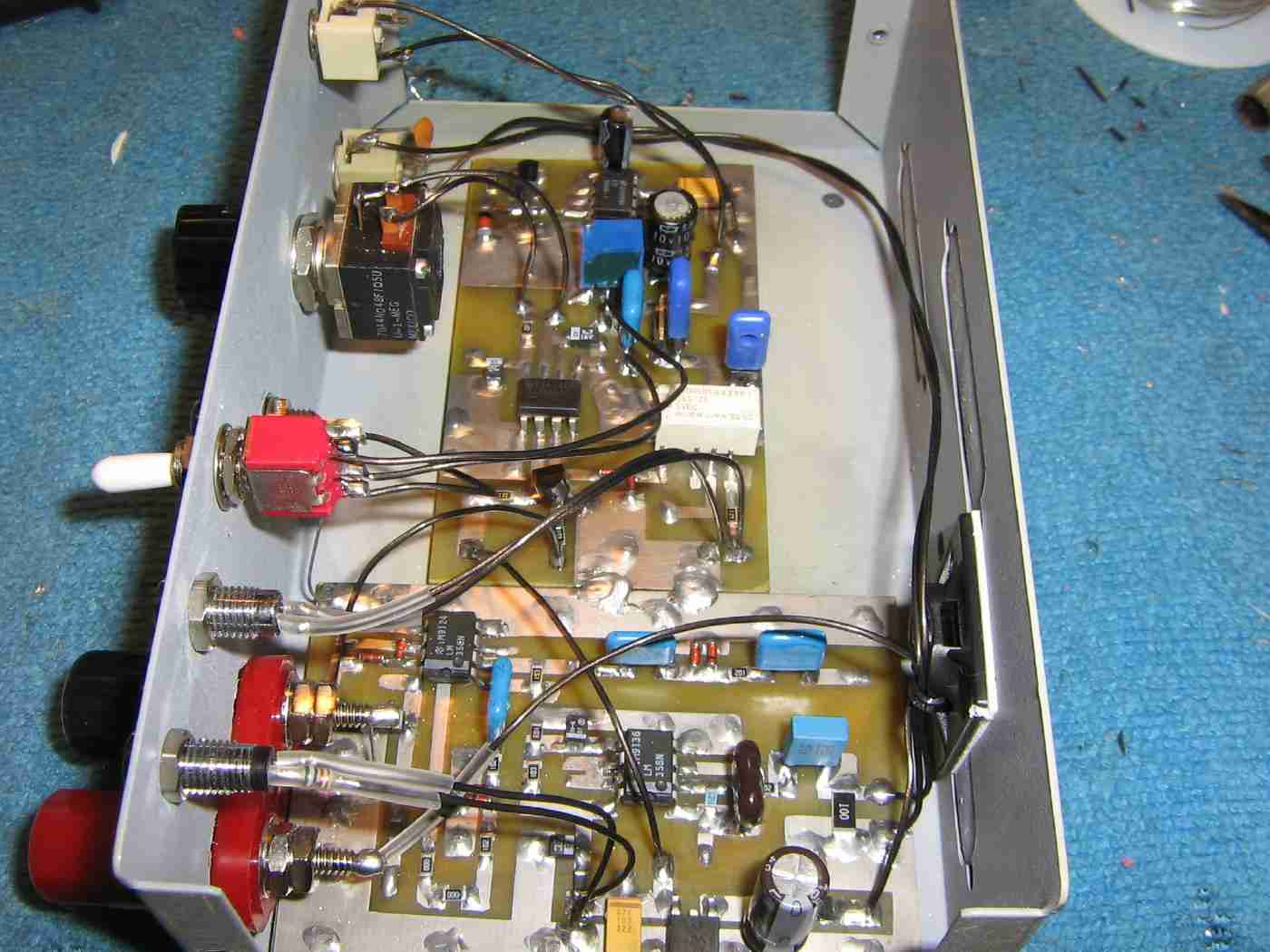
Internal overview.

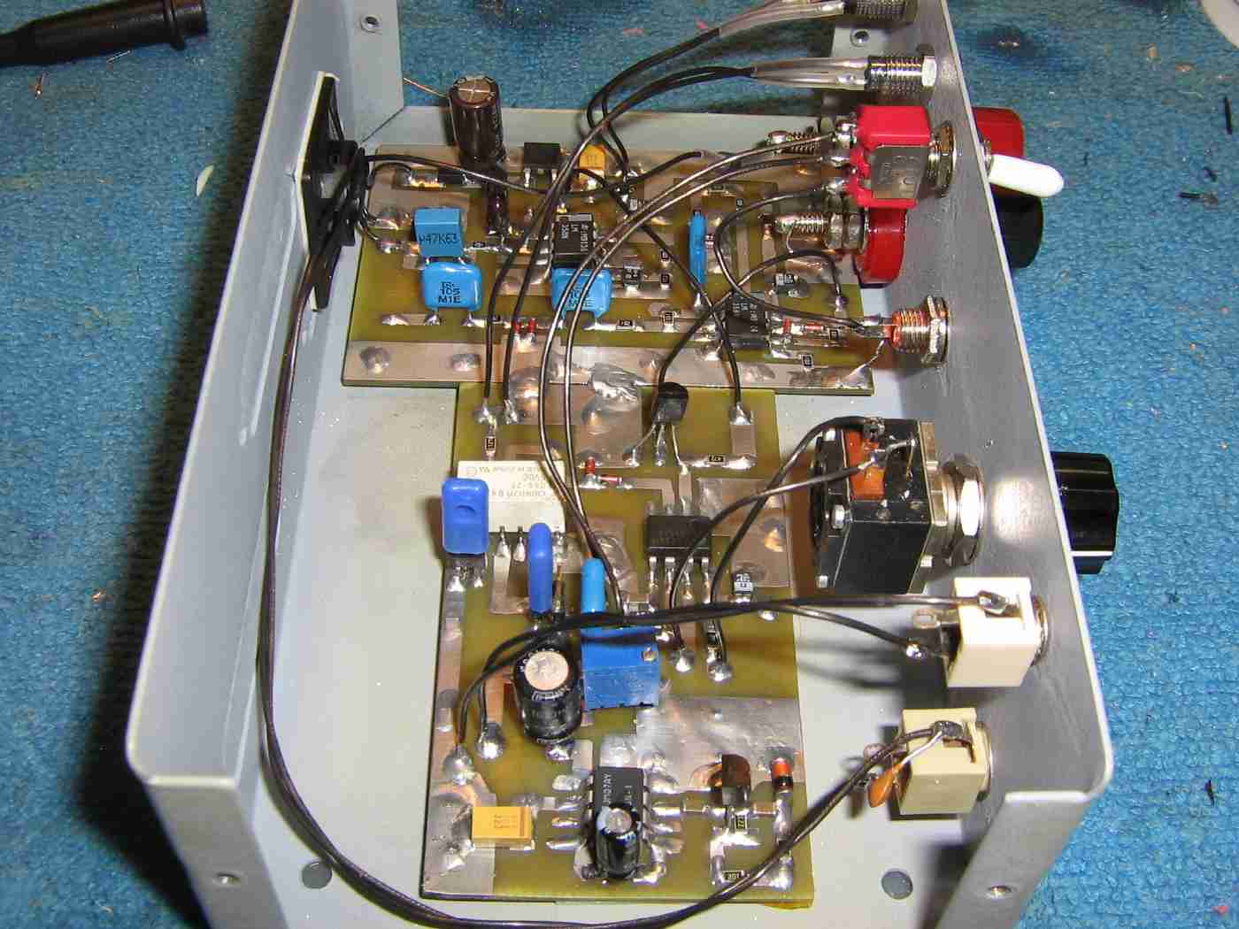
Alternate internal overview.

The 1000 pF capacitor is directly connected to the Audio Input jack.

Keep the lines going to the Delay Time potentiometer as short as possible.

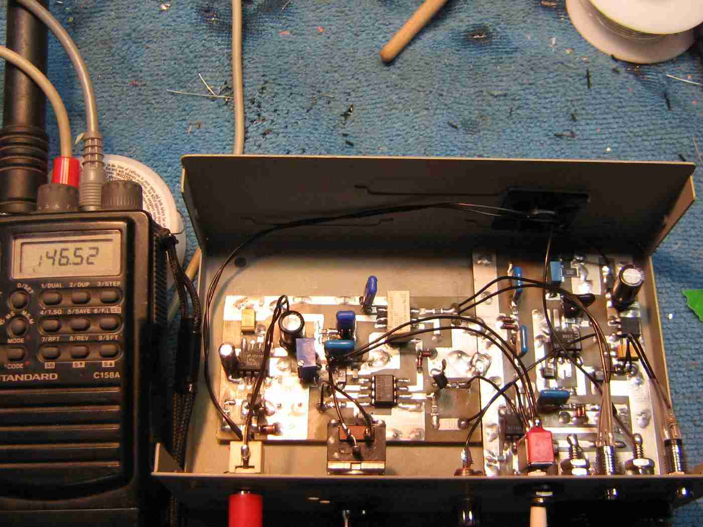
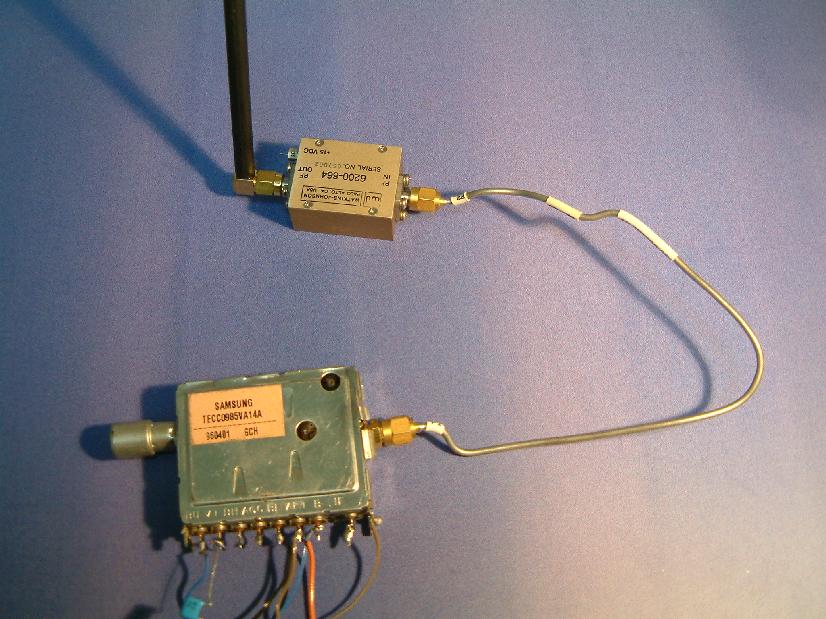
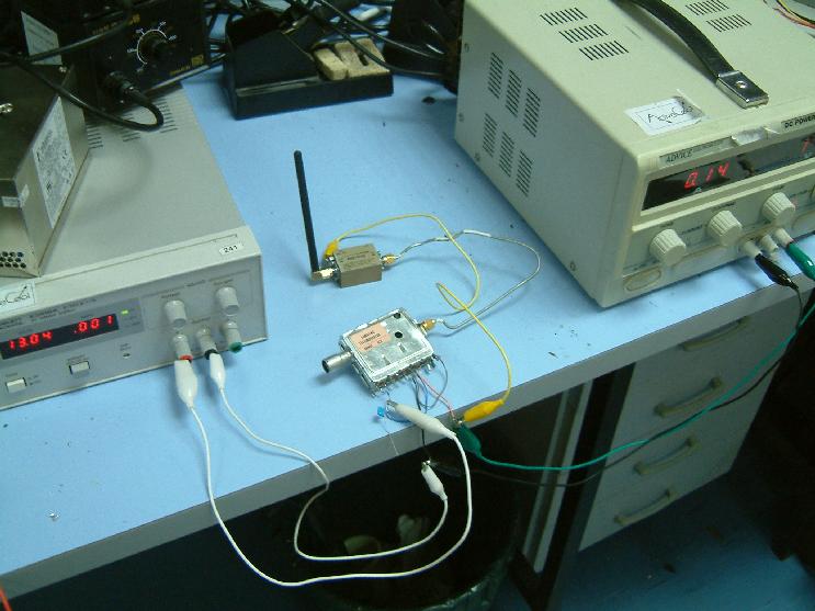
Example jammer setup using the PTT/microphone and earphone/speaker output jacks on a Standard C158A 2-meter amateur radio transceiver.

The Standard C158A's earphone/speaker output is connected to the JAMCAT's Audio Input jack (1/8").

The Standard C158A's PTT/microphone input is connected to the JAMCAT's PTT Control jack (3/32").

This example setup can only jam a single frequency, 146.52 MHz, in this case.

Any detected transmissions on that frequency will cause the C158A to transmit for approximately three seconds, which is controlled via the Delay Time potentiometer.

By using a separate frequency-agile receiver and transmitter, you can "listen" on one frequency and transmit on another!

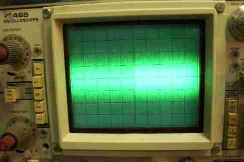
Oscilloscope view of the internal noise generator's output signal.

The oscilloscope's settings are 0.5 V/division (Y) and 10 mS/division (X).

Tune for a noise signal about 1 volt peak-to-peak.

The noise signal's amplitude is adjustable via the 500 ohm Noise Amplitude potentiometer.

The noise generator circuit may break into oscillation or output a very low noise signal.  If it does this, adjust the Zener bias resistor (2 kohm) up or down a few hundred ohms while observing the signal (disconnected from the LM386) on an oscilloscope for the maximum noise signal.  The LM386 can also oscillate without a good ground and poor power supply bypassing.

Any Zener diode above or equal to 6.2 volts will work in the noise generator as these Zener diodes have an "avalanche" region which generates a tremendous amount of noise when properly biased.

Schematic

Tactical Communications Jammer

Very simple barrage (noise) jammer for VHF/UHF communications.  Based around an old TV tuner with its local oscillator signal tapped and amplified.  The tuner's voltage tune line is mixed with a sweeping, random noise signal.

Datasheets & Notes


Return to Homebrew Military & Espionage Electronics Page