Overview
An inductive telephone tap is a device to surreptitiously intercept the audio on an analog telephone line without the need for any direct physical connection. This makes detection fairly difficult.
You'd first locate their telephone line pair within a wiring closet, outside network interface, or in a terminal box somewhere downstream. Next, you'd slip the ferrite pick-up coil over only one of the two wires making up the telephone line pair. It can be either ring or tip, it doesn't matter. The reason you can only use one wire is that a telephone line pair is a balanced transmission line. This means that if the two wires where to pass through the same ferrite core, the out-of-phase signals would cancel each other! Now, due to real-world conditions, telephone lines are not perfectly balanced, but always try for a proper pick-up connection.
Wait for them to use the phone. When they do, the audio should be crystal clear. The GBPPR Telephone Induction Tap uses proper pick-up coil impedance matching and low and high pass filters to remove any static or hum from the audio signal.
Circuit Operation
This induction tap circuit varies dramatically from other common designs which appear on the Internet. The first major change is that the split-core ferrite pick-up coil is designed for an approximate 8 ohms impedance (@ 1 kHz). This is done by wrapping one side of the split-core ferrite with enameled 30-gauge magnet wire (Radio Shack part # 278-1345) until the inductance value measures approximately 1.3 µH. Try to keep the wrapped wire "flush" with the inside of the ferrite core. If you don't have an inductance meter, try just wrapping about 100 turns or so. The exact model of the split-core ferrite can be quite critical. All Electronics, http://www.allelectronics.com, carries several varities of "ferrite split beads with snap sleeves." Part numbers FB-53 or FB-48 look like they could work and those "suction cup" pick-up coils will work in a pinch. The ferrite pick-up core's output is wired as a balanced connection. You'll need to use a shielded two-line wire to connect it back to the audio preamplifier. Balanced microphone wire works wonderfully. Only connect the wire's shield to ground on the audio preamplifier side.
Next, that signal is fed into a 8 ohm to 1,000 ohm impedance matching transformer. This is designed to "step-up" the low-impedance of the pick-up coil for better matching to the first LM833 op-amp in the low-noise preamplifier circuit. Surprisingly, that impedance matching transformer is available from Radio Shack, part # 273-1380. The transformer's RED and WHITE wires are on the the "8 ohm" side and the GREEN and BLUE wires form the "1,000 ohm" side. The BLACK center tap wire is not used and should be cut off. The second op-amp of the LM833 is wired as a DC bias generator. This allows the LM833 to operate without the need for a negative voltage, which can add excess switching noise. A 100 kohm potentiometer controls the gain of the LM833, up to around 40 dB. The 220 pF capacitor rolls-off the LM833's high-frequency response.
After amplification, the signal is sent through a simple high-pass filter consisting of a series 0.1 µF cap and shunt 5.6 kohm resistor. The signal is then sent to a Maxim MAX295 8th-order, low-pass switched capacitor filter. The MAX295 is wired as a variable cut-off, low-pass filter with a maximum frequency of approximately 6 kHz. The MAX295 also naturally attenuates any 50/60 Hz induced hum. The MAX295's output routes through a 10 kHz low-pass filter to attenuate any high-frequency clock noise. A CMOS 555-timer (Radio Shack part # 276-1718) generates the MAX295's needed clock signals. The 555-timer should be CMOS for the best and most stable performance. A 10 kohm potentiometer controls the frequency of the 555's clock signals. They'll vary from about 30 kHz to up around 500 kHz. This corresponds to a variable low-pass frequency cut-off in the MAX295 from around 600 Hz to 10 kHz. Fiddle with the 555's 1000 pF timing capacitor to change the clock frequency.
The signal is then fed to a TL071 op-amp configured as a 300 Hz high-pass filter. This further attenuates any 50/60 Hz hum and any other low-frequency rumbles.
Finally, the signal is fed to a LM386 audio amplifier (Radio Shack part # 276-1731). The LM386 is only designed to drive low-impedance (8, 16 or 32 ohm) headphones or speakers. The 10 µF capacitor across pins 1 & 8 of the LM386 is not needed if you only use headphones. To connect the audio output to a tape recoder, get another 8 ohm to 1,000 ohm impedance matching transformer and wire the 8 ohm side to the LM386's audio output and the 1,000 ohm side to the tape recorder input. Or tap the wiper of the 10 kohm volume pot directly, if you're so inclined.
Power is provided via a standard 9 volt battery. +5 VDC regulation is taken through a 78L05. -5 VDC is generated via a Maxim MAX660 voltage inverter. The MAX660 can source a higher output current and has a higher switching frequency, which is useful for this circuit.
Try to use 1% tolerance, metal-film resistors throughout the circuit. They offer the highest stability and lowest noise. Audio coupling capacitors and capacitors in the filters should be of film (polystyrene, mylar, etc.) dielectric. These are the "quietest" as they are not microphonic. Build the entire circuit into a metal box and always use a new, fresh 9 volt alkaline battery. Twist the wire leads from the potentiometers and audio output to reduce noise pick-up. Use a printed circuit board with a large ground plane and try to keep the input and outputs separated to avoid feedback oscillations.
Detecting an Inductive Phone Tap
Yes, you can detect an inductive phone tap. Physical inspection is always the best, but a device called a Time Domain Reflectometer (TDR) can also be used. This is a device which sends a series of fast-rising (picosecond) pulses down a wire, then monitors their reflection on an oscilloscope. Sort of like a hard-wired radar. Since the ferrite pick-up core is an inductor, the returned signal will be distorted, as some of the energy of the transmitted pulse is "absorbed" into the ferrite. To counter a TDR, place the tap after a loading coil placed on the telephone wire pair or use a very small ferrite pick-up core. Also, you can place a tone (milliwatt, tone sweep generator, etc.) on your telephone line and probe around the terminal box looking for the tone to show up on another pair or any other suspicious wires. If you were to call your local milliwatt plant test number and you heard that 1,004 Hz tone while scanning the airwaves with your Radio Shack scanner... well... that wouldn't be good.
Pictures
Examples of split-core ferrites. Center ferrite shows the necessary winding of the 30-gauge enameled wire. It measures approximately 1.3 µH.
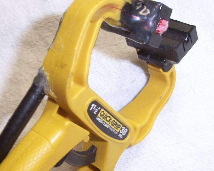
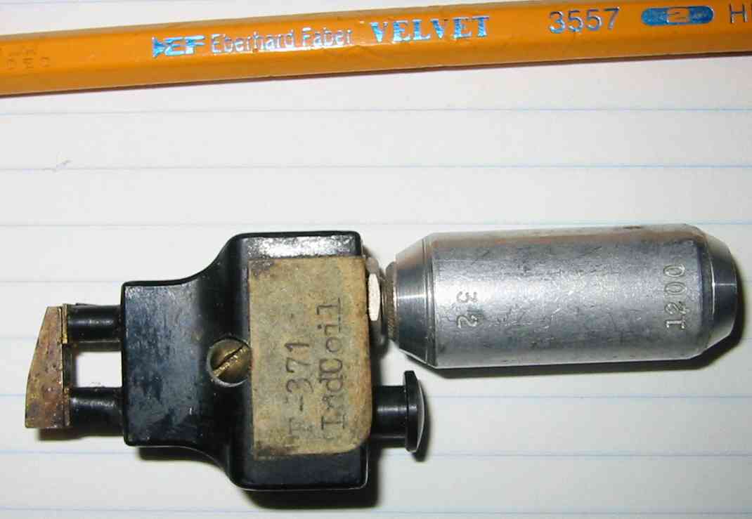
Test version. Each side of the ferrite core is epoxied to an arm of an adjustable clamp. The wiring routes along the sides of the clamp to a RCA jack.
Working version. The RCA jack was replaced with a piece of microphone wire connected to a 1/4-inch stereo plug. The 30-gauge windings go to the ring and tip of the 1/4-inch plug and the shield to the sleeve.
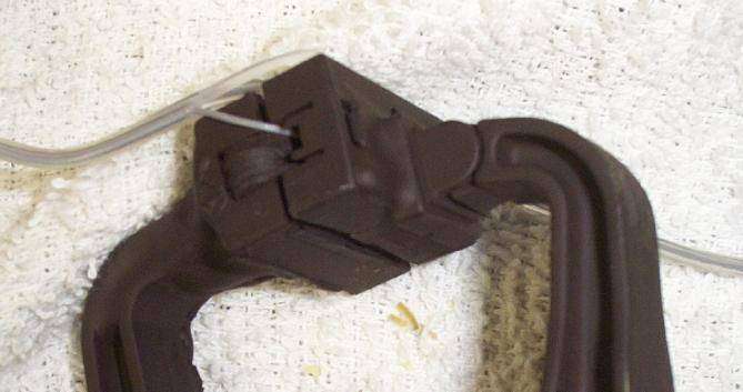
Closeup picture. Several layers of epoxy are used to build up and protect the wiring. The top ferrite core is epoxied directly to the clamp's arm, so it can't move.
Top, side view. Note the 30-gauge wire embedded in the epoxy.
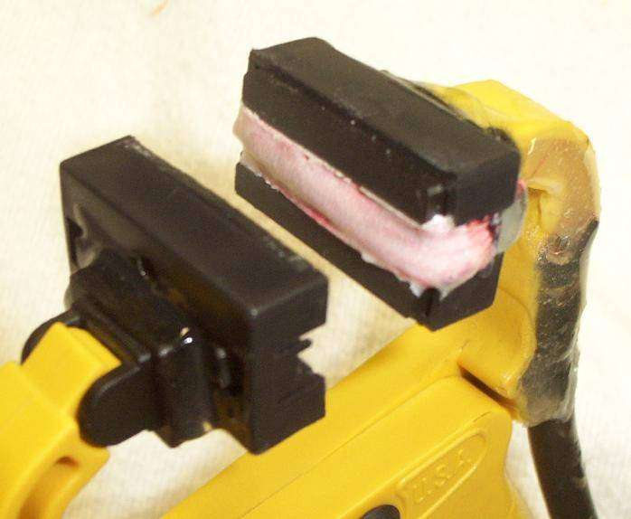
Closeup picture of the ferrite cores. The one on the left is adjustable, the one on the right is fixed. The white stuff on the 30-gauge wiring is Q-Dope to secure and protect the enameled wire.
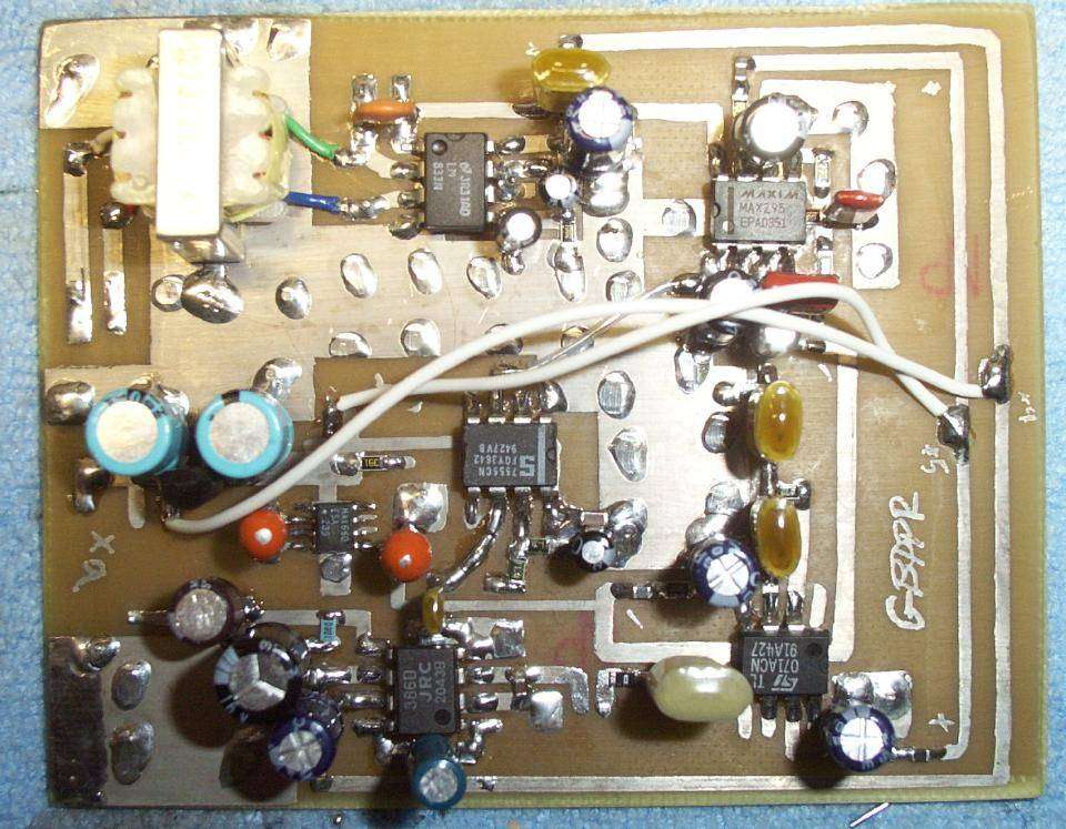
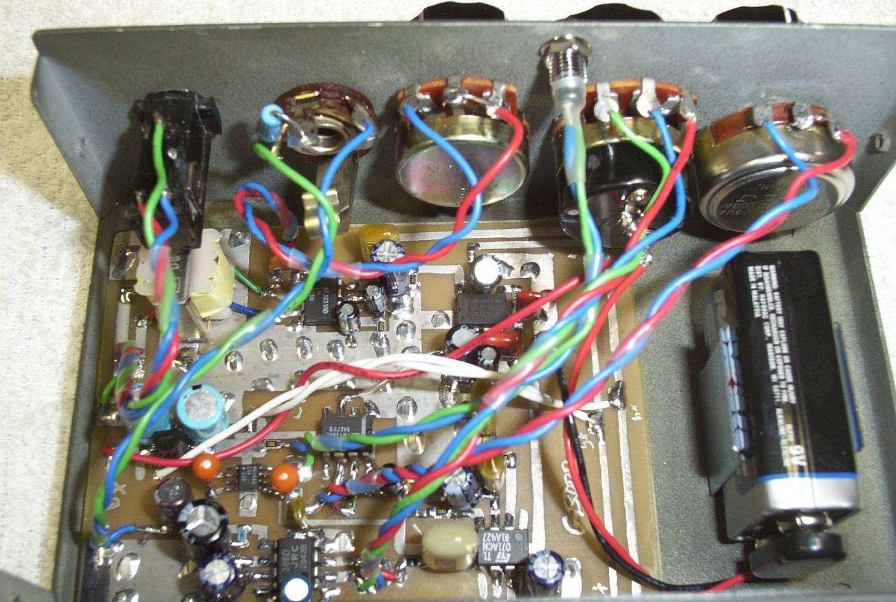
Picture of the audio amplifer and filtering board. The impedance matching transformer is on the upper left, LM833 is to the right of the transformer. The MAX295 is then to the right of the LM833. Below the MAX295 is the TL071 op-amp. The large, yellow capacitors are polystyrene. To the left of the TL071 is the LM386. Above the LM386 is the CMOS 555-timer. The little IC to the left of the 555 is the MAX660. Inbetween the two blue electrolytic caps is the 78L05.
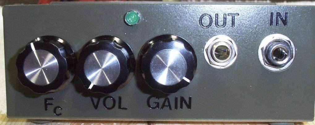
Front panel overview. It's an old printer switch case and is a tad too small, but works. Fc is the MAX295 frequency cut-off control, VOL is the volume control with an integrated on/off power switch, GAIN is the LM833's gain control pot. OUT is a 1/4-inch mono jack and IN is a 1/4-inch stereo jack. I have no idea what the green thing that looks like an LED is.
Internal view with everything connected. Use double-sided foam tape to mount the PC board. The normally closed contact on the 1/4-inch output jack has a 100 ohm resistor wired to ground. This prevents any circuit oscillation in case headphones are not connected while powered. Twist the wires to reduce noise pickup.
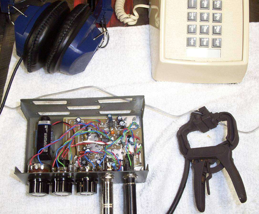
Test setup.
Test setup pick-up connection. Only one wire of the telephone line pair passes through the ferrite core. The adjustable clamp was spray painted for camoflauge.
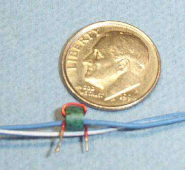
Yes Sparky... they get even smaller.
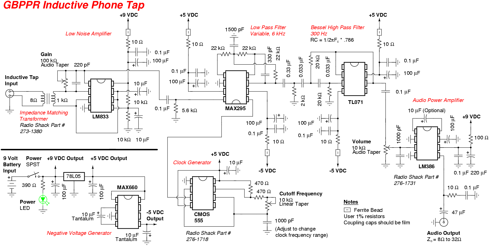
Schematic
Notes & Links