15 February 2000. Thanks to anonymous for pointing.
Source: Hardcopy Abacus, Vol. 5, No. 2, Winter 1988, pp. 10-18, 53.
Copies of the Swedish 1982 technical weekly and 1984 booklet on electromagnetic
eavesdropping cited here would be appreciated.
An English translation even more so. E-mail:
jy@cryptome.org
For comprehensive information on Tempest see The Complete, Unofficial TEMPEST
Information Page:
http://www.eskimo.com/~joelm/tempest.html
The Tempest over Leaking Computers
by Harold Joseph Highland
Harold Joseph Highland is Distinguished Teaching Professor Emeritus
of the State University of New York and a Fellow of the Irish Computing Society.
He is editor-in-chief of Computers & Security, the official journal
of IFIP Technical Committee 11. As managing director of CompuLit Inc., he
heads the organization's Microcomputer Security Testing Laboratory. He writes
regularly for several computer and law journals in England, Germany, Australia,
Italy, and the States. He was Fulbright Professor of Computer Science at
Helsinki University of Technology and the Medical School of the University
of Helsinki in 1970-1971. He is the author of over 200 technical articles
and some 30 books several of which have been translated into Japanese, German,
French, Dutch, Finnish, and Russian. He received his Ph.D. in 1942 B.C. (before
computing) while serving with the USAAF during World War II, and learned
computing by a "hands-on-approach" while he was dean of the Graduate Business
School at Long Island University in 1958.
In the spring of 1985 the British public viewed the first demonstration of
eavesdropping on a computer's electromagnetic radiation. BBC's "Tomorrow's
World" ran a five-minute demonstration on television. The program showed
a long shot of a van parked in front of a building in London and faded to
a close-up inside the van where a document was displayed on a television
screen. The commentator noted that the van's equipment had to scan numerous
terminals and documents inside the building before finding one on the upper
floors that was suitable to show on the air. At no time did the program identify
the building because it is as well known in England as the U.S. Capitol is
in the States. The London building in front of which the van was parked was
New Scotland Yard.
Anyone can put together a primitive eavesdropping unit for somewhat over
$100. All you need is a portable television set with a voltage-controlled
oscillator (VCO) tuner (one with no detents or stops between the channels
and no fine tuning control), a dipole antenna with a 75-ohm balum (a balance
transformer to match the impedence of the antenna with that of a television
set's cable), and a 75-ohm coaxial cable to connect the set to the antenna's
balum. The unit will have a limited range, between 20 and 40 feet, and the
reception may be poor because the picture will be unsteady. If extensions
are used with the vertical and horizontal hold controls for finer tuning,
picture quality will improve. With some knowledge of television design and
construction, you could built a more efficient unit at higher cost. The circuit
diagram of a TV set with a VCO tuner is available in Sams Photofact #2218,
a series used by many television repair shops.
The current widespread interest and dismay over electromagnetic radiation
(EMR) and electromagnetic eavesdropping might suggest that these are now
phenomena or at least were recently discovered. Neither is true. For more
than twenty years, international military and intelligence agencies have
known that all electronic equipment without suitable shielding generates
high levels of radio frequency (RF) signals that can be intercepted and
reconstituted into intelligible information.
The interception and reconstitution of radiated signals, remained a concern
basically of the military and intelligence communities until March 1985,
when a Dutch engineer, Wim van Eck, demonstrated passive electromagnetic
eavesdropping equipment at Securicom '85 in Cannes, France. In his presentation,
van Eck explained that one could produce an eavesdropping device capable
of reading data from the screens of terminals and monitors easily at low
cost. Checking the materials used against a Radio Shack catalog, he reported
a cost of about US $75. In addition to his device, a variable oscillator
and frequency divider, he used a television set and a tunable antenna, which
added about another $150 to his costs. (see Figure 1).
| Are you sharing confidential data with people who are not particularly
close to you?
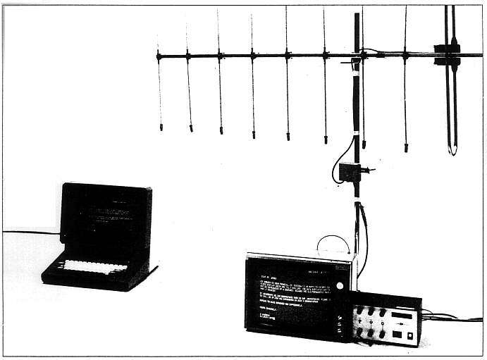
Figure 1. Laboratory view of the van Eck eavesdropping equipment during
system calibration (from left to right): [a] a VDT unit which can be up to
1 km away from the eavesdropping device, [b] a television set used to reproduce
the VDT's screen, [c] a UHF array antenna with a 75-ohm balum (a transformer
to match the 300-ohm transmission line from the antenna to the 75-ohm impedence
level of the television receiver), [d] a 75-ohm coaxial cable to connect
the antenna's balum to the television set, and [e] the variable oscillator
and frequency divider to restore synchronization; it is connected to the
television set. (Photograph courtesy of the Dutch PTT Dr. Neher Laboratories.) |
Tempest Control of
Compromising Emanations
Tempest standards are classified and are provided only a need-to-know basis
to organizations involved in producing such equipment. Some information has
been leaked to the technical press so that some techniques are known but
have not been officially acknowledged. The accompanying diagram illustrates
some of the techniques used to protect a VDT and keyboard.
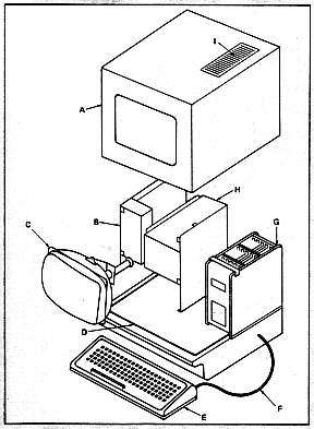
A In place of the conventional plastic housing, a metal case is used
for both the VDT and the keyboard. The parts of the housing are made so that
there is an overlap of metal at each seam and the seams are welded together
with no gaps. A braided metal wire ground is secured to an unpainted surface
of the metal base.
B The main power supply switch, fuse, and electrical RF filter are
enclosed in a metal box that is grounded to a paint-free surface.
C A flexible EMI gasket is fitted around the face of the CRT to seal
the opening when the cover is in place. The CRT anode, the screen. would
be metal coated, preferably gold, and the face of the CRT is covered with
a metal-coated mesh with an antireflection coating.
D An EMI gasket is placed in a groove in the metal base of the unit
into which the top housing fits securely.
E The keyboard in its metal housing is surrounded by an EMI gasket,
and the keys are coated with a metallic vapor or covered with a formed
metal-coated film.
F A shielded cable connects the keyboard to the VDT.
G Any printed circuit boards used within the VDT are encased in a
metal cage grounded to the metal base. The more security-sensitive boards
are placed away from the outside of the unit. The cable connectors are grounded
against the board cage and not the base of the unit.
H The high voltage supply needed by the CRT is shielded in a metal
unit and grounded to the base unit.
I Ventilation is provided by louvered slits in the top or back of
the unit with an EMI underscreen or special honeycomb unit. |
What startled the audience at the conference was the device's ability to
read visual display terminal (VDT) data from outside a building. Wan Eck
noted that with slightly more sophisticated and expensive equipment, it was
possible to intercept data from a VDT screen up to l kilometer away.
Several hundred computer security specialists, mostly from Europe, attended
Securicom '85. French law prohibits public discussions of electromagnetic
radiation eavesdropping. As a result, the conference director decided to
have no French citizen involved with the van Eck presentation: I chaired
the session. During the question-and-answer period following van Eck's
presentation, an attendee told the audience that only a few months earlier,
in October 1984, the West German police had apprehended a Polish spy. The
police found among his papers a list of excellent locations for using electronic
eavesdropping equipment to obtain information from various government and
industry computers.
The European press at the conference interviewed Wim van Eck and me extensively.
Within a week over 700) articles appeared in newspapers all over Europe.
Lost in the stories about the "Van Eck phenomenon" were the reasons Wim van
Eck undertook his project. The Dutch PTT (Post, Telephone, and Telegraph,
operates both the telephone service and mail delivery and prefers to transmit
mail electronically instead of physically, so it has tested monitors and
keyboards connected to telephone lines in homes for sending and receiving
mail.
During the tests the Dutch PTT found that some users complained about
interference from their neighbor's units. Several persons were able to read
a neighbor's mail as the neighbor viewed electronic mail on the screen at
home. Van Eck's section in the PTT was assigned the task of developing an
inexpensive detection unit to monitor RF electromagnetic radiation. This
unit would be used to evaluate monitors for the home and could be used in
the field to help with installation problems.
A few articles were published in the U.S. but many computer professionals,
security specialists, and business people are still unaware of the danger
of electro magnetic eavesdropping and the countermeasures that can be taken.
Tempest and Government Relations
The U.S. government appears willing to go to embarrassing lengths to keep
an open discussion and demonstration of electronic eavesdropping equipment
from the public -- even the technical and professional personnel not directly
involved in its countermeasure program.
The Tempest (Transient ElectroMagnetic Pulse
Emanation STandard) project is a joint research and development
effort of the U.S. National Security Agency (NSA) and the Department of Defense
(DoD) and has been classified for about 20 years. Even the program's name
was classified and unmentionable until only a few years ago. Tempest refers
to the investigation and study of potentially compromising electronic signals
emitted by computers and other electronic devices. It also involves the
development of countermeasures, particularly the shielding of computers and
related devices so that the emanations cannot be collected, analyzed, and
understood.
A national Tempest policy was embodied in the National Communications Security
Committee Directive 4, "National Policy on Control of Compromising Emanations,
issued in January 1981. It instructed all federal agencies to protect classified
information against compromising emanations. The procedures to use in determining
the countermeasures needed for equipment and facilities were specified in
the National Communications Security Instruction 5004, which was issued in
January 1984 and classified as secret.
Production and testing of NSA's Tempest-shielded equipment is big business.
About 175 companies are authorized to produce or test Tempest-shielded equipment.
Frost & Sullivan, a New York research company, predicts that sales of
Tempest security systems and services will rise from $874 million in 1986
to $2.9 billion in 1992. Most of these sales will be made to the intelligence
community, the military, law-enforcement agencies, and some civilian federal
government agencies. The survey notes the important role that NSA is playing
in the promotion of Tempest technology and the growth in classified military
research created by larger defense budgets.
In the United States neither NSA nor DoD has been willing to provide any
information to the national press, or even the technical press. In fact,
open discussion of this topic has been barred at professional meetings.
At the annual computer security conference and exhibition of the Computer
Security Institute (CSI), a private organization, in November 1986, government
intervention was evident. In one case an exhibitor interested in demonstrating
the effectiveness of his product against electromagnetic eavesdropping withdrew
before the conference opened. In another case, Wang Research Laboratories
(Wang is the largest producer of Tempest equipment) had agreed to give a
demonstration of eavesdropping equipment to computer security specialists.
NSA stepped in and formally classified the speech the Wang speakers had intended
to make. At the Interface '87 conference, a major Washington, DC, company
canceled its seminar, "How Computer Security Can Be Compromised," a demonstration
of passive eavesdropping techniques, at the request of the NSA.
The Swedish Approach
The Swedish government's approach to the problem is different. The danger
of electromagnetic eavesdropping was exposed by a Swedish technical weekly
late in 1982. By early 1983 National Police Board specialists began informing
security specialists and directors in the business community about radiant
signals (ROS in its abbreviated form in Swedish), including superimposed
signals in power networks and acoustical signals.
In 1984 the Swedish Government Commission on the Vulnerability of EDP Equipment
and the National Council for Crime Prevention jointly issued an 18-page booklet
entitled Läckande Datorer ("leaking computers")[See
reference]. The booklet provides information
about the problem and includes instructions regarding countermeasures aside
from Tempest-shielded equipment. A table indicates how, in principle, five
types of measures protect or do not protect against four types of radiant
signals. The booklet became a best-seller in the business community and is
still in print.
Aside from acoustical signals, the booklet reveals three critical forms of
electronic radiation:
-
V-RR or video signal radiation, the area in which van Eck worked .
-
R-RR or radio component radiation, all the remaining signal frequency radiation
generated by computer equipment and networks as a side effect of internal
currents and voltage leakage.
-
L-RR or electrical line radiation, the direct electrical effect on other
legitimate currents, primarily the power modulation of the electrical lines
even at the electrical outlets.
Electromagnetic Leakage
Anyone with some knowledge of elementary physics is aware that electricity
flowing through a wire propagates an electromagnetic wave (see Figure 2).
Electromagnetic interference (EMI) is any form of electrical disturbance,
signal, or noise, a common phenomenon that crosses all electric and electronic
disciplines. EMI problems appear in all degrees, from a nuisance to catastrophic
accidents.
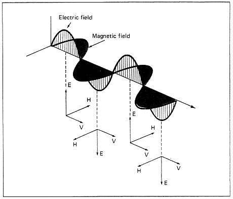
Figure 2. Electricity flowing through a wire or any electronic component
propagates an electromagnetic wave with two vectors, the electric vector,
E, and the magnetic vector, H. V is the direction of
wave travel. These waves are generated by the components and printed circuits
within a VDT and/or a microcomputer. Relative radiation levels of some of
the popular logic families include a 0.1 mA current in a CMOS (complementary
metal oxide silicon) with a bandwidth of 3 MHz to a 30 mA current in an S-TTL
(transistor to transistor logic) with a bandwidth of 120 MHz. |
In one instance, radio-controlled automatic garage doors mysteriously failed
to work in one part of the U.S., but only on certain days. After some electronic
sleuthing, it was found that the scrambled communications signals transmitted
by satellite to the President's E4-B command plane parked at March Air Force
Base interfered with the garage-door opener signals in the area.
In another instance, an operator using a handheld radio for in-plant
communications caused a ladle of molten steel moving along an overhead crane
to tip and splash nearby workers. He was about 15 feet away from the drop
cable with its six-pushbutton control box that was used to control the crane's
movement and operation.
Computer dinosaurs like myself remember the early days in computing when
terminals were introduced. We found that a terminal in one room interfered
with another terminal along the same wall in the next room. In one instance
in a hospital we found that screens were wiped clean when a fluoroscope two
floors above was used.
The Federal Communications Commission (FCC) has attempted to control the
EMI problem in order to eliminate interference with radio and television
reception. Only a few years ago, people who lived near operators of ham equipment
found interference with their TV and even radio reception. Some still do.
In 1984 the FCC started to require microcomputer manufacturers to make certain
that the units did not interfere with radio-television frequencies. Micros
must be certified as noninterfering before they can sold. Despite this
precaution, the FCC received about 1,000 complaints last year where interference
was traced to microcomputers.
Electromagnetic Emanations from a Computer
Every component of a computer -- the power supply, microprocessor chips,
connecting cables, video display unit, printers, keyboards, etc. -- radiates
RF signals. In designing his eavesdropping device, van Eck attacked the most
vulnerable unit, the terminal or monitor, the visual display terminal.
A VDT radiates a field with two distinguishable parts: [1] narrowband harmonies
of the digital clock signals, and [2] broadband harmonies of the various
random digital signals, such as the video signal. Unlike other broadband
signals inside the VDT, the video signal is amplified before it is fed into
the cathode ray tube (CRT). The screen image is built by means of an electron
beam in a cathode ray tube (see Figure 3). When a high voltage is applied
between a heated electrode (negatively charged cathode) and the conductive
layer on the inside of the screen (positively charged anode), electrons start
flowing from the cathode to anode. The signal required to modulate the light
intensity of the moving spot on the screen is called the video signal.
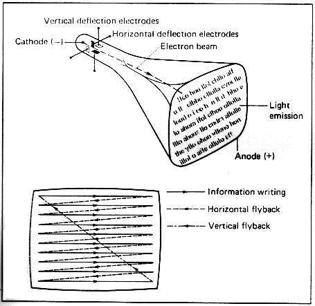
Figure 3. Most easily captured by the van Eck type eavesdropping equipment
are the waves generated by the electrons bombarding the CRT's anode faceplace.
The CRT acts as a miniature television transmitter emitting signals in the
UHF range. The picture on the screen is built up sequentially. Each picture
consists of a number of horizontal lines with the first line at the top and
the last line at the bottom. The screen is refreshed by the electron beam
projected within the CRT, which, when finished with the last line, returns
to the start of the top line and repeats its writing on the screen. |
The acceleration of electric charges results in the generation of an
electromagnetic field. The electromagnetic spectrum is shown in Figure 4.
VDTs are designed to produce visible radiation. but in the process they produce
other types of electromagnetic radiation as well. Hard X rays, gamma rays,
and microwaves are not emitted by VDTs, but soft X rays, ultraviolet, visible,
and infrared light, and various radio frequencies are emitted along with
pulsated radiation, very low frequency (VLF) waves, and extremely low frequency
(ELF) waves.
|
The Electromagnetic Spectrum |
|
Frequency |
Wavelength |
Radiation |
|
1023
1022
1021
1020
1019
1018
1017
1016
1015
1014
1013
1012
1011
1010
109
108
107
106
105
104
103
102
10
1
0 |
3 x 10-15
3 x 10-14
3 x 10-13
3 x 10-12
3 x 10-11
3 x 10⁻¹⁰
3 x 10⁻⁹
3 x 10⁻⁸
3 x 10⁻⁷
3 x 10⁻⁶
3 x 10⁻⁵
3 x 10⁻⁴
3 x 10⁻³
3 x 10⁻²
3 x 10⁻¹
3
3 x 101
3 x 10²
3 x 10³
3 x 10⁴
3 x 10⁵
3 x 10⁶
3 x 10⁷
3 x 10⁸
Infinity |
Cosmic photons
Gamma rays
Gamma rays and X rays
X rays
Soft X rays
X rays and ultraviolet rays
Ultraviolet rays
Ultraviolet rays
Visible spectrum
Infrared rays
Infrared rays
Far-infrared rays
Microwaves
Microwaves and radar
Radar
Television and FM radio
Shortwave radio
AM radio
Longwave radio
Induction heating
Electronic devices
Electrical current, rotating machinery
Electrical current, rotating machinery
Commutated direct current
Direct current, batteries |
Figure 4 |
The electromagnetic radiation emitted hy a VDT that is easiest to capture
is in the television frequency range. The frequency at which a VDT radiates
is almost as unique as a fingerprint. Two identical models from the same
VDT manufacturer usually emit signals at slightly different frequencies so
that a sensitive intercept unit can discriminate between them. In addition,
because of power differences between VDTs in the U.S. and Europe, emissions
are in a different frequency range. Most U.S. units emit a strong UHF signal
between 70 and 94 MHz.
The distance of the VDT from the eavesdropping unit is not the only determinant
of whether or not the signals can be captured and reconstituted. A strong
local TV broadcast signal can mask the VDT signal. Moving the TV receiver
to another nearby location, where the local TV station is weaker, could make
picking up the VDT's signal easier.
The van Eck Eavesdropping Unit
The equipment used by van Eck for his research consists of three components:
a dipole antenna, a TV receiver, and a special custom-built synchronization
unit. The eavesdropping unit takes advantage of the fact that every unshielded
VDT radiates its video signal and related harmonics as RF signals as if it
were a miniature TV station.
The image on the VDT screen is built up sequentially with a number of horizontal
lines so close together that the individual lines cannot be recognized by
a viewer looking at the screen from a reasonable distance. The signal received
from the VDT by the TV receiver of the eavesdropping unit does not contain
synchronization information. The picture displayed on the screen while it
is receiving radiation from the computer's VDT moves over the screen in both
vertical and horizontal directions, unless the synchronization frequencies
in the VDT and the detection receiver are the same. Although the synchronization
frequencies are often the same, the picture received on the detection unit's
TV will not be very stable and not easily readable. The quality of reception
can be improved by externally generating the necessary synchronization signals
and feeding them into the detection TV unit.
The easiest and cheapest method of doing this is to build a special
synchronization recovery unit (SRU), the van Eck variable oscillator and
frequency divider device. Two oscillators are part of the device:
-
an adjustable oscillator for the frequency range 15-20 kHz to generate the
horizontal synchronization signal or line synchronization, and
-
an adjustable oscillator for the frequency range 40-80 Hz to generate the
vertical synchronization signal or picture synchronization.
Both signals are combined and fed into the synchronization separator of the
detection unit's TV receiver. To keep electromagnetic interference to a minimum,
the SRU is connected to the TV receiver with a 75-ohm coaxial cable. The
problem of constantly adjusting both the horizontal and vertical oscillators
simultaneously during reception can be solved in one of two ways.
First, it is well known in television engineering that the vertical and
horizontal synchronization frequencies are related:
fhorizontal = k * fvertical
where k is equal to the number of display lines on the screen. Therefore,
it is practical to generate only the horizontal synchronization frequency
and obtain the vertical synchronization frequency by using a programmable
digital frequency divider to adjust for k (the divider costs as little
as $10). Once the number of lines on the screen has been determined, the
two synchronization signals can be set by adjusting only a single oscillator.
The second way makes adjustment easier but is more costly. This involves
using a combined horizontal and vertical synchronization oscillator similar
to those used by TV stations to control their broadcast signal.
Capturing the Video Signal
Some details about TV broadcasting help explain the fine tuning needed by
an eavesdropping unit. Television stations are allocated a frequency band
of 6 MHz, and are required to transmit the video and audio signals at specific
frequencies within that band. For example, a station broadcasting as channel
3 in the ultra high frequency (UHF) range is assigned a band from 60 to 66
MHz (see the accompanying illustration). Its video signal is transmitted
at 61.25 MHz and audio signal at 65.75 MHz. Similarly, channel 21 in the
very high frequency (VHF) range has a band between 512 and 518 MHz, and transmits
its video signal at 519.25 MHz and audio signal at 523.75 MHz.
In the accompanying illustration, A and B define the limits
of channel 3. The video signal, C, and the audio signal, D,
are at the prescribed frequencies at which channel 3 is authorized to operate.
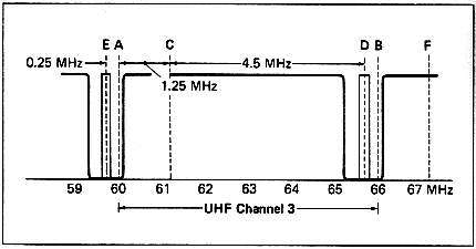
The conventional UHF tuner (channels 2 through 13) has two control knobs,
one for channel selection and the other for fine tuning. The channel selector
has a detent, a mechanical means of holding the selector precisely at the
desired position of the channel-selecting contacts. Most detents consist
of a spring-loaded roller or steel ball that slips into an indented notch
in the channel selector. The tuner's circuitry is preset for each channel's
video and audio signals.
A channel's preset video and audio signals may not be at their assigned
positions. Signal deflection from buildings, atmospheric conditions, and
even shifts caused by the station's broadcast equipment can cause a picture
to lose its sharpness and appear blurred and the sound distorted. Channel
3 signal drift can create interference with the channel 2 audio signal,
E, or the channel 4 video signal, F (see illustration).
The fine-tuning knob can correct these difficulties, but the fine-tuning
range is often insufficient to cover the 6 MHz assigned to the channel. Sections
of the broadcast frequency band therefore remain as blind spots where the
receiving unit cannot locate the broadcast signal. Because of this, the
eavesdropping unit requires a voltage-controlled oscillator (VCO) tuner that
has no preset video and audio signal circuits. If a conventional UHF tuner
is used however, its input video and audio circuitry must be bypassed and
an external VCO substituted.
A microcomputer has two prime sources of video signals. One is a chip within
the microcomputer. The HD6845P in an XT, for example, is similar to a radio
frequency modulator and emits a signal at the channel 3 or 4 frequency. To
comply with FCC regulations, this chip's signals are attenuated. If there
is insufficient attenuation of this signal, however, a portable television
set with a VCO tuner can pick up this signal up to some 10 feet away. Such
a television set in an adjoining office can be used to eavesdrop on a "noisy"
microcomputer.
The other source is the CRT of the terminal or monitor. This signal is not
confined to a preset frequency but is within the lower UHF range. The
eavesdropping unit must have a continuous signal selector. The vertical and
horizontal hold controls for the CRT's video signal are the most critical
elements of the synchronization component of the eavesdropping unit. |
Eavesdropping Countermeasures
In developing a computer security program, an organization goes through the
procedure of risk assessment. This should include consideration of the danger
from electromagnetic eavesdropping. Each organization will have to determine
how sensitive its data is and the probability that it would be stolen by
passive eavesdropping. Will it be worthwhile for a competitor to read the
firm's marketing plans or its progress in research and development? A company
specializing in mergers and takeovers is certainly a prime target. Passive
electromagnetic radiation eavesdropping is not yet a violation of law.
One way to obtain total protection against electromagnetic eavesdropping
is to place all VDTs and microcomputers in a specially prepared interior
room. This would require turning the room into a Faraday cage by lining all
the walls, ceiling, and floor with interconnected wire mesh or foil so that
there were no openings at any joints. This covering would have to be firmly
grounded. Specially designed passageways to enter or leave this area would
have to be added. In addition, RF filters would have to be on the electrical
and telephone lines, and all heating vents would have to be specially protected.
No water pipes could be in the room. Shielded telephone instruments would
have to be a minimum of 6 feet away from any computer equipment. Naturally
no ordinary business firm could operate in such an environment.
Another way would be to build a Faraday cage around each VDT and have the
employee sitting inside. Few people would wish to work in such a cell.
More reasonable countermeasures can be used against terminal and or monitor
eavesdropping, including attenuation of the transmitted signal white-noise
emitters, and random line switching.
Attenuating the signal is the Tempest approach. Standard VDTs, microcomputers,
and peripherals can be used with special protective coverings, such as the
DataProtek SHIELD (see Figure 5) in conjunction with several other measures
noted later. The SHIELD itself is a form-fitting unit, easily installed and
considerably less expensive than Tempest equipment.
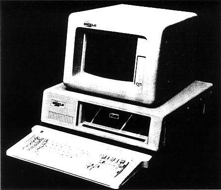
Figure 5. DataProtek's SHIELD is designed to reduce the radiation
emitted by microcomputer equipment and VDTs and reduces such RF emissions
by about 99%. When used with a microcomputer, it covers the monitor, CPU,
and keyboard with individual vacuum-formed cases of flame-retardant, metal-coated
plastic. A VDT and the keyboard are encased in the same material. The
form-fitting covers contain emission-controlling elements but do not interfere
with normal operation. A window of antiglare glass with filtering elements
reduces both radiation and glare for greater operator comfort. The SHIELD
is easy to install and matches the original equipment in appearance and color.
Additional features include filtered air ports, shielded cables for connecting
the keyboard to the microcomputer or terminal, ventilating fans, and keyboard
fascia of screen-printed metal alloy foil. |
White-noise emitters are small units placed near the VDT that set up RF
interference. Some emitters interfere with the operation of the VDT or
microcomputer. However, even if they do not, the ease with which their signals
can be separated from the VDT's emanations limits their use to protection
against only the most primitive eavesdropping devices.
Random line switching is a method of changing the way data is written to
the screen by frequent changes of the signal patterns as compared with the
standard procedure shown in Figure 3. To provide for random line switching,
the video drive circuits in the original equipment must be replaced. This
technique often produces and/or increases screen flicker. Because of the
low permutation capability of such switchers. the signals can be attacked
by a more sophisticated eavesdropper and are not very effective.
Regardless of which protection method is used, the following supplementary
countermeasures should be added.
1. All electrical power lines should be filtered to prevent RF emissions
from the equipment being transmitted along the lines that act as antennas.
This is necessary even with Tempest equipment or a product like the SHIELD.
2. If a modem is used, an internal one in a protected microcomputer
is secure. An external modem should be protected by a nickel-coated fabric
(graphite or aramid filament yarn or polyester thread).
3. Shielded cables should be used between the CPU and the monitor
as well as between the CPU and the keyboard. Similarly, a shielded cable
should be used between the VDT and its connector.
4. Monochrome monitors and VDTs should be used instead of color ones
because their level of RF emissions is generally lower.
5. All units should be securely grounded not only through the normal
electrical ground but also by using a braided wire to a building ground.
If the VDT is not protected but some protection against eavesdropping is
desired, the following precautions can be added to the list above.
1. No VDT should be placed within 50 feet from a window or outside
wall of a building. Preferably VDTs should be in an interior room without
windows. Neither situation is very practical in a normal business environment.
2. An unprotected VDT should be at least 6 feet from a telephone line.
3. VDTs should be placed at least 6 feet from any water pipes or heating
ducts. This is essential for unprotected VDTs because the pipes and ducts
act as antennas to amplify RF emissions.
Postscript
In December 1985, Computers & Security, the official journal of
the International Federation of Information Processing (IFIP) Technical Committee
on Security and Protection in Information Processing Systems, of which I
am editor, ran an article by van Eck.
The article included a technical appendix describing the basic principles
used to construct his inexpensive detection unit. After the publication of
van Eck's article, I received telephone calls and letters from individuals
who wanted to build their own versions of the van Eck unit. These people
were security specialists with military units who were responsible for Tempest
security at their posts, technicians with federal law-enforcement agencies,
computer security specialists, and technical staffs from companies interested
in producing countermeasure products.
We did not send circuit diagrams and component lists for the synchronization
recovery unit or the procedure to interface that unit with a television receiver
because of a prior agreement with Wim van Eck. We sent a copy of the van
Eck article, and I did provide answers to technical questions from those
who had television engineering and communications backgrounds.
As of early fall 1987, several individuals have produced equipment similar
to that developed by van Eck. The units have been built for special-purpose
use and not for sale to the public. A variety of antennas were used, but
the best results were obtained with a dipole antenna designed for 30-1000
MHz reception with a bandwidth of at least 4 MHz. Good results were also
obtained with a 30-300 MHz biconical antenna.
Several who were successful in building an eavesdropping unit noted that
they were helped in their design and construction by articles about pay-TV
decoders that appeared in the electronics press several years ago. It is
probably only a matter of time before the detailed circuitry for a van Eck
type of device is printed in an electronics or hobby magazine.
Reference
Note: Läckande Datorer is available only in Swedish and can be
obtained from:
Brottförebyggande radet
Informationssekretariat
Atlasmuren I
113 21 Stockholm, Sweden
Transcription and HTML by Cryptome.