SPECTRUM ANALYZERS: ALL-IN-ONE INTERFACE |
If you need assistance building a data-slicer circuit, this is the closest thing we have to a FAQ. It was written by Bonzo, and edited and revised by SirValence. Read the entire document through, and if you are still uneasy about building the circuit, then we suggest you bribe a friend to help you. Updated Mar 16/98.
If you don't know a diode from a resistor, read the BEGINNERS section at the bottom of this document.
The first thing you need to do is download the All-In-One .ZIP files and unzip them into a directory. Filenames are written in CAPITALS, but may appear on your hard drive as upper and lower case depending on your operating system.
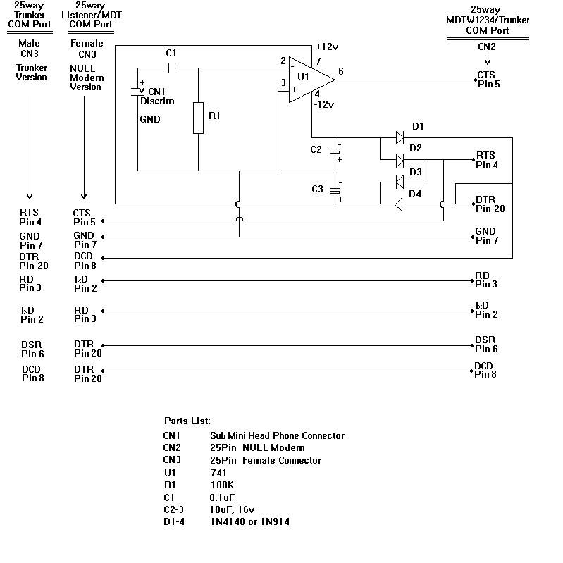
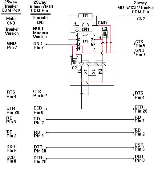
The file "allinone.jpg" shows a circuit that combines the functions of the "mdtw1234.gif" Revision B interface AND the pass-through optional connections AND the Null Modem that you will need for feeding the data to a second PC. The entire circuit will fit inside a null-modem adapter case.
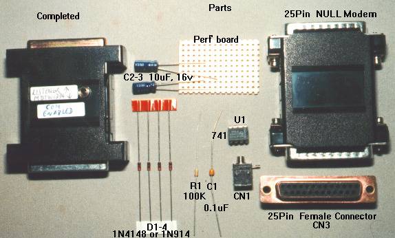
The files "step1.jpg" through "step4.jpg" have been supplied to show you how the interface is constructed.
Step 1 shows the completed unit and the various parts used to construct it. Use your browser's "BACK" button to return to this page.
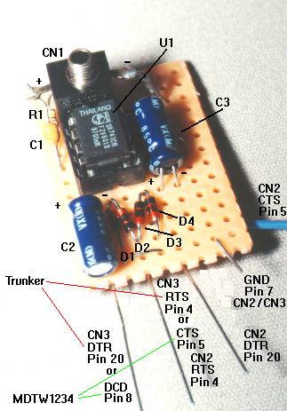
Step 2 shows the perfboard (8 by 12 matrix of holes) with the part locations.
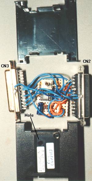
Step 3 shows the completed circuit ready for assembly in the case. Note the hole drilled into the case to expose the opening of CN1.
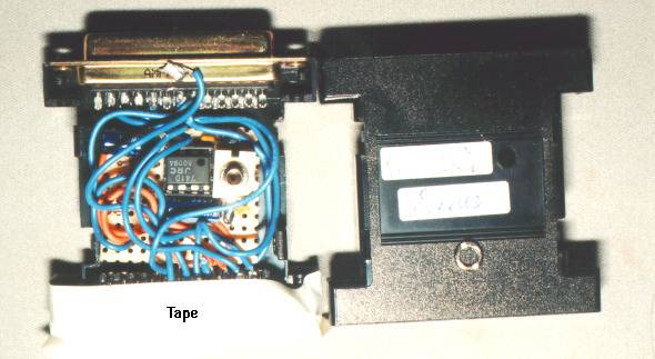
Step 4 shows masking tape used to temporarily hold CN2 (and CN3) in place while the perfboard and wires are positioned. Once the perfboard and wires are in place, you can remove the masking tape and snap the cover on. Use a thin screwdriver to move CN1 until it aligns with it's mating hole during this procedure.
By constructing the "allinone.jpg" circuit, all that is required is a standard 25-pin serial cable for connecting to the second PC.
The file "layout.jpg" shows how to lay out the parts onto a piece of non-conducting perfboard. All parts are placed on the top of the perfboard. The only exception is R1 which is wrapped around the side of CN1. This allows CN1 to to be flush with the top edge of the perfboard.
Note that traces shown in black run on the top of the perfboard. Traces shown in red run along the bottom of the perfboard. Traces can be made of component leads soldered together. Use a short piece of insulated wire where traces cross over each other. You can also strip off a section of insulation and slide it over component leads.
Your perfboard should be cut such that you have a matrix of 8 holes by 12 holes.
In the parts list of "allinone.jpg" is a 25-pin Null Modem. These typically have one 25-pin Female and one 25-pin Male connector. During circuit construction, you need to open the Null Modem case (You did buy one that you can open, right?). You will need to desolder the 25-pin Male connector and replace it with the 25-pin Female connector that you purchased separately.
The null modem case is usually held together by 4 plastic clips. If you pry each clip open in turn, and insert a short piece of wire to hold it that way, when you get to the fourth clip, the null modem case will fall apart. Be careful so that you don't break these clips.
Be sure to mark the exterior of the ALLINONE interface case such that you can tell which connector attaches to the MDTW1234 PC and which end attaches to the Listener/MDT PC, since both Female connectors will be identical. A "Brother" label-maker does a good job of this.
Handy Tip: When you are trying to pack the circuit and wires back into the case, use masking tape to hold the connectors in place. Then pack the circuit and wires in place. When you remove the masking tape, the stiffness of the wires will hold the contents in place until you can snap on the cover. See "step4.jpg".
FINDING THE PARTS:
Take your parts list and go to a REAL electronics supply store. You should be able to find an OPENABLE Null Modem at your local computer shop. RadioShack stores in Canada only carry the Non-Openable variety, so don't waste your time there.
If all else fails, you can find the following parts at your local RadioShack. Be assured that you will pay between 2 and 5 times as much for the part at RadioShack.
With the exception of the 2.5mm Head Phone socket, all the RS part numbers and prices (in Canadian dollars) are current. RS Part 274-275 was an ancient connector that was in my parts box. Apparently RS in Canada no longer carries 2.5mm Head Phone sockets. But you can ask. They DO have answers. They just don't have some parts any more.
Sub-Mini 2.5mm Head Phone socket     (RS Part 274-275)
25pin Female Connector               (RS Part 276-1548; $6.99 ea)
741 Op Amp                           (RS Part 276-0007; $2.79ea)
100K Resistor                        (RS Part 271-1347; $0.89 for 5)
Capacitor 0.1uf                      (RS Part 272-109; $3.19 for 5)
Capacitors 10uf 16V                  (RS Part 272-1025 (35vdc); $1.29ea is acceptable)
Diodes 1N4148 or 1N914               (RS Part 276-1122; $2.79 for 10)
8pin DIP IC socket (optional)        (RS Part 276-1995; $1.29 for 2)
Non-Conducting Perfboard             (with holes spaced so the legs of the 741 will fit)
If you haven't already tapped your discriminator, you'll need a few extra parts, depending upon which radio you have. Be sure to research that operation before you head off to the parts store; no sense making two trips. When you perform the work, try to avoid soldering directly to the discriminator IC's pins; instead, try to find a test-point or near-by solder pad to connect to.
BEGINNERS
If you are a newcomer to the world of electronics, you may have trouble identifying the parts and figuring out which end goes up, so to speak. Here is a primer.
The 741 Op Amp (U1) usually comes as an 8-legged DIP (Dual Inline Package); ie. it has 4 legs on each side. Stand the 741 on its legs like a little bug. That's right, a LIVE bug with its legs on the table. Now look on the top at one end for a little dimple. Orient the 741 so the dimple is farthest from you. Just to the left of the dimple is leg (or pin) number 1 (sometimes, but not always, marked with a white dot). Pin number 1 is always on a corner. Continuing counter-clockwise, the legs are numbered 2, 3 and 4. The leg closest to you on the right is 5. Progressively further away are 6, 7 and 8.
Don't forget that when you are soldering the underside of this bug, the pins will be numbered clockwise from the dimple, because you are looking from underneath.
If you bought the optional DIP socket (to avoid heat damage, and to facilitate easy replacement when troubleshooting; HIGHLY recommended if you need to read this section), it too will have a dimple at one end. It is customary to install your 741 with the dimple lined up with the corresponding dimple on the socket. That is, if you want your interface to work.
The 100K resistor (R1) is a small cylinder with wires protruding from each end. It has several coloured stripes running around it like the belt on your trousers. The resistor is not polarized; you can install it either way around in the circuit. The colours are Brown Black Yellow Gold (or Brown Black Yellow Silver).
Similarly, the 0.1uf (microfarad) capacitor (C1) is also non-polarized. It will most likely look like a little orange or yellow bead with two wires protruding from it. Install it any whichway around. Just be sure to install it in the right place.
The 10uf capacitors (C2 and C3) ARE polarized. Try to get the kind where both leads protrude from the same end. They will be marked with one lead as either (-) for negative or (+) for positive. Be sure you install them as indicated in the circuit diagram. You can use either electrolytic or tantalum capacitors.
The 1N4148 (or 1N914; they are the same for our purposes) diodes (D1, D2, D3, and D4) will be little glass cylinders with two leads and a solid line embossed on the glass at one end. On the circuit diagram, they are represented as a triangle pointing into a bar. They ARE polarized. Be sure to install them such that the embossed solid line is oriented in the same direction as the bar in the circuit diagram.
The 25pin connectors (CN2 and CN3) should have the pin numbers embossed into the plastic at the solder connection points. Try to be sparing with the solder since it is easy to form a "bridge" where solder runs between one or more leads. That would be bad.
The sub mini headphone connector (CN1) is problematic. There may be a diagram on the packaging that shows you which lead represents the "tip" (+) and which represents the "sleeve" (-) connector. Otherwise you will need to use an Ohm-meter or continuity tester to determine which lead corresponds to the tip of your patch cable and which lead represents the sleeve WHEN THE PATCH CORD IS INSERTED.
I start construction by using a dab of hot-melt glue to affix the headphone connector CN1 to the perfboard. Place it in the top-left corner of the perfboard, but be sure to leave one row of holes exposed just left of it to allow room for C1. Depending upon the design of CN1, you can either face the connector opening straight up, or out the side. I'm an upright guy. SirValence goes sideways. With just CN1 affixed to the perfboard, take some measurements and drill a hole in the null modem adapter case which lines up with the CN1 opening. If your hole does not line up perfectly, never fear as you will be able to move the perfboard about 1/4" in any direction in order to line up with your hole during final assembly.
If you have an aluminum (or aluminized) gender-changer case, you should put black electrical tape on the inside surface of the case to prevent a short-circuit.
Take your time during construction, and remember that excess heat KILLS parts! Use only as much solder and heat as necessary to make a nice, shiny connection. Do NOT blow on the solder to cool it, as that may result in a hairline crack in the solder joint from cooling too quickly. And use only resin-core solder, not acid-core (plumber's) solder.
Additional trouble-shooting help may be found in the MDTW1234 FAQ.
Good luck!