N2CBU's Technical Information Resource
Radio Shack DSP-40 Modification
- Radio Shack DSP-40 Owner's Manual Radio Shack Cat. #21-543. Includes schematics. (4.7M PDF)
- Radio Shack DSP-40 Service Manual Radio Shack Cat. #21-543. Includes schematics. (700k PDF)
- Radio Shack 21-543 DSP Amplified Speaker Mods for use with a Heath HW-8.
- eHam Reviews for Radio Shack DSP-40
- Realistic DSP-40 Digital Signal Processor for CB and Ham Radio (YouTube)
- Digital Signal Processor (DSP) Explained in Detail - Realistic DSP-40 (YouTube)
- Realistic DSP-40 Digital Signal Processor Testing (YouTube)
- Toshiba TA7227 5.5W Audio Power Amplifier (610k PDF)
- Texas Instruments TCM129C16 Combined Single-Chip PCM Codec and Filter (400k PDF)
- Texas Instruments TMS320C17 Digital Signal Processors (1.2M PDF)
Unfortunately this simple audio DSP filter has several shortcomings, but the good news is that some can be corrected and some can be mitigated. I bought two of these filters to experiment with, one to modify and one to use as a reference, when Radio Shack closed them out. I tried a wide range of tweaks and got a wide range of results although none were outstanding. Still, the simplest ones do make a worthwhile improvement and so I'm documenting them here. I'm still experimenting with the DSP-40 and will keep this page updated as my experiments progress. Feedback, suggestions and constructive criticism are most welcome!! Please note that these instructions assume you have experience with electronics and have the proper tools and equipment to do the job. If you don't, find someone who does.
Improving noise filtering on the DC power input:
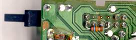
Add 0.1uF 50V ceramic bypass capacitors from the terminals of choke T1 to ground. I soldered two axial lead types between T1's terminals and the ground foil nearby (see the photos below.)
Add a 100uF 25V radial lead electrolytic capacitor from the output side of choke T1 to ground. Drill two holes to accommodate the capacitor's leads (see the photos below) and bend and solder the leads as shown.
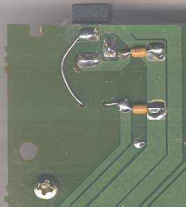
In some instances it's possible this modification will actually increase noise pickup because the capacitors connected to choke T1's output open up an AC path from ground to the filtered supply side. However, I found that the modification actually reduced AC noise and RF pickup in my DSP-40 so I'm documenting it here.
Improving noise filtering on the audio input and output:
Add 0.01uF 50V ceramic bypass capacitors across the audio input and output connectors. I soldered axial lead types across the connectors on the solder side of the PCB (see the photo below.)
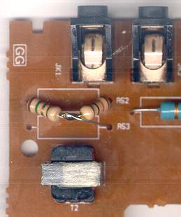
Remove R52 and R53 (both are 47 Ohm 2 Watt resistors.)
Series connect a 10 Ohm and a 2 Ohm 1/2 Watt resistor and install them in the former position of R52. Be certain to install the resistors so that the 2 Ohm resistor end is connected to the input connector "ring." This is the hole nearest the edge of the PC board (see the photos below.)
Install a short length of wire between the junction of the 10 and 2 Ohm resistors and the innermost PCB hole at the former position of R53 (the audio input connector "tip" -- see the photos below.)
Cut the PCB trace between the former R52 and R53 locations on the audio input connector "tip" side (see the photos below.)
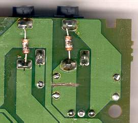
This modification provides RF bypassing, a resistive near-8-Ohm load for your radio's audio amplifier and reduces the sensitivity of the DSP-40's input. Previously, the high sensitivity of the DSP-40 required very low volume settings from the receiver. This caused a signal to noise ratio degradation if there was any AF noise generated by the receiver's audio power amplifier. Because the receiver's audio amplifier can now be run at higher output levels the received audio is considerably "louder" and the noise is effectively masked.
The exact values of the resistors aren't critical. I used what I had on hand and the configuration just evolved from experimentation. Alternatively you can cut the PCB trace, tack solder some test leads to the appropriate PCB locations and then experiment with different resistor values and configurations. Just be sure to keep the audio input and T2's primary loaded down. Keep in mind that putting a high value resistor in series with T2's primary unloads the transformer and increases noise pickup.
Increasing the maximum volume level:
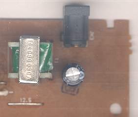
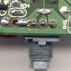
Remove R34, a 200k Ohm SMT resistor, and replace it with a similar 24k Ohm resistor (see the photo below.)
Install a 1000pF SMT capacitor across the volume control potentiometer at the blank PCB pads located midway between it's resistance and On-Off switch leads (see the photo below.) This is just to the right of R34. This adds RF bypassing and helps to attenuate some of the high frequency digital noise generated in the DSP section. There's still plenty of digital high frequency noise though.
Remove C33 and C38 (both are 2.2uF electrolytic capacitors) and replace them with 0.1uF polyester or other audio-quality capacitors. These two capacitors are located just underneath the red "power" LED. Reducing the value of these capacitors attenuates 60Hz hum and other annoying low frequency energy.
Please note that this modification seems to reduce the effectiveness of the DSP-On/Off pop-eliminator circuit (Q1-3.) The pop-eliminator didn't work very well to begin with so to remedy this and improve the pop-eliminator beyond it's original capability see the section titled "Fixing the Pop-Eliminator" below.
Balancing DSP-On vs. DSP-Off audio levels:
Cut the PCB trace between SW3a-Off and SW3b-Off (see the photo below.) The trace runs between the two rows of SW3's pins.
Install a 16k Ohm 1/8 Watt resistor between the two pins of SW3 referenced in step #1 (see the photo below.)
This modification attenuates the audio path when the DSP-40 is in bypass or DSP-Off mode. Before the modification it was necessary to adjust the volume control when switching the DSP filter in and out of the audio path. Once again, the value of the resistor isn't very critical. I just experimented until I found what sounded to me to be a comfortable balance between the two modes. Please note that there is some interaction between this modification and the "Increasing the maximum volume level" modification. It's best to perform that modification first if you plan to experiment with resistor values.
Fixing the Pop-Eliminator:
Replace C37, a 220pF SMT capacitor, with a 1000pF SMT capacitor (see the photo below -- C37 is in the upper left-hand corner.)
Replace C36, a 0.047uF SMT capacitor, with a 0.1uF SMT capacitor (see the photo below -- C36 is located just to the left of R42.)
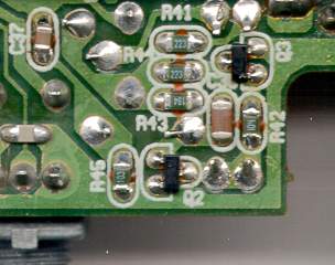
I didn't have any 0.1uF SMT size 0805 capacitors on hand so I used a SMT size 1206 capacitor. The pad size and spacing is just enough to accommodate the size 1206 capacitor. This modification increases the sensitivity and blanking time of the pop-eliminator circuit built around Q1, Q2 and Q3. This circuit is supposed to act like a noise blanker and clip out the spikes caused when the DSP-40 is powered on and when the DSP mode is engaged and disengaged.
That's all for now... 01/11/2001.