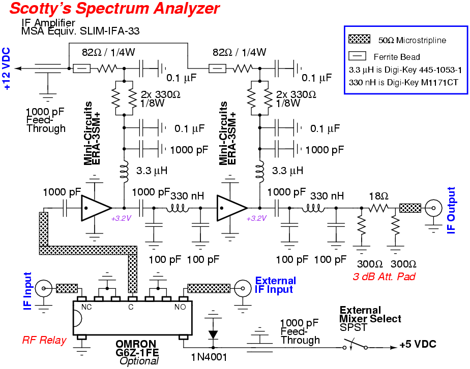
This is my version of the Intermediate Frequency (IF) amplifier for Scotty Sprowls' Modularized Spectrum Analyzer (MSA) project. The original IF amplifier design is SLIM-IFA-33.
The IF amplifier module consists of two separate Mini-Circuits ERA-3SM+ MMIC amplifiers with a common +12 VDC power input connector. The MMICs have a bandwidth of over 4 GHz, so a 40 MHz low-pass filter is included in each output. Scotty's original design used Mini-Circuits ERA-33SM MMICs, but ERA-3SM+ MMICs are easily found on eBay.
At 10.7 MHz, the single stage gain is approximately 23 dB, with a 1 dB compression point output of greater than +12 dBm and noise figure less than 3 dB. 35 mA of bias current (for each amplifier) is required to maintain these specifications. With +12 volts input to the module, a total of 251 ohms dropping resistance is required. The dropping resistance is split into two, with two parallel 330 ohm resistors in series with a 82 ohm resistor. The 308 mW of power dissipation is also split between the two sets of resistors. Using split resistors allows for more input DC power filtering.
The original module design was given the suffix "-33" because it specified using the Mini-Circuits ERA-33SM MMIC. However, other MMIC's can be substituted with appropriate bias resistor changes.
After Scotty designed the first SLIM-IFA-33 module, it was determined that component tolerances were not tight enough to guarantee consistant bandwidth characteristics. Therefore, later revisions changed the band-pass filter in each output stage to a 40 MHz 3-pole low-pass filter.
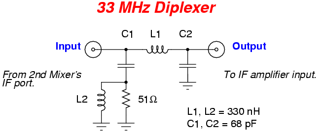
Ahead of the IF amplifier (on the 2nd mixer's IF output) is a circuit called a diplexer. Wideband frequencies (and noise) exiting the 2nd mixer at the IF port will "see" a dual-path at the junction of L1 and C1. Frequencies higher than 33 MHz follow C1 and get absorbed by the 50 ohm resistor load. Frequencies lower than 33 MHz follow L1 and are sent off to the IF amplifier stage. This circuit gives the mixer a constant 50 ohm impedance over a very wide frequency range, reducing the chances of intermodulation distortion. The diplexer can be easily redesigned for any crossover frequency point.
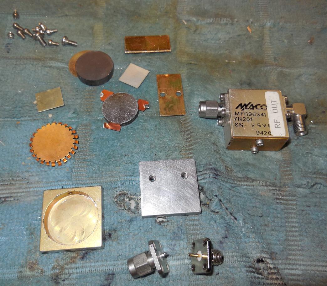
Internal view of a M/A-Com 7N201 800-900 MHz band isolator.
The isolator will be taken apart and used to hold a circuit board for the 33 MHz diplexer circuit.
This is optional, but the diplexer should be mounted as close to the mixer's IF output as possible.
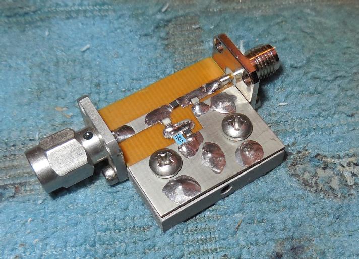
Completed 33 MHz diplexer circuit board mounted inside the isolator's body.
The input (mixer IF output) is via the male SMA connector.
This diplexer circuit will be suitable for a spectrum analyzer with a 10.7 or 21.4 MHz IF.
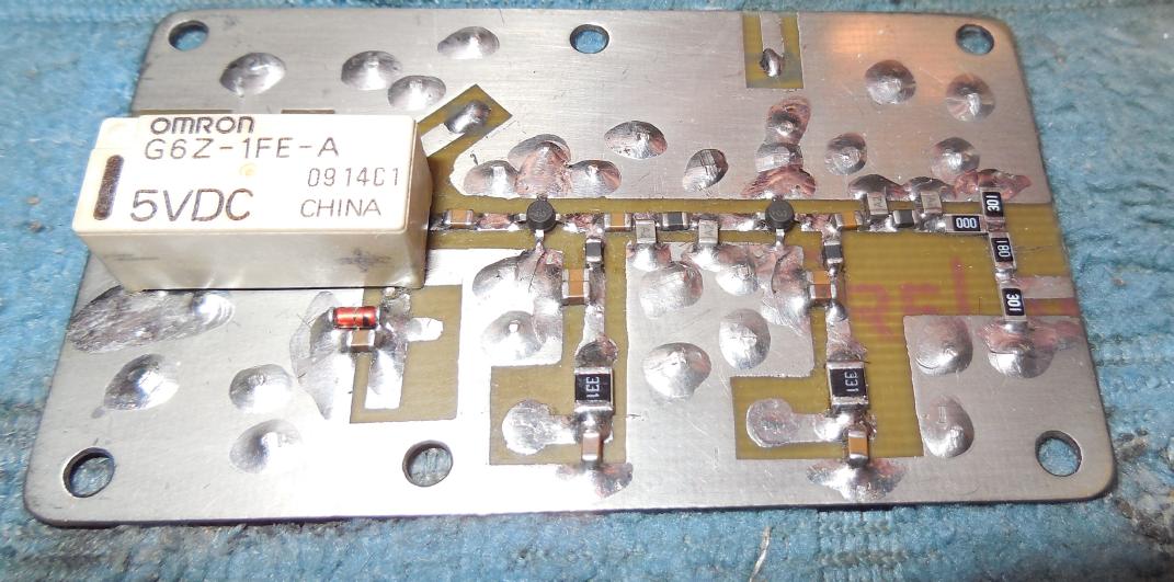
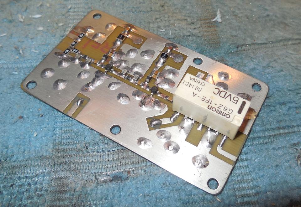
Overview of the IF amplifier circuit board.
On the input to the IF amplifier is an optional OMRON G6Z-series SPDT RF relay. This allows the input of an external IF frequency, such as from an external mixer or tuner. This can be a very handy feature for increasing the frequency response of the spectrum analyzer..
The two little black round devices are the Mini-Circuits ERA-3SM+ MMICs. The dot near one of the pins is the RF input.
A 3 dB attenuator pad on the output of the final ERA-3SM+ helps the total circuit "see" a 50 ohm load, and will help swamp out and impedance mismatches from the resolution filter stage the IF amplifier will drive.
Alternate view.
All the capacitors and inductors in the RF chain of this circuit must be surface-mount for proper operation.
The circuit board should also have a large ground plane and proper RF circuit layout (isolated inputs/outputs and clean DC power).
The two 3-pole 40 MHz low-pass filters help to limit the frequency range, and hence noise, of this IF amplifier circuit.
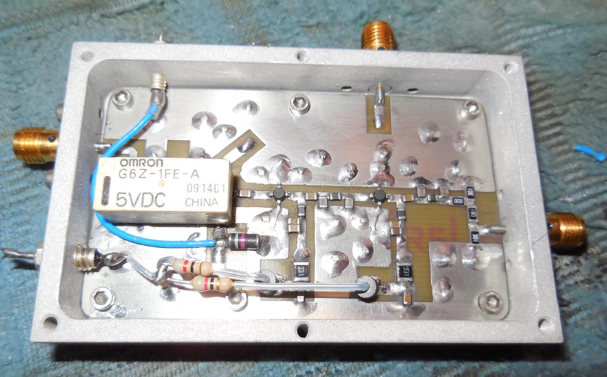
The bias resistor for the MMICs was split into two for additional supply decoupling and filtering.
They'll need to dissipate around 300 mW total power, so using 1/4 watt resistors is recommended.
Try to use 1% tolerance metal-film resistors, but it's not necessary.
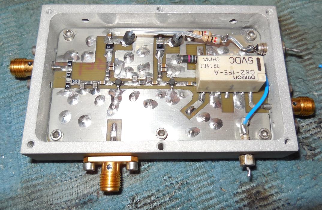
Alternate view.
The SMA jack along the bottom is for the remote IF input, which will be from a future panel-mounted connector.
That input is selected by energizing the RF relay.
1000 pF feed-through capacitors supply the amplifier's main +12 VDC input (right-side) and the +5 VDC for the relay (bottom).
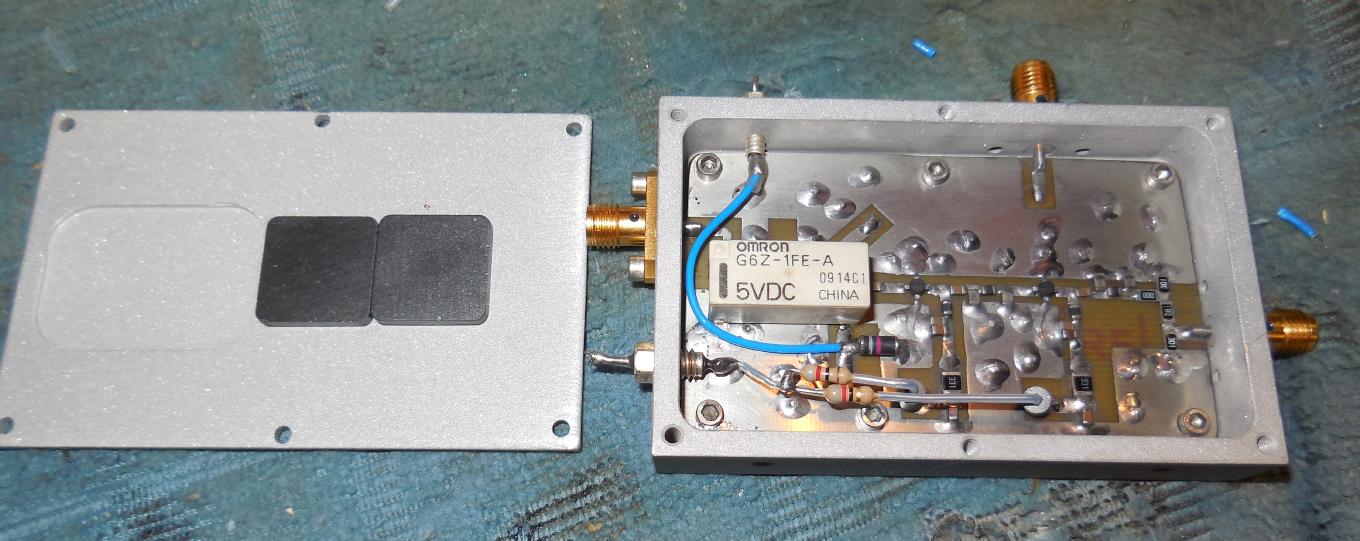
Finished case overview.
The lid of the case has a few stick-on ferrite EMI absorption plates (Digi-Key Part: 240-2264-ND). These are optional, but the idea is to help reduce the chance of the internal cavity resonating, which can turn the amplifier into an oscillator.
Check the IF amplifier for proper operation by monitoring the overall current draw. It should be a steady 70 mA or so. Any more than this, or any sign of current "spiking," could indicate that the circuit is oscillating and is not properly functioning.
Each MMIC should have a steady +3.2 VDC on its output leg when powered from +12 VDC and properly biased.
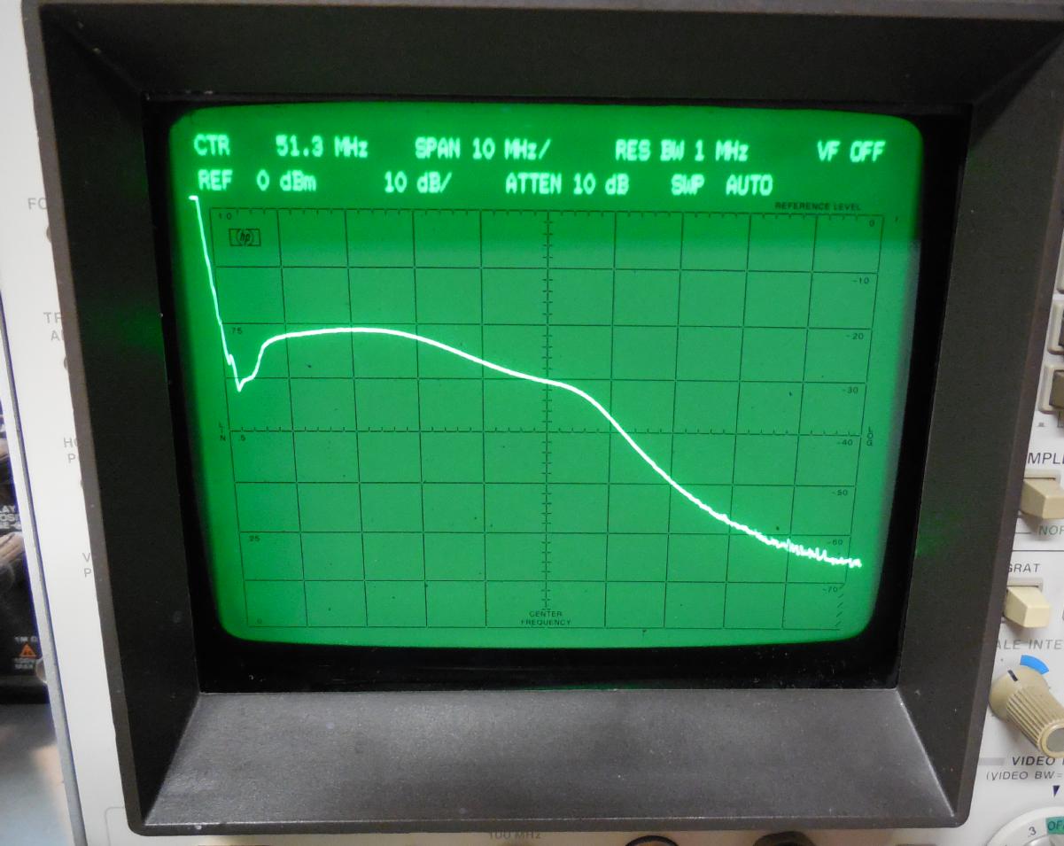
Tracking generator plot of the IF amplifier module.
The zero spur is on the left.
Center frequency is 51.3 MHz. 10 MHz per horizontal division, 10 dB per vertical division.
RF input power to the amplifier was around -60 dBm.
The low-pass filtering starts around 40 MHz.
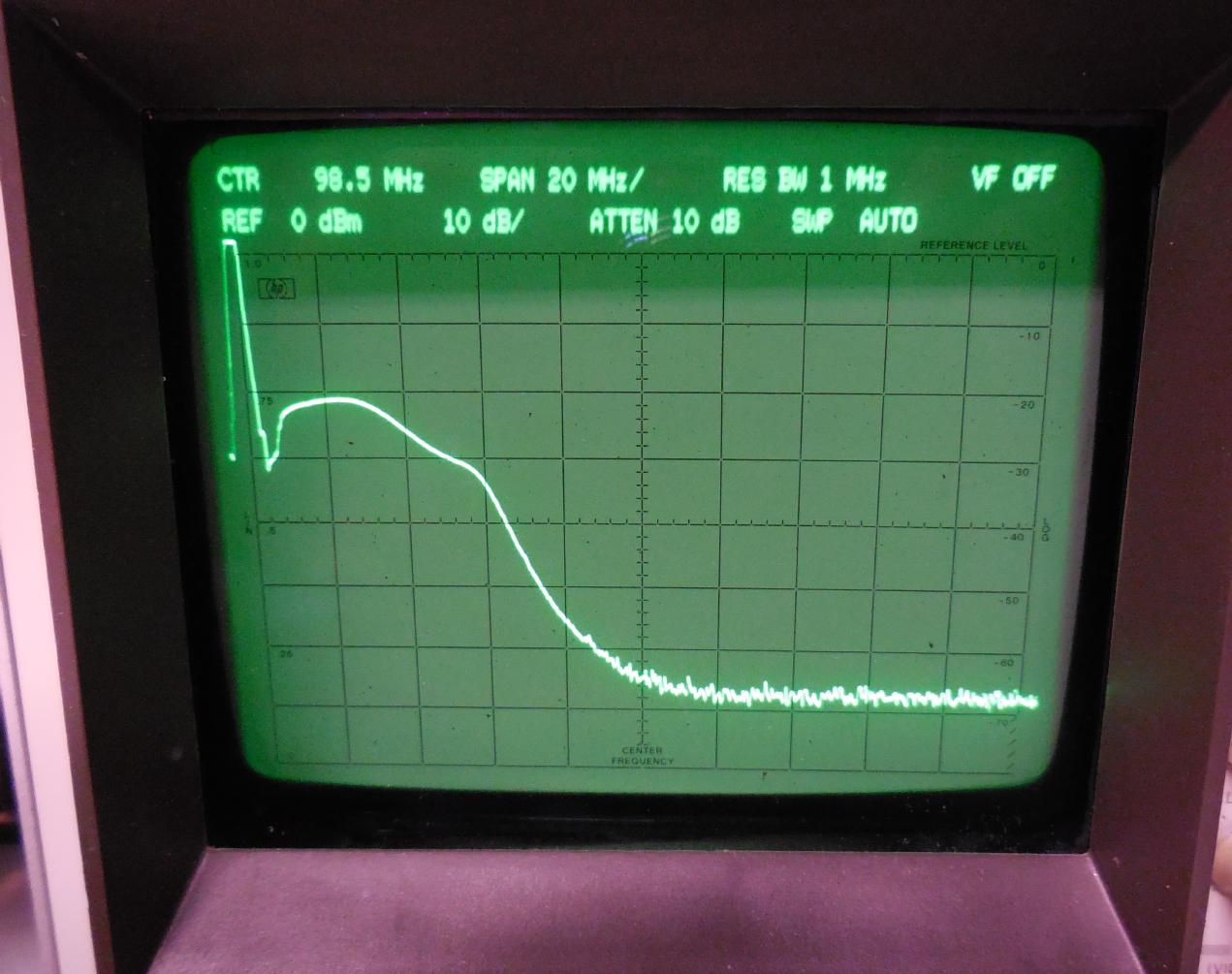
Tracking generator plot of the IF amplifier module.
The zero spur is on the left.
Center frequency is 98.5 MHz. 20 MHz per horizontal division, 10 dB per vertical division.
RF input power to the amplifier was around -60 dBm.
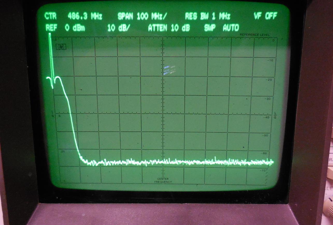
Tracking generator plot of the IF amplifier module.
The zero spur is on the left.
Center frequency is 486.3 MHz. 100 MHz per horizontal division, 10 dB per vertical division.
RF input power to the amplifier was around -60 dBm.