

Cable TV Scrambling Theory
Download The Descrambler Project
Modifications & Troubleshooting
Tips
Interference Filter Project
Sources
to Purchase the Descrambler Project
Sources
to Purchase the Filter Project
New Circuit For Cable Descrambling??
MagicBoxes New Design For Cable Descrambling
All projects presented at this web site are for
educational puposes only and not to be used to defraud the cable company or any other
individuals. I am not responsible for anyone building or using any of the projects at this
site.

NTSC Format
Before we can discuss scrambling theory we must have an understanding of the NTSC format. The standard in which the U.S. uses to transmit a television signal. I have a file NTSC.ZIP which is very informitive. Shown below is a simplified composite video diagram of the NTSC signal.
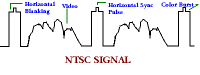
As you can see the video portion of the signal is between regular pulses. The high amplitude regular shaped pulses are made up of several componets. The horizontal blanking pulse is the widest part and is used to turn off the CRT during the vertical retrace. This prevents the vertical retrace lines from showing up on the screen. On top of the blanking pulse is the horizontal-sync pulse. Its purpose is to synchronize the sweep circuitry in the TV with the video signal. After the horizontal-sync pulse's trailing edge and before the blanking pulse's trailing edge is the color burst signal. This area is called the "backporch". The color burst signal is a 3.58Mhz sinewave that is used to synchronize the color circuitry in the TV. In a standard picture signal there are 15,750 horizontal and 30 vertical frames per second. To understand the many methods of scrambling it is important to remember that the horizontal and vertical pulses and the color burst signal are used for timing and are needed to reconstruct a TV picture. If any of those signals are absent, distorted or changed in any way the TV picture will not be synchronized. The picture will be unwatchable. The picture will tear, roll, and the colors may be incorrect and will appear like the picture at the beginning of this page.
The audio in the NTSC format is frequency modulated on a 4.5 Mhz signal that is added to the composite video signal. The audio portion of a TV works like a standard FM radio and therefore the signal is similar.
Scrambling Techniques
There are a few key components that can be altered to cause a picture to be unwatchable. These key componets are the sync pulses, color burst signal and the video signal also the audio signal can be modified to disable the audio portion. Most scrambling today is done using a form of sync suppresion.
Video Inversion
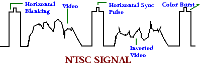
One of the most simplest forms of scrambling is to reverse the polarity of the video information. This may cause the TV not to sync up and the picture will tear and roll. If the TV does sync up then the picture will appear as a negative picture. The dark areas will be light and light areas will be dark. The colors will be reversed and cause faces to be blue and the sky to be brown. Inverted video is very easy to fix; all that needs to be done is to re-invert the video again. A slightly more sophisticated version of this method is to invert the video at different intervals during the frame. The picture would flicker or have a superimposed pattern. Typically this method is not used by itself because it is very easy to disable, it is usually used with another form of scrambling.
Sine-Wave Scrambling
One way to alter the sync pulses is to add a sinewave to the video signal. With this method a 15.75khz sinewave is added. If the sinewave and the video signal is summed properly it is posible for the sync pulse to reduce and the video signal to be higher. As shown in the picture below, the sync pulse ids now below the video signal. This will cause the sync circuits in the TV not to function properly.
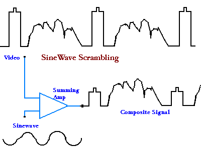
To unscramble the signal all you need to do is mix a sinewave of the same type to the video signal and it will cancel out and restore the video to normal. The sinewave is typicaly added to the audio signal.
Gated-Sync Scrambling
This method is very similar to the sinewave scrambling except that a square wave is used to reduce the signal level of the sync pulses. As you can see from the diagram a negative pulse is added to the video signal so that the negative pulses will reduce the level of the sync pulses below the video signal information. The result is a scrambled picture because the TV sync circuits cannot lock onto the sync signal.
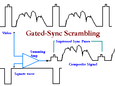
To descramble a gated-sync method, a proper square wave needs to be mixed to the scrambled signal and the sync pulses will be restored to the orignal size. The most common way for the cable company to provide the square wave is to add it to the audio signal and then all you need to do is strip it away. In the out band gated sync method the correcting wave can be attached to any frequency that the cable can handle. With this method the frequency would have to be known and and then the correcting wave could be extracted. Typical frequecys are 50MHz and any frequency between 90MHz and 114MHz.
SSAVI Scrambling
One of the most commonly used scrambling methods is the SSAVI system. SSAVI stands for Scrambled Sync And Video Inversion. This system has four modes of operation.
With this scrambling method the horizontal scan lines are very important. Scan lines 0 to 9 are normal. Scan lines 10, 11 and 12 contain the subscribers code number. Line 13 is the market code. If all codes match to what is stored in the on board PROM then the unit will descramble the picture signal. Scan lines 27 to 260 are scrambled. Scan lines 261. 262 and 0 to 26 are normal. scan line 20 is the key to the unit. It will determine whether the frame has inverted video. Typically if the video is normal then the first part of line 20 will be white and the last part will be black. If the video is to be inverted then line 20 will be all white.
Universal Descrambler Project
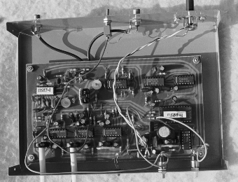

The universal descrambler originated from an article in Radio Electronics magazine in May 1990. Its was written for educational purposes only so that technical people could understand cable TV scrambling techniques and how to restore video sync signals.
Typically cable operaters scramble premium channels by surppressing the sync pulses, which are used to to stablize the the picture on the TV screen. If the pulses are surppressed in any way the TV picture will tear and roll. The methods used to scramble the picture is to alter the amplitude of the sync pulse or cause it to be omited entirely from the video signal. Occasionally the sync pulse amplitude may be caused to vary at different times.
In order to view the scrambled picture, the sync pulse must be reconstructed to its original amplitude. Some descrambleing techniques utilize a key of some type to reference and thereby restore the pulse to its original level. This key or pilot signal can be an audio subcarrier of some frequency that is a ratio of the horizontal sync frequency of 15.734 KHz.
Some systems have a digital signal that activates the decoder. Other methods are the pilotless where horizontal pulses are attached to the vertical sync which will lock the horizontal frequency oscillator and reproduce the sync pulses. All these methods thus far regenerate the horizonal sync pulse by means of other timeing signals. The universal descrambler doesn't use any of the methods discussed to regenerate the sync pulses.
The universal descrambler utilizes the color burst signal, which is present in all NTSC video signals ( 3.58 MHz ). This signal is the key for regenerating all other timing signals to produce a clear picture. The circuit uses a CD2240 CMOS LSI ( video sync generator ) to produce the vertical and horizontal sync pulses.
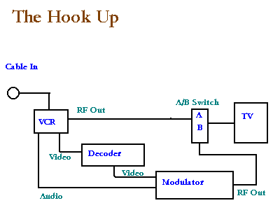
If you decide to build one of these units and need help please email me. I have collected many fixes for common problems and have mods to improve the unit. Before building this unit, you must make certain that you have a baseband video source that is able to tune in the scrambled station. One such source is the video output on the back of your VCR. Most of the newer VCR's will not lock onto a scrambled station. It will produce a blue screen on your TV, therefore you need to obtain and older VCR that will allow you to view a scrambled station or find another source for the baseband video.
Remember, this information is for educational purposes and it is your responsibility to inform your cable company before hooking this unit up to their system.
UPDATE 7/27/97 A SOURCE HAS
BEEN FOUND.
A company in Indiana sells this unit preassembled. They can be
contacted at R.C. Distributing P.O Box 552 South Bend ,IN 46624. Phone : 219-236-5776.
UPDATE 12/31/97 ANOTHER SOURCE
HAS BEEN FOUND.
Thanks to an email I received in response to my web site, I was
informed that North Coutry Radio sells the kit. They have it listed at thier site as a
Sync Regenarator. The web site is http://www.northcountryradio.com
UPDATE 01/10/99 ANOTHER SOURCE
HAS BEEN FOUND.
Thanks to an email I received in response to my web site, I was
informed that Surplus Traders is liquidating whole units and kits. You can find it listed near the end of thier site.
The web site is http://www.73.com/a/0249.shtml
UPDATE 01/30/99 ANOTHER SOURCE
HAS BEEN FOUND.
Thanks to an email I received in response to my web site, I was
informed that A1 Electronic Parts is selling the kits.The web site is http://www.a1parts.com
Modifications & Troubleshooting
The following are modifications you can try to improve the picture quality and
operation of the descrambler. You should try each individual mod and look for improvement.
If there is no improvement then remove the mod.
The first mod is the most important one. Place a momentary switch on pin 10 of IC6 to gnd. By pushing the switch the circuit will lock quickly. Then adjust the horizontal and vertical to make the picture viewable.
To remove ripple in the picture adjust C32 and to fine tune the tint
adjust C24. Change C32 and C24 trimmer caps to Radio Shack Part# 272-1340. They are
more stable then some of the trimmer caps supplied in the kits. Change R2 to 5k
ohms Radio Shack Part# 271-1314. Mount U2 and U11 off the board and heat sink them
to the case. Don't do this to the -5v regulator. Ground the crystal case to C22 (gnd) with
a low wattage iron. Change C30 to 100pf and change C21 to 1uf. You should have a 1.2volt
input signal. To obtain this lift one leg of R1. If this helps try a different value for
R1 any where from 75 to 600ohms. Changing R29 to 1.1k ohms may help the operation
of the unit but it may also limit C32 from adjusting the tint properly. The 3.58mhz
reference oscillator circuit is the most important part of the project. If you cannot get
your unit to lock horizontally try a different vaule for C23; 7pf to 12pf have been tried.
Also try C25 as 18pf or remove it altogether. To fix tint problems try either a
higher value for C32 by placing a 32pf cap in parallel or reduce the capacitance by
changing C30 from 56pf to 33pf. For incorrect color on negative video, disconnect
C17 from J1 and reconnect it to pin 15 of IC2b
Voltages and Frequencies
| Pin # | Voltage |
| 1 | -.15 |
| 2 | 0 |
| 3 | -.95 |
| 4 | -.88 |
| 5 | -4.83 |
| 6 | 0 |
| 7 | 2.21 |
| 8 | 2.14 |
| 9 | 0 |
| 10 | 4.7 |
| 11 | -.88 |
| 12 | 0 |
| 13 | .41 |
| 14 | -.15 |
| Pin # | Voltage / Freq. |
| 1 | 2.2 |
| 2 | 2.2 |
| 3 | .31 adj. R9 |
| 4 | .31 adj. R9 |
| 5 | 0 |
| 6 | 0 |
| 7 | -4.9 |
| 8 | 0 |
| 9 | 3.62 / 14.4khz |
| 10 | 5 adj. S3 |
| 11 | 3.8 / 15.75khz |
| 12 | .01 |
| 13 | .41 |
| 14 | .43 |
| 15 | 2.19 |
| 16 | 4.78 |
| Pin # | Voltage / Freq. |
| 1 | .31 adj. R9 |
| 2 | -.3 adj. R14 |
| 3 | 0 |
| 4 | 0 |
| 5 | 0 |
| 6 | 0 |
| 7 | -4.9 |
| 8 | 0 |
| 9 | 0 |
| 10 | 3.5 ->4 /16.29khz |
| 11 | 3.8 / 15.75khz |
| 12 | 0 / 3.58mhz |
| 13 | .28 |
| 14 | .28 |
| 15 | .27 adj. R9 |
| 16 | 4.9 |
| Pin # | Voltage |
| 1 | 2.68 |
| 2 | 2.68 |
| 3 | 1.95 |
| 4 | 2.46 |
| 5 | 2.37 |
| 6 | 2.82 |
| 7 | 0 |
| 8 | 4.81 |
| 9 | 0 |
| 10 | 0 |
| 11 | 4.81 |
| 12 | 0 |
| 13 | 0 |
| 14 | 5 |
| Pin # | Voltage / Freq. |
| 1 | 2.25 |
| 2 | 8.46 |
| 3 | 8.46 |
| 4 | 8.66 |
| 5 | 0 |
| 6 | 8.59 / 3.58mhz |
| 7 | 2.16 / 3.58mhz |
| 8 | 8.98 / 3.58mhz |
| 9 | .15 / 15.75khz |
| 10 | 8.73 |
| 11 | 8.9 |
| 12 | 11.9 |
| 13 | 0 |
| 14 | .43 |
| 15 | 11.43 |
| 16 | 0 |
| Pin # | Voltage / Freq. |
| 1 | 0 |
| 2 | 5.57 |
| 3 | 5.61 |
| 4 | 5.13 |
| 5 | 5.66 |
| 6 | 5.09 / 3.58mhz |
| 7 | 5.93 |
| 8 | 0 |
| 9 | 6.93 |
| 10 | 4 |
| 11 | .44 |
| 12 | 5 |
| 13 | 5.12 |
| 14 | 0 |
| 15 | .02 |
| 16 | 11.21 |
| Pin # | Voltage |
| 1 | 4.41 |
| 2 | 1.36 |
| 3 | 2.22 |
| 4 | 3.9 |
| 5 | 3.66 |
| 6 | .88 |
| 7 | .88 |
| 8 | 0 |
| 9 | 1.83 |
| 10 | 4.41 |
| 11 | 3.4 |
| 12 | 2.18 |
| 13 | 2.18 |
| 14 | 2.19 |
| 15 | 1.34 |
| 16 | .26 |
| Pin # | Voltage |
| 1 | 2.25 |
| 2 | 2.21 |
| 3 | 2.22 |
| 4 | 2.21 |
| 5 | 2.22 |
| 6 | 2.22 |
| 7 | 2.23 |
| 8 | 0 |
| 9 | 2.32 |
| 10 | 1.83 |
| 11 | 0 |
| 12 | 2.21 |
| 13 | 2.21 |
| 14 | 2.21 |
| 15 | 2.22 |
| 16 | 4.41 |
| Pin # | Voltage / Freq. |
| 1 | 0 |
| 2 | 2.08 |
| 3 | 0 |
| 4 | 4.52 |
| 5 | 4.46 / 16.29khz |
| 6 | 2.27 |
| 7 | 4.17 |
| 8 | 4.81 |
| 9 | 4.64 |
| 10 | 4.82 |
| 11 | 3.89 / 15.75khz |
| 12 | 0 |
| 13 | 3.62 / 14.55khz |
| 14 | 3.19 |
| 15 | 0 |
| 16 | 4.76 |
| 17 | 4.43 |
| 18 | 0 |
| 19 | 4.82 |
| 20 | 4.75 |
| 21 | 0 |
| 22 | 0 |
| 23 | 1.82 / 502khz |
| 24 | 4.82 |
| No. | Emitter | Base | Collector |
| Q1 | -.01 | -.01 | -.01 |
| Q2 | 0 | .78 | .15 |
| Q3 | 0 | .51 | 5.52 |
| Q4 | .44 | 1.02 | 11.2 |
| Q5 | -.4 | .27 | 4.63 |
| Q6 | .28 | -.4 | -4.96 |
Download the File
Push the Button Now
NEW DESIGN ON THE INTERNET FOR DESCRAMBLING CABLE?
Thanks to an email I received, I was informed that there may be a new circuit out there on the web in the form of a kit or fully assembled. Its a whole new design that uses a pic controller to provide all the timing signals. They have a parts listing at their site and a schematic. They provide you with a description of how it hooks up to a cable box and pricing info. I am searching for info on this product. Please contact me if you have dealt with the company; have either purchased the product or built it. How did it work? All feedback will be posted. Here is some info I received from email.
Randy I spend a little time looking at the diagram. Something is quite cool, something is difficult to understand, or as I believe is done in a "funny" way. Ok the input stage, superclassic 733 unitary gain with the 2 output that will be used later on for straight or reverse signal. There isn't chroma regeneration with a PLL, there is a second 733 fetching some of the video signal and with a 2 taps filter (1 serial + 1 parallel) amplify the 3.58 MHz. At least I believe so, without the values for the resonant circuit I can't really tell but since there are trimming capacitors I believe that I'm accurate here. Now the part that I don' understand. As I said in my previous email I don't see how is possible to sync-up a PIC with a 3.58 MHz signal. I was hoping that they may enter the pre-scaler input of the built-in counter but actually they don't. They just go into generic I/Os and I've to use the plural here since they are using two of them !!!! I don't see the reason. One possibility is that they use in a very ugly way the color burst to start an interrupt and then a following chain of events will generate at a fix delay the following sync. This is a possibility but in this case they don't allow the repositioning of the chroma if has been shifted. However in Europe I never saw cases of shifted chroma, they need to have very cheap descrambler when the cables companies buy millions of them and they try to minimize unnecessary costs. I like the 4052 used for re-synthesize the correct TV waveform, it's pretty elegant. What I don't like about the output stage is that we have a signal here travelling quite a bit and there is basically no amplification. I'm assuming the will be about 20% weaker at the output. I believe that our PIC behave also as counter and sample the video signal with the 2 comparators in order to understand if the field is positive or negative and in case issue the right binary code to the 4052 in order to delivery the right polarity. I wish to know your point of view about this analysis. Now I've a question, I wish to build the analog decoder that you did. However seem to me that 99$ is a steal . Do you know if is possible to find just the PCB? I saw to potentiometers on the circuit. Do you need to tune them often? This look quite ugly.
You get your own look at the circuit or contact the company at
http://www.connectrix.com.
MAGICBOXES DESIGN FOR DESCRAMBLING CABLE
The 393 fires on fast transitions - ie (sync rise and fall) When the sync is rasied(supression) , the "transistion" occurs earlier than normal sync. These signals are fed to the pic. The pic is clocked at 20Mhz but slows its own clock speed 50Khz by firing the zener (varactor) on the crystal. This allows me to syncronize the pic clock with the horizontal blanking interval. You will notice the pic is slowed down every 2-3 horizontal syncs... This method allows for accurate syncronization to about .25uS on the sync. The pic then creates a new sync, re-inserts the colour burst, and will trigger a video invert if needed. This keeps the cost down and the building easy. The circuit is really plug and play - just turn the course varicap adjustment until the picture is locked. (it will wave when not). MUCH better quality than the universal (which I consider shit). ***This circuit never requires any tuning once initially set.
 Interference Filter for Cable TV
There is a misconception on the internet that there is a universal descrambler circuit that can be built with a handful of parts at Radio Shack for $12.00. The circuit in question has absolutely nothing to to with descrambling; it is simply a notch filter to remove an interference signal that cable companies put on a premium channel, thereby preventing the viewer from watching the channel. Typicaly if a cable company uses this method, of rendering the channel unvieable, the picture will have black bars on it and the audio has a bleeping noise. What the cable company has done is to add an interference signal in between the audio and video carrier signals for that channel and thereby causing the affect mentioned. This is different from the normal descrambling tecniques of suppressing the sync pulses which will cause the picture to tear and roll. To make the picture viewable with an interference signal you use a notch fiter. The circuit described is such a filter and the parts can be obtained at a local Radio Shack store. I have added a source listing to purchase the filter also.
MATERIALS REQUIRED
INSTRUCTIONS
1. Bare a length of No. 12 gauge solid copper wire and twist around a 3/8" nail or
rod to form a coil of 9 turns. Elongate coil to a length of 1 1/2" inches and form
right angle bends on each end.
2. Solder the varible capacitor to the coil. It doesn't matter where you solder it, it
still does the same job. The best place for it is in the center with the adjustment screw
facing upward. Note: When it comes time to place coil in box, the coil must be insulated
from grounding. This can be done by crazy- glueing a piece of rubber to the bottom of the
box, and securing the coil to it.
3. Tap coil at points 2 1/2 turns from ends of coil and solder to coaxial chassis
connectors, bringing tap leads through holes in chassis box. Use as little wire as
possible.
4. Solder resistor to center of coil and ground other end of resistor to chassis box,
using solder lug and small screw. Diagram: Your circut and design should look like this:
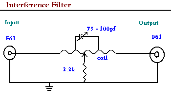
5. Drill a 1/2" diameter hold in mini-box cover to permit adjustment of the
variable capacitor from the outside. Inspect the device for defects in workmanship and
place cover on mini-box. Tighten securely.
6. Place device in line with existing cable on either side of the coverter box and
connect to television set with the short piece of RG59 coaxial cable. Set television set
to unwatchable channel.
7. Using a plastic screwdriver (non-metallic), adjust the varible capacitor until
picture tunes in.
Download the File
Push the Button Now
Rainbow Kits 6227 Coffman Rd. Indianapolis,IN 46268 Tel: 317-291-7262 www.rainbowkits.com
Video Media P.O. Box 93/6025 Margate,Fl. 33093-6025 Tel: 954-752-9202 www.tvfilter.com