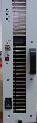
Spectrian Model SCPA1063W
| Putting the Spectrian Amplifier on 2304 MHz |
| Original Work by Randy Bynum, NR6CA |
- www.nr6ca.org/spectrian.html Original information website.
- 30 Watt Class A Linear RF amplifier for 2.3 GHz by Joseph Ruggieri, KI4NPV
- 75 Watt Linear RF Amplifier Board for 2.3 GHz by Joseph Ruggieri, KI4NPV
- Spectrian RF Amplifier Board Notes For the amplifier board with the three XRF286s, by Joseph Ruggieri, KI4NPV
- Spectrian 180W Amplifier Use on 13 cm EME Information on usings the high-power RF amplifier boards.
- XRF286 Amplifiers for 23 cm by W6PQL
- Converting the Spectrian SCPA1063W Amplifier on 13 cm by ON4IY
- Remote Monitoring for the Spectrian 2304 MHz Amplifier by David Robinson WW2R, G4FRE
- Es'hail 2 and My Spectrian amp by G4GUO
- 80W Spectrian
- Spectrian Amplifier Board Connections
- Spectrian 2304 MHz SSPA by Garry C. Hess, K3SIW
- Spectrian MC180A Multicarrier Power Amplifier (869-894 MHz) Installation Guidelines (1.1M PDF)
- Spectrian MCPS4080 Multicarrier Power Amplifier (1930-1990 MHz) Installation & Operations Manual (225k PDF) (Internal Photos)
- Spectrian 350 Watt MCPS2000 Multicarrier Power Amplifier (869-894 MHz) Operations Manual (111k PDF)
- RF and Microwave Power Amplifier and Transmitter Technologies From High Frequency Electronics (1.5M PDF)
- Spectrian 30 Watt Snow Flake Mod?
- F4VSG's OSCAR 100 WB DATV TX Setup Using an Ampleon BLC2425M10LS25
- A 250 Watt Amplifier for Es'Hail DATV Uplink at 2400-2410 MHz Using the Ampleon BLC2425M9LS250, by Jim Smith (G7NTG)
- Ampleon BLC2425M9LS250 PCB Pattern Print this JPEG image at a 90% scale, "US Letter" size (8.5 x 11 inches), "Portrait" orientation. Use Rogers RT/duroid 6035HTC, 0.30", 1 oz. cladding PC board material, or equiv. (PDF)
- Ampleon BLC2425M9LS250 PCB Pattern Print this PNG image at a 37% scale, "US Letter" size (8.5 x 11 inches), "Portrait" orientation. Use Rogers RT/duroid 6035HTC, 0.30", 1 oz. cladding PC board material, or equiv.
- Ampleon CA-330-11 - LDMOS Bias Module This report describes a bias module for LDMOS RF power transistors. It provides a low-noise bias supply, temperature compensation, and a very low output impedance to help with video bandwidth optimisation.
Spectrian Model SCPA1063W
A large number of these and similar amplifiers have shown up on the surplus market. This and other types of amplifiers are showing up primarily due to phasing out of older cellular, PCS, WiFi and similar equipment, replacing it them newer technologies. A real bonus for hams and good for the economy. I was fortunate to get my hands on four of them, keeping one for myself and passing the other three on to others. This amplifier is designed for operation in the, now get this, 2.30-2.36 GHz band! Exactly where we need it to be. Spectrian got about $8000 for a single amplifier. If you find one you may be able to pick it up for pennies on the dollar.
But first a caution: Many of these amplifiers have problems with failed or soon to fail driver boards. There are several different driver boards that I am aware of. Looking at the rear of the main amplifier you will also find a Configuration Control Letter (ACCL) next to the power connector. The only good ACCL sequences are AGAQAM and AGAQAK. All other ACCL codes will likely have a bad driver board. Now a bad driver board could mean it is already bad or that it will suffer a premature failure after an hour or so of operation. Anyone care to guess why these particular amplifiers are showing up on the surplus market? There have also been various problems with the high power boards but these problems are much less common.
Now I can't help you with repairing your driver boards, but there is help available for a nominal charge, and I do mean nominal. If you have a known bad board, or suspect you may have a problem with a later version, contact Joe Ruggieri, KI4NPV at juggieri3 (at)cfl.rr.com and ask him about his repair service for these boards. The link is not directly clickable to help protect Joe's E-mail address from being harvested by spammers. Just use the @ symbol in place of the (at) I entered. Joe has worked out some sort of testing procedure to figure out exactly what is wrong and then repair the board. His nominal charge is well worth the cost; if you can use the driver board. I have absolutely no financial interest at all in what Joe does but I can assure you he is very trustworthy. If your high power boards don't seem to work I suspect Joe can help you with those as well.
Details of Using These Amps on 2304 MHz
They are very easy to put on 2304 MHz since the amplifier as is already covers the exact frequency of interest. They would most likely also work higher in frequency for satellite operation, but at reduced gain. Even a 2% bandwidth would take it close to 2400 MHz and with the microstrip networks in the amplifier, it should be fairly broadband.
They come with a nice DC-DC converter that is built into one side of the box. The DC-DC converter uses a nominal -48 VDC input (-36 to -72 VDC acceptable), which is typical of telephone and similar electronic equipment. This is not bad news though since they can be rewired, in minutes for a +48 VDC input. Just reverse two wires inside to ground the negative terminal and float the positive terminal. Even easier yet, remove the DC-DC converter board completely and power the amplifier directly with 26-28 VDC. Now you have gotten rid of a lot of complexity and quite a bit of weight. No savings in space though. But, there would be plenty of room to build a 5 watt (+37 dBm) transverter and install it inside the box, along with T/R relays. The RF output connector is a type-N, my favorite high power connector.
There are two driver boards and a set of combined output boards inside. The first two drivers (more on these later) can be simply removed, leaving only the final three output stages plus their input and output combiners. This requires some very minor RF cable switching to use the existing input connector. You can use the semi-rigid cable supplied or make your own. Each output board has an XRF286 (also known as an MRF286 once it got into volume production) device driving a pair of the same. The XRF286 is rated at 60 watts PEP at +26 VDC with a power gain of 9.5 dB. See below for a link to a PDF data sheet for the device. With six of them combined in the final output, this amplifier is capable of well over 300 watts (+55 dBm) output for hours at a time. Spectrian rates the amplifier at 63 watts or just over 10 watts per device. Talk about overkill! Bill, AA2UK is driving his with 5 watts (+37 dBm) and getting 200 watts (+53 dBm) output. That is a lot of power for 2304 MHz.
Since these amplifiers are designed for operation in our band of interest, they are truly no tune amplifiers. I converted mine from the way I got it, right out of the Spectrian equipment rack, to a ready to go 2304 MHz ham linear in about an hour.
Spectrian also supplies a built in power monitor port. This is a small PC board strip line power pick off at the output connector. Bill and I both left this in place though it could easily be removed. It makes a nice sampling port for power measurement or looking at your signal with a spectrum analyzer. I have not determined what level of coupling the pick off is but a guess would be -30 dB. If you are not monitoring this sampling port, I suggest placing a 50 ohm load on the SMA connector used for the port, just to make sure nothing strange happens while you are on the air.
Now let's talk about the actual modification. I'll describe exactly what I did and you can go from there:
- Remove both top and bottom covers.
- Remove the DC-DC converter board.
- Remove the power distribution board connected to the DC-DC board.
- Bring a heavy gauge (#12 is fine) wire out the rear for your 26-28 VDC input.
- Bring out a ground lead for the supply as well.
- Remove the two drivers boards.
- Connect the female SMA connector feeding the final amplifier board to the SMA "RF Input" connector.
- Locate the multi-pin computer type connector that feeds into the RF deck.
- Starting from the blue stripe cut leads 7, 12 and 17 as long as possible (leave long wire on plug end to amp).
- Twist these three wires together and run to the rear panel for later connection.
- Mount four 3" (approximately) fans for cooling (I have a few for sale if you need some) to the 26 VDC buss and include a 5 amp fuse.
- Reinstall both covers.
- Connect a 26-28 VDC supply to the heavy wires.
- Connect a 12 VDC voltage (on transmit only) to the wires from pins 7, 12 & 17 (to bias devices on).
- Connect a 5-7 watt drive to the input SMA connector.
- Enjoy the high power you now have on 2304 MHz.
- Any comments, photos or results would be welcome. Send to: nr6ca at nr6ca dot org.
It's that easy.
Now more about the two boards you removed. The lowest power board is most likely of no use. This board has some digital controls to handle channel switching and who knows what else. Possibly you can scrounge some useful parts from it. The pre-driver board might well be useful for an LO amplifier for a 2304 MHz transverter. It should work at 2160 MHz (2304-144) just fine. You will have to experiment with this board since I have not used mine. It is simply sitting in the "maybe I'll use this someday" box.
Click HERE to download the Motorola XRF286 PDF datasheet.
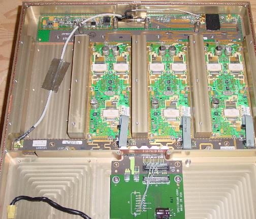
Amplifier Pictures
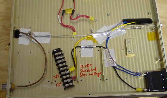
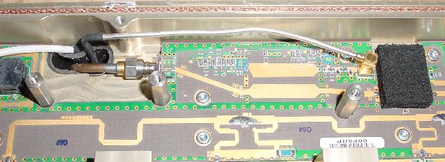
The above photo shows how I wired the DC connections. Notice that I ran the +26 VDC through the existing circuit breaker to take advantage of its protection for the amplifier. The N connector on the bottom left connects to the RF board using UT-141 coaxial cable. The photo below shows the other end of the UT-141 coaxial cable connected to the RF sampling board. Notice the UT-085 coaxial cable from the sampling board. It goes to the front panel SMA connector which has a 50 ohm load attached to it. This is the port you can use to, for example, check the RF output on a spectrum analyzer. By determining its coupling, it could also be used to measure output power. A guess would be -30 dB coupling, but that is only a guess. I have not yet measured it. The resistors used in the DC-DC circuit are still in place though not connected. I didn't have the correct tool to remove them, so they got abandoned in place.
This next picture, above, is a close-up of the original but modified DC distribution board. Notice the two HEAVY black wires that are grounded. These are original wires pulled off the DC-DC converter board. The blue wires going to the other side are the +26 VDC wires. I used two in parallel making sure they were the same length. The yellow wire is the +12 VDC bias voltage that is turned on during transmit. Also notice the 3 leads pulled out of the control bundle in the top right that go to a trace on the PC board that can be seen under the PC board heading to the yellow wire terminal. Again, that is switched on to transmit and off to receive.
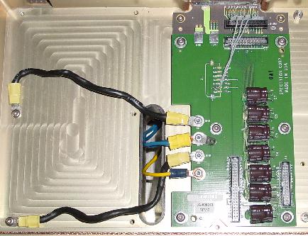
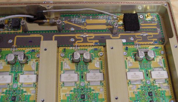
The photo above shows the 3 RF boards with the combiner at the top. The DC distribution board can be seen at the bottom of the photo. The white Teflon coaxial cable is the RF input cable that goes to an SMA connector at the rear of the amplifier. You can see that I used the aluminum tape to hold all the wires down. This can be found in a Home Depot type store in the section where they have galvanized sheet metal air ducts. It is used to seal the pipe sections together, cover holes, and in this case provide a good tight hold on the cables while offering some level of RF isolation on the DC power leads.
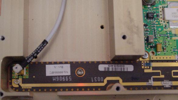
The photo above shows the 3 RF boards, combiner and the RF sampling board. Notice that there is a piece of microwave absorption material over the sampling board. This was put there by Spectrian so I left it in place. I suspect you might see some sort of oscillation if it was removed so I strongly suggest leaving it in place.
Here is a close up of the RF input cable from the rear panel feeding into the power splitter to drive the amplifier. I used the Teflon cable since I had lots of it around with the proper connectors already installed. If memory serves me, this is a SMC push on connector. A cable comes in the amp that might also be useful but it is not long enough to go to the back panel since it only comes from the next board over, which has been removed.
This last photo is a close up of the RF section. One XRF286 driving a pair of the same in each of the 3 boards. Do not touch anything on these boards as no adjustment is needed.
Copyright, NR6CA, 2003, 2008 - All Rights Reserved
Knowledge is Power
