Overview
This is a device to prevent the reception of the Al-Jazeera Arab satellite television "news" channel on Digital Broadcast System (DBS) Ku-band (12.2 - 12.7 GHz) receivers. In the U.S., these signals are transmitted from the ECHOSTAR series of satellites and the one of the propagators of this filth is DISH Network (channel 645).
Imagine... take all the evil television stations, ABC, CBS, NBC, CNN, MSNBC, BBC, CBC, PBS, G4TechTV and combine them into one giant evil station. Now imagine that one evil station is owned, ran, and financially backed by camel-humping, moon-rock worshiping serial killers and terrorists (a.k.a. Arab Muslims). Yes, it is that evil. They use fake pictures, and fake blood, with their fake reporters (intelligence officers) to make fake news reports. You would think that modern, educated people would not fall for this propaganda, but there are alot of stupid people out there. Just look at today's $2600 Magazine readers, Slashdot/Digg posters, Democrats, Eurosavages, movie stars, etc.
The jammer works by generatoring a tunable, low-power, wideband noise (or video) signal between 1.52 and 1.59 GHz (1520 - 1590 MHz). This RF noise signal is then sent to a Hittite Microwave Corp. HMC444LP4 SMT GaAs MMIC x8 Active Frequency Multiplier. This IC "multiplies" the signal eight times. Example: a 1.525 GHz RF signal becomes 12.2 GHz. This allows us to work with much lower frequencies, which are easier to handle, until the last steps of the jammer. Next, the signal is sent to a RF Micro Devices NBB-400 GaAs MMIC Amplifier. This amplifes the new 12 GHz signal by around +10 dB, for a final output power of around +13 dBm (20 milliwatts). This is then sent to a homebrew "can" antenna made from a piece copper plumbing pipe. When placed near a DBS receiver's dish antenna, the jammer overpowers the satellite's already weak signal, preventing reception.
Block Diagram
RF Generator
This is the heart of the jammer. This part takes a standard NTSC video signal, like the output from a VCR, mixes it with a DC voltage offset (which is tuned manually), and then applies it to the Voltage Tune line on a Micronetics M3500-1324 Voltage Controlled Oscillator (VCO). The VCO's output frequency is between approximately 1.5 and 1.6 GHz, and is set via the Coarse and Fine 10-turn tuning potentiometers. Observe that the VCO's output frequency is correct by connecting the RF output to a frequency counter or spectrum analyzer. Set the VCO to output a RF signal which is equal to the Ku-band satellite downlink frequency you wish to jam, divided-by-8. That is, if you want to jam 12.428 GHz (DBS, transponder 15), set the VCO to output approximately 1.5535 GHz. Since this frequency is set manually, and without any PLL synthesizer, it will drift in frequency a little bit. This slight drift is irrelevant in a wideband jamming system, but you may need to tweak the frequency occasionally to keep the jamming "in-band".
The Video Input signal can be the standard baseband video output signal from a VCR, video camera, TV, CATV converter, Nintendo, etc. It can even just be random noise or Al Gore MP3s. The VCO's resulting RF output will be Frequency Modulated (FM) with whatever comes in the Video Input so wideband, random jamming signals, like NTSC video, really work quite well. The video pre-emphasis and high-frequency compensation network (those caps and resistors in the Video Input) are not really needed, but are useful if you wish to turn the jammer into an actual, real FM TV transmitter.
x8 Multiplier
The most important RF part of the jammer is the x8 active frequency multiplier. This device takes the 1.5 - 1.6 GHz RF signal from the RF generator section and multiplies it eight times to approximately 12.0 - 12.8 GHz. Fortunately, there is no need for any complicated microwave RF construction of this device. Hittite Microwave sells a fully complete and operational evaluation board ($149) for the HMC444LP4 frequency multiplier. The evaluation board has two SMA connectors for the RF input and output, so you may need some high-quality connecting coaxial cables. The evaluation board needs +5 VDC at only a few milliamps.
You'll note that for this particular application, we are running the HMC444LP4 out of frequency specification, it will still work though.
RF Amplifier
The next most important part is the 12 GHz RF amplifier. It is also a good idea to use a pre-made evaluation board for this amplifier, as making a stable 12 GHz RF amplifier from scratch is extremely difficult. A good compromise between price and performance is the RF Micro Devices NBB-400 MMIC amplifier. This device will amplify the x8 frequency multiplier's RF output (12.0 - 12.8 GHz) by about 10 dB. The final RF output power will be approximately +13 dBm (20 mW). There can be significant RF loss if the interconnecting cables, connectors and/or adapters are of low-quality or the coax runs are too long. Richardson Electronics sells a fully complete and operational NBB-400 evaluation board for $35. This board also uses SMA connectors for the RF input and output. Refer to the NBB-400's datasheet for information on changing the bias resistor for operation at +12 VDC (change to 162 Ohms, 1/2 Watt).
Again note that for this particular application, we are running the NBB-400 out of frequency specification, it will still work though.
Antenna
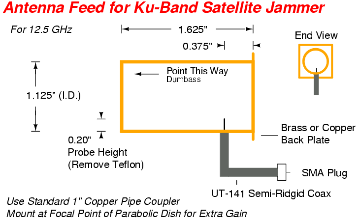
A simple 12 GHz "can" antenna can be made from a 1.625 (1-5/8) inch long piece of 1.125 (1-1/8) inch diameter copper pipe. A standard one inch diameter "Full Slip Repair Coupling" (that's what it says at the store) will work perfect. One inch diameter copper pipe is really 1.125 (1-1/8) inches in diameter. A small piece of hobby brass or copper sheet will be needed to enclose the back end of the "can". Be sure to solder it fully around the outside edges of the copper pipe. The actual antenna feed is nothing more that a short 0.2 inch probe made from the exposed center conductor (minus the Teflon) on a piece of UT-141 semi-rigid coaxial cable. You solder the UT-141 directly to the copper pipe. Add a SMA plug to the other end of the UT-141 to connect to the NBB-400's RF output SMA jack. For an extra 30 dB of gain or so, mount this entire contraption at the focal point of a surplus DIRECTV or DISH Network parabolic satellite dish. Scrap satellite dishes can be found in the dumpster at your local cable company.
For a more "professional" antenna feed, get ahold of a WR-90 to N-connector waveguide adapter and a high-gain WR-90 waveguide horn antenna. The waveguide adapter is machined to much tighter tolerances than anything which can be homebrewed, so the insertion losses will be alot lower and the gains higher. All this, of course, increases the cost. You can often find good deals on waveguide sections at your local hamfest.
Pictures
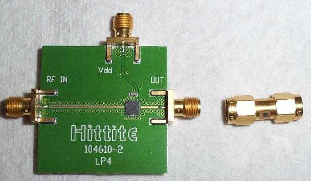
This is a picture of the complete HMC444LP4 evaluation board. The 1.5 - 1.6 GHz RF input is on the left, the 12.0 - 12.8 GHz RF output is on the right. The top SMA jack is for the +5 VDC power line.
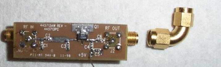
This is an old Watkins-Johnson RF amplifier used for testing. It has very poor specifications at 8+ GHz. The RF Micro Devices NBB-400 is alot better choice. The 12 GHz RF input is on the left and the RF output is on the right. The +5 VDC power is applied on the little wire.
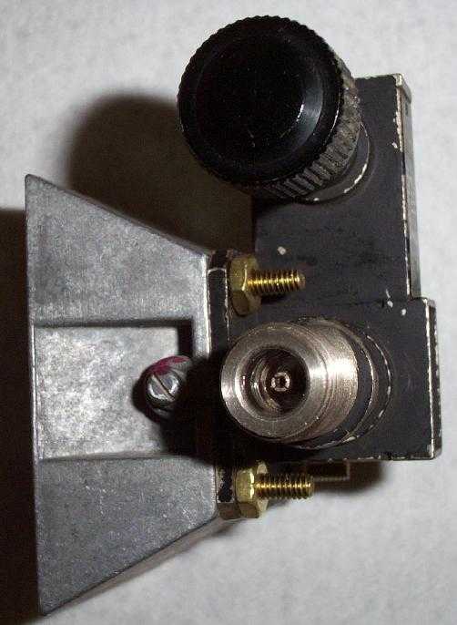
This is a picture of a WR-90 to N-connector waveguide adapter connected to a small WR-90 horn. Note that this particular adapter has a diode detector tap (the large black knob) for measuring RF power. An adapter which has an internal diode detector is not necessary, but does help in verifing the final RF output power. Also note the use of brass mounting hardware to connect the horn antenna to the adapter. The use of hardware which does not contain steel (brass, stainless steel) is highly recommended.
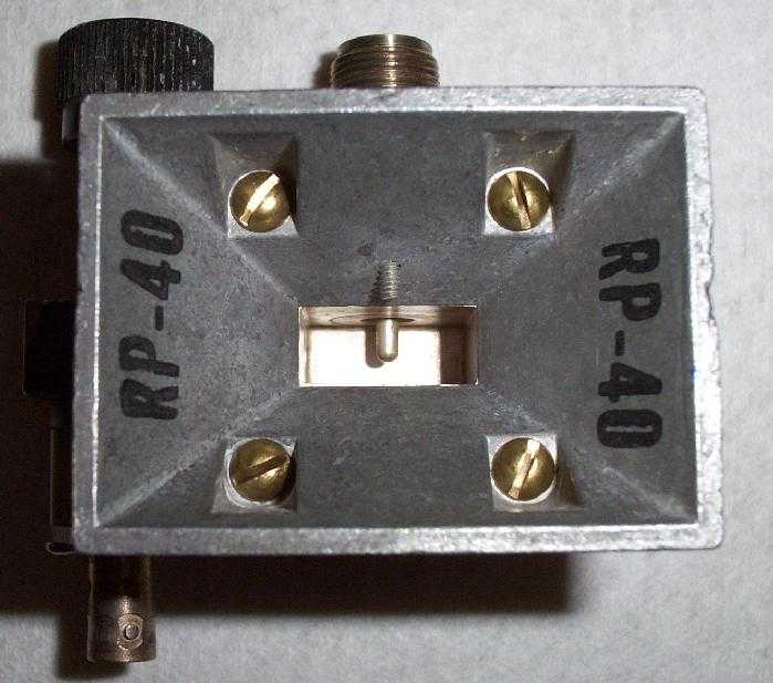
Looking down the horn antenna into the waveguide adapter. The little silver probe mounted in the back of the waveguide is the actual antenna. The little screw on top of the horn is for adjusting the horn's frequency response, leave it alone. The BNC connector on the left is part of the diode detector.
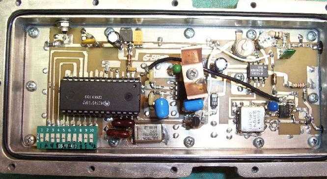
This is the RF generator used for testing. It's actually a modified 1.2 GHz (23 cm) Amateur Television (ATV) video transmitter. The PLL synthesizer section and the MMIC RF amplifier after the VCO are not needed. The video input is on the top right connector and the RF output is the bottom right connector.
Schematics and construction details of the GBPPR 1.2 GHz (23 cm) ATV Video Transmitter are available here.
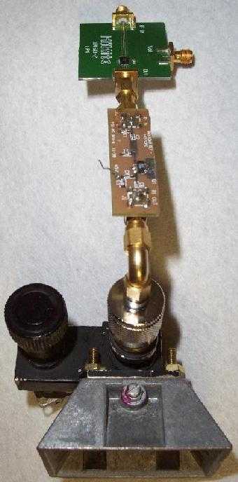
An overview of the x8 frequency multiplier, RF amplifier, waveguide adapter, and horn antenna connected together. Mount this, gently, at the focal point of a parabolic dish for alot more (around +30 dB) gain.
Bonus! Set the RF generator to output a frequency of around 1.315 GHz and this device can be used to jam X-band (10.525 GHz) police speed radars or even to jam certain automatic door openers.
Datasheets & Notes
Schematic
- Al-Jazeera Satellite Reception Jammer Schematic 1.5 - 1.6 GHz Exciter Section