Overview
It seems like there are thousands of corrupt politicians and judges out there who are refusing to help the common man in their fight against liberal propaganda, illegal alien crime, and Marxist brainwashing in our school systems. Of course, these same politicians and judges will only live in rich, majority-white, gated communities and will only send their kids to elite private schools. This is to further help isolate themselves from the disease, decay, and crime brought about by genetically inferior invaders from third-world countries.
Judges are even now giving non-U.S. citizens "constitutional rights." Scary stuff... This is a standard liberal attempt to weaken the U.S. constitution by giving everyone the same rights (i.e. Marxism). Usama bin Laden could now probably sue the NSA or CIA if they were to listen in on his telephone calls, and you sure as hell know the ACLU won't be backing the U.S. taxpayers on that one!

Don't think there is a way for the common man to fight back?
Well, you can...
The one good thing about third-world trash and illegal aliens is that they'll march together in the streets whenever their "rights" are threatened. But, just don't count on them marching for your rights, or even the rights of people in the military.
Just imagine if the next time the third-world trash and illegal aliens are having one of their little demonstrations, someone were to open up with a few full-auto bursts from a MG-42.
That would be terrible now, wouldn't it?
There's just one problem, though. Since cellular phones are so prevalent today, it would probably be only a matter of seconds before some traitor called 911.
But what if the cellular phone service in the entire area was disabled? Heh.
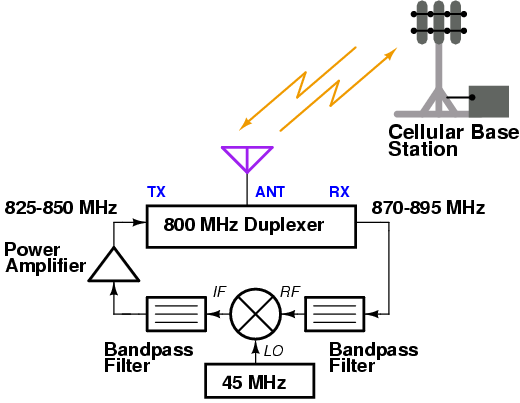
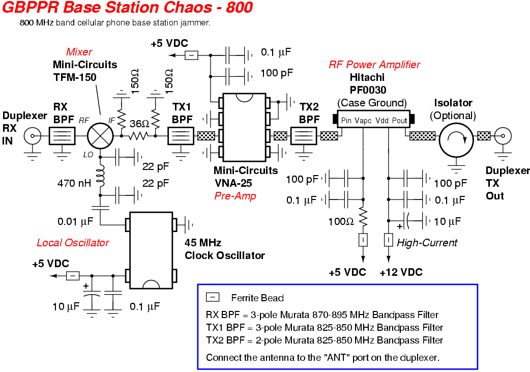
This particular device is a based around a slight modification to the cellular phone jammer in GBPPR 'Zine, Issue #49. Instead of mixing the cellular handset's transmitted frequency with a 45 MHz signal to jam the downlink, we'll reverse this process.
Now, the base station's transmitted output frequency (870-895 MHz) will be mixed with a 45 MHz local oscillator signal. The new, lower IF frequency (825-850 MHz) will be filtered, amplified, and finally rebroadcast. The cellular base station will now essentially be jamming itself. Everytime the base station's transmitters go on the air, the base station will have its receiver's jammed by its own transmitted signal.
To use this jamming device, place the antenna as close to the cellular base station as possible, or at least somewhat within radio line-of-sight. Cellular radio sites use multiple directional sector antennas, so you may have to build several of these devices to disable cellular phone service in a large geographical area. Receive pre-amplifiers can be added to the RF input to the mixer to help extend the "receive' range slightly.
A similar device can also be constructed to disable cellular phone systems in the 1.9 GHz PCS band. You'll just need to replace the duplexer, filters, RF power amplifier, and antenna with ones which cover that frequency range. You'll also need to replace the 45 MHz clock oscillator with one that operates at 80 MHz.
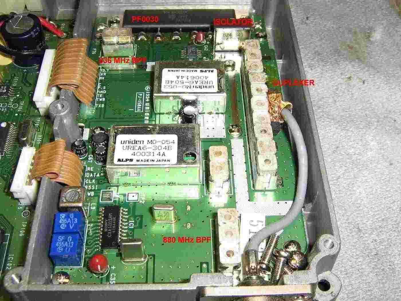
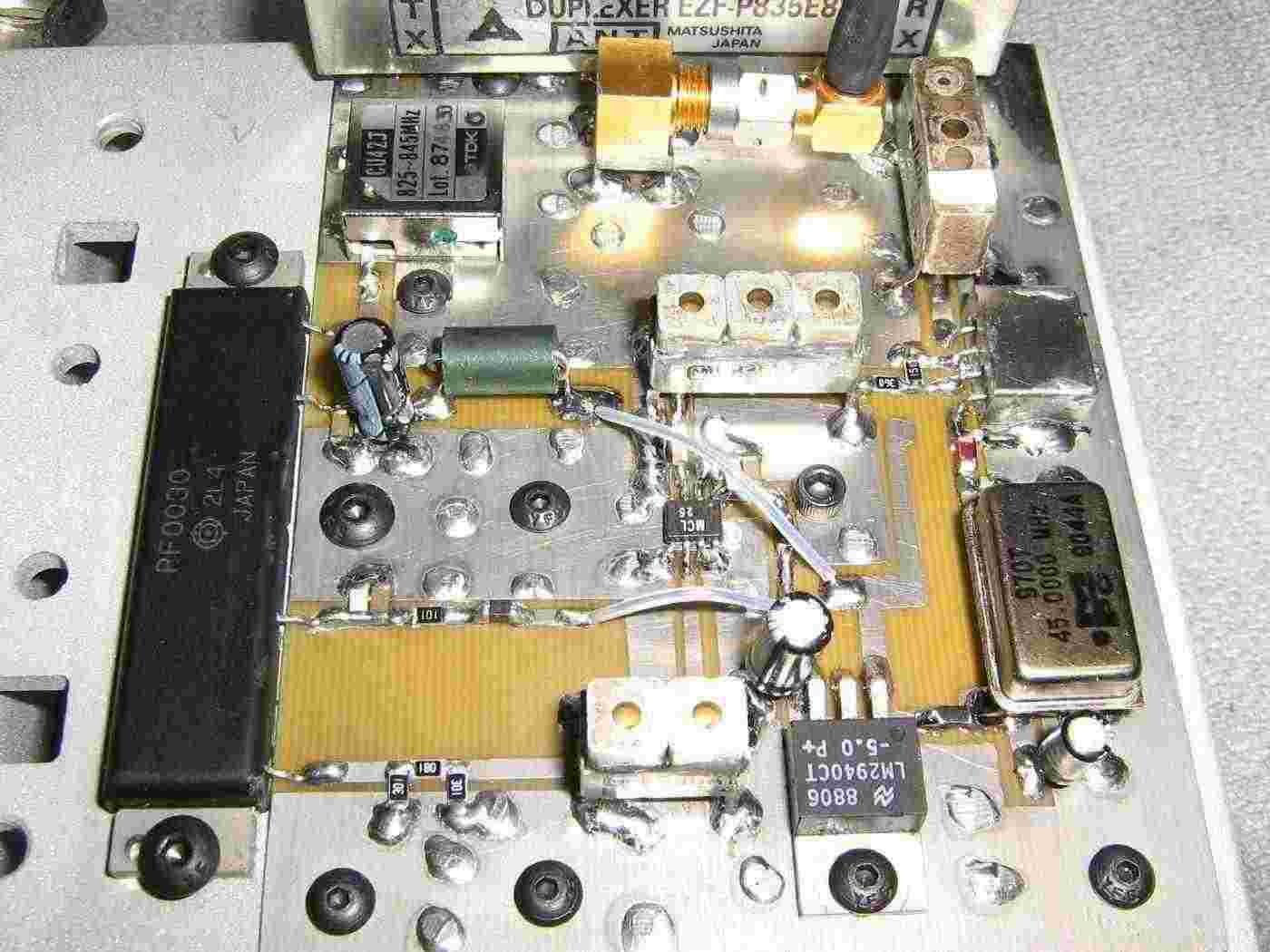
This is the kind of old cellular phone you'll want to look out for when salvaging for RF parts.
Shown above is an Uniden CP1700 analog cellular phone (AMPS). It uses the common Hitachi PF0030 RF power amplifier module, and also has nice, non-surface mount Murata bandpass filters on both the transmit and receive sides. It also has a very nice antenna duplexer and even a protection isolator on the RF output of the PF0030 amplifier.
Salvage all the parts you can and also keep an eye out for a nice heatsink to mount the RF amplifier and jammer PC board to.
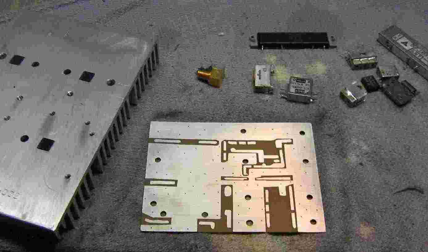
You'll need to make sure the PC board is constructed with a large RF ground plane and lots of ground vias.
Starting the PC board component layout.
Layout your board however is most convenient, making sure any components carrying a RF signal have a good ground plane and strong solder connections.
The PF0030 should also have a very thin layer of heatsink compound underneath it before mounting. Be sure not to overtighten the mounting screws for the RF amplifier module, or its internal substrate material can crack.
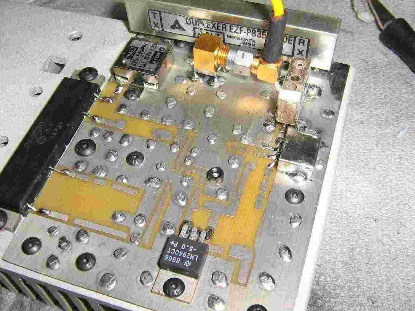
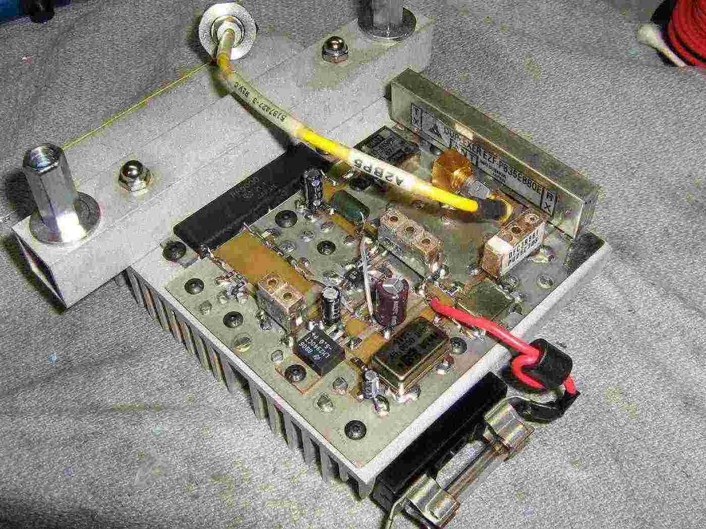
Jammer PC board completed overview.
The antenna input connector is a SMA jack going to the "ANT" port on the duplexer.
The "RX" port on the duplexer (870-895 MHz) is sent to a 3-pole Murata 880 MHz bandpass filter and onto the RF input port on a Mini-Circuits TFM-150 mixer.
The LO input port on the mixer is feed with an impedance matched 45 MHz clock oscillator signal.
The IF output port on the mixer is then feed to a 6 dB attenuator pad and a 3-pole Murata 836 MHz bandpass filter. This then feeds a Mini-Circuits VNA-25 MMIC amplifier to increase the signal levels slightly. This is then sent through a 2-pole Murata 836 MHz bandpass filter. There is an optional 3 dB attenuator pad just before the input to the Hitachi PF0030 RF power amplifier module.
The PF0030 amplifier module has a constant +5 VDC on the power control line (Vapc) and +12 VDC on the Vdd line. The output of the PF0030 is sent through an optional isolator to protect the power amplifier from any impedance mismatches or even a missing antenna.
The isolator finally feeds the "TX" port on the duplexer, and the signal is sent back out through the antenna port.
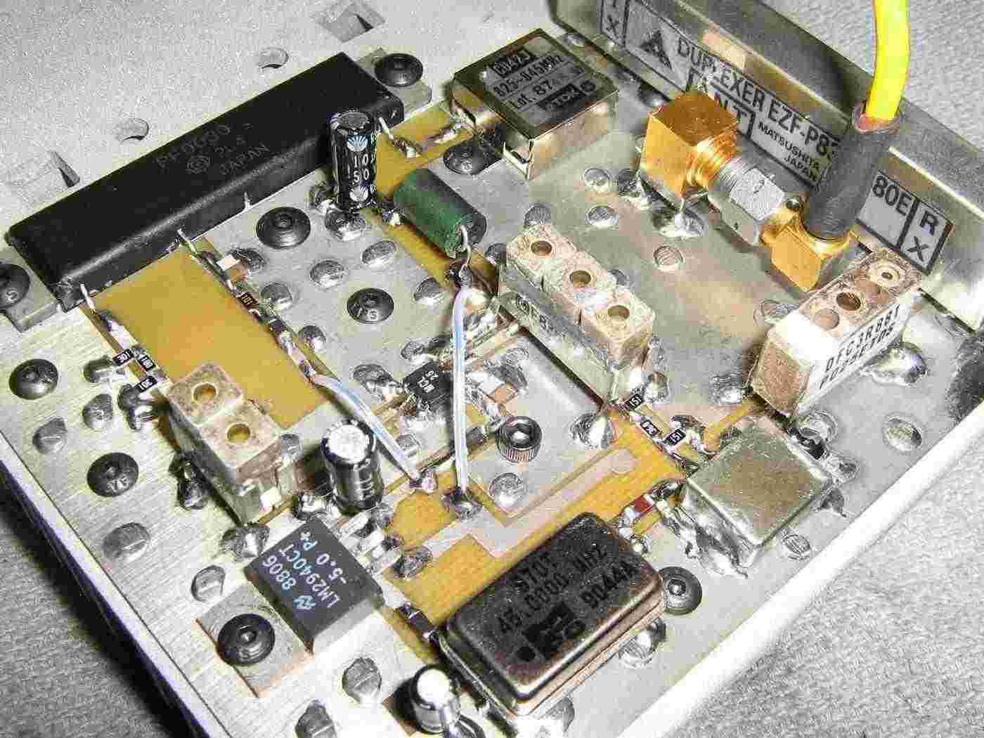
PC board layout alternate view.
Completed Base Station Chaos jammer.
A fuse holder and a 10 amp fuse were added to the side of the heatsink. The jammer itself will be mounted using a small piece of aluminum square tubing and some 1/4-inch couplers and hardware.
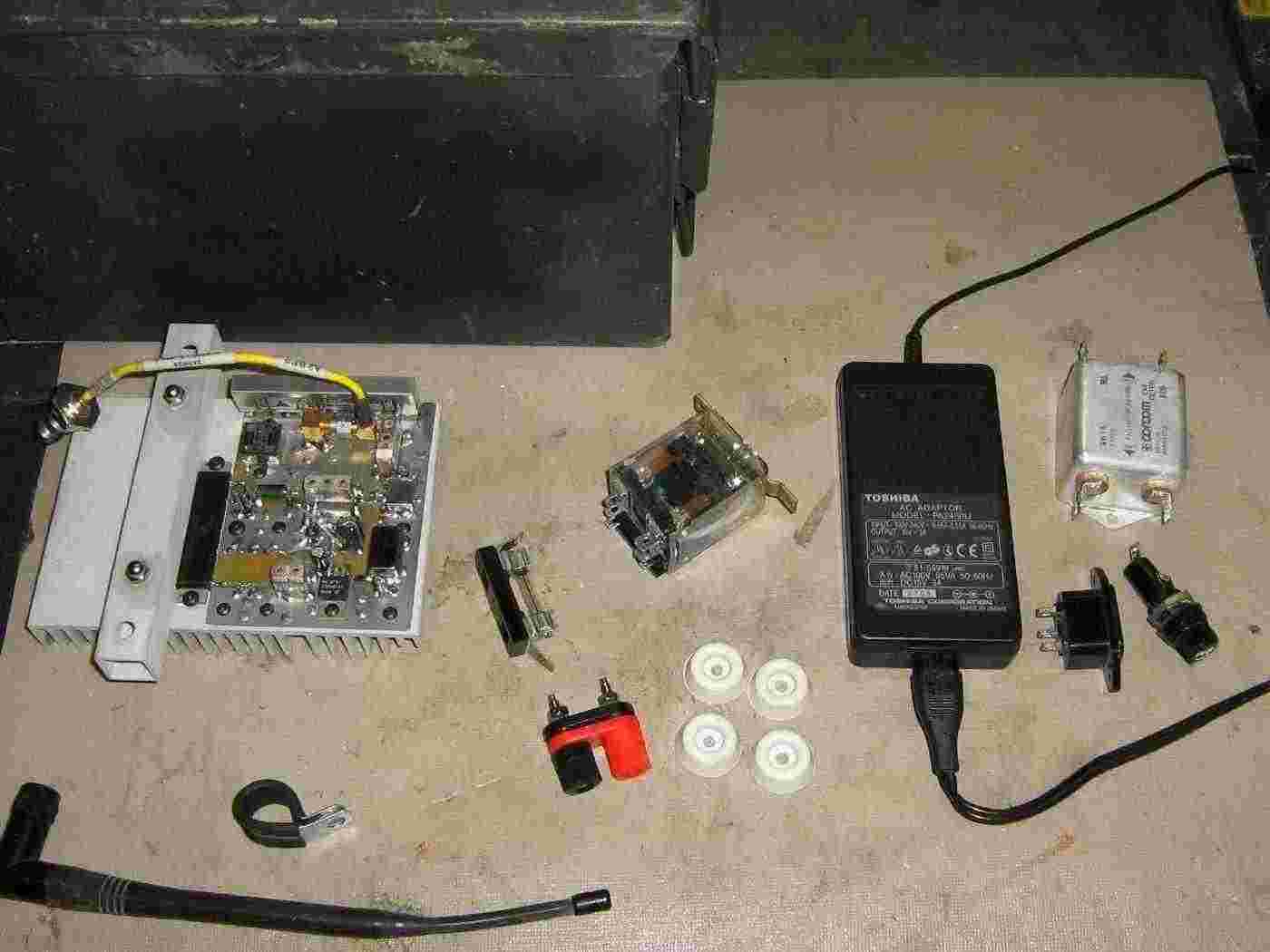
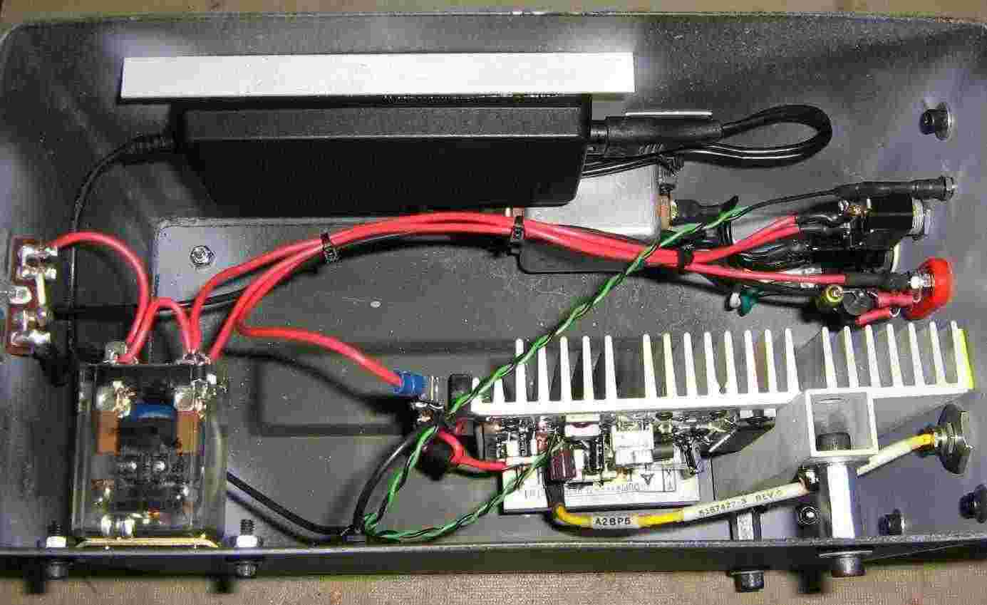
Case overview.
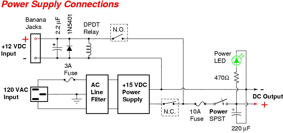
For this project, the power source will be both AC and DC. An old +15 VDC, 3 Amp laptop switching power supply will be the main power supply, and a DPDT relay will switch between the AC or DC power when an external +12 VDC power source is applied.
The incoming 120 VAC will be passed through an AC line filter, fuse, and a power switch.
The (optional) incoming +12 VDC line will come in through panel-mounted banana jacks.
Front-panel overview.
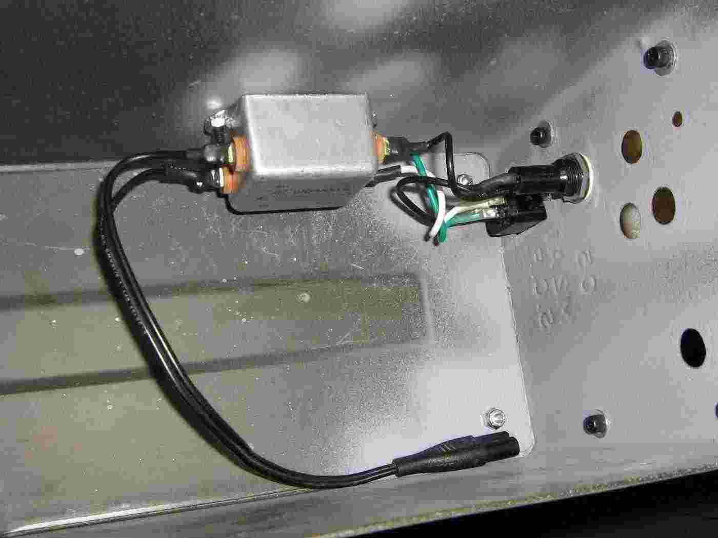
Incoming 120 VAC from a standard IEC connector is fed through a fuse and onto the AC line filter.
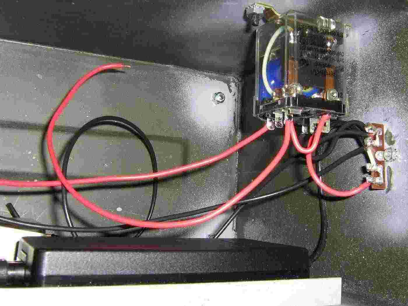
Power select relay.
The default position is to power the jammer from a 120 VAC wall-wart power source, but as soon as an external +12 VDC power source is applied, the relay switches over, disconnecting the AC side.
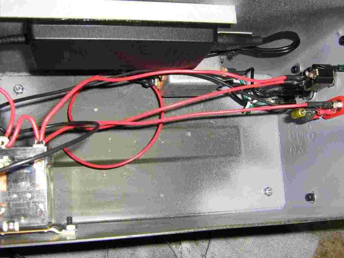
Case internal view with completed power supply wiring.
The +15 VDC laptop wall-wart power supply is epoxied to a small piece of aluminum bracket and secured to the side of the case. All the solder connections should be covered with heatshrink tubing for protection.
Finished overview.
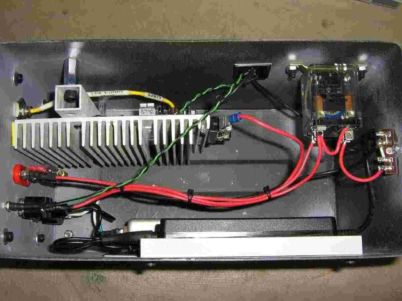
Alternate view.
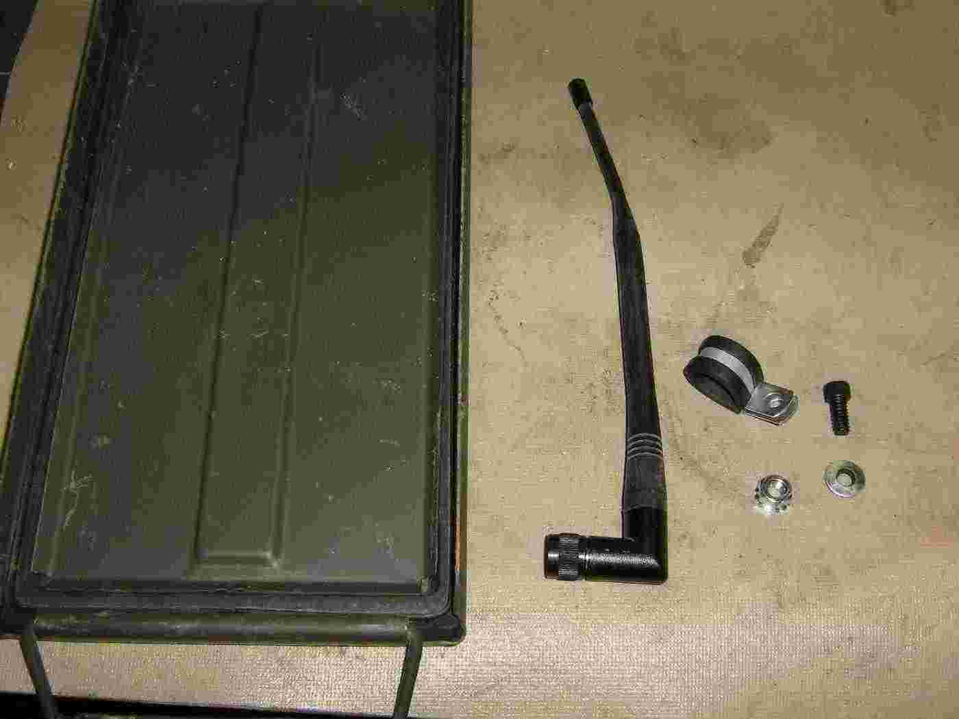
Make a simple antenna holder using a padded gas line clamp and some 1/4-inch hardware.
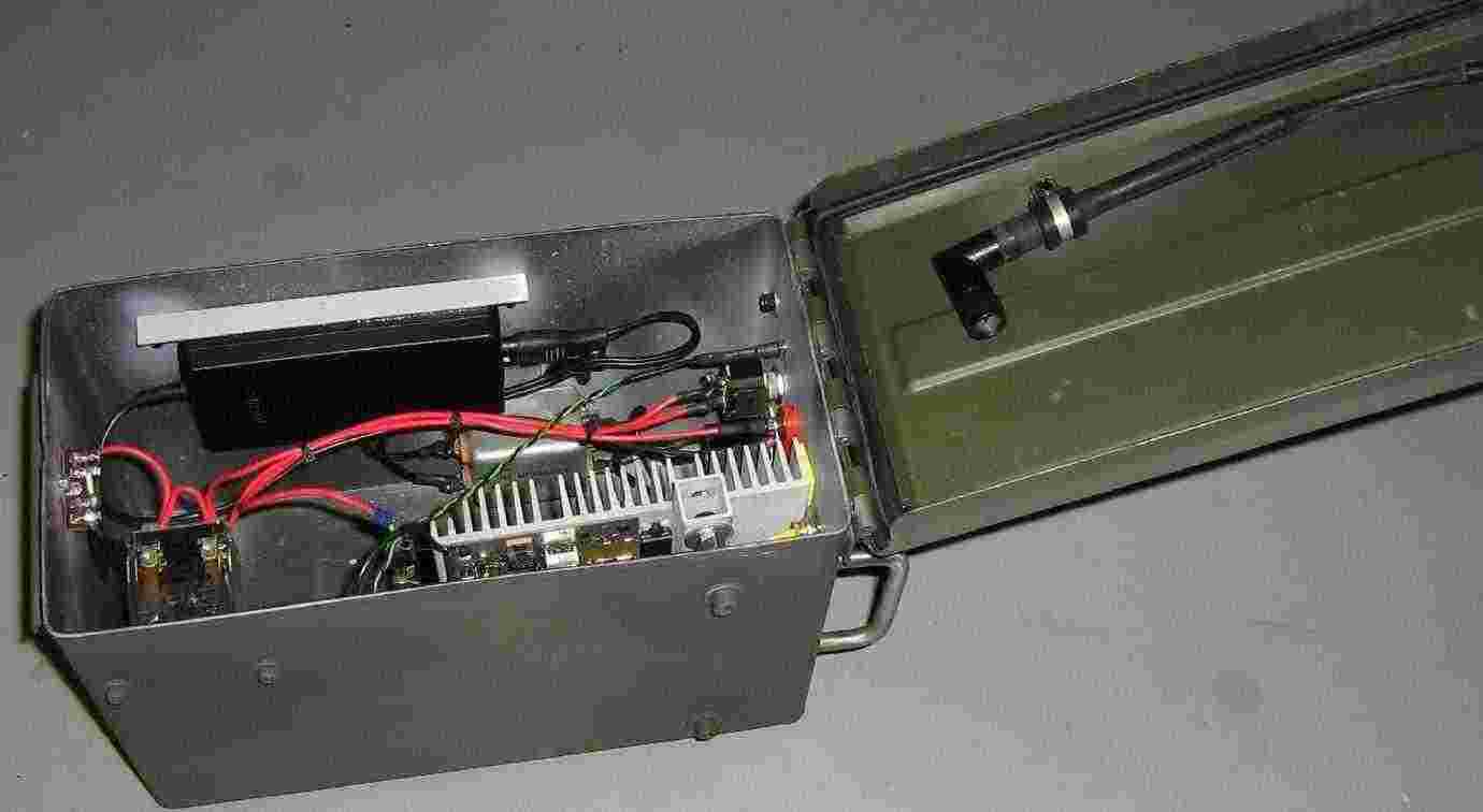
Internal overview showing the antenna holder attached to the lid.
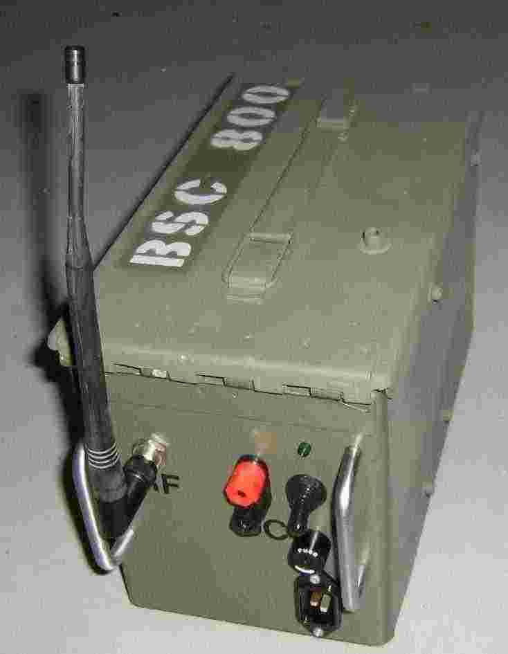
A cellular phone company's worst nightmare.
On the right-hand side are the 120 VAC input, fuse holder, power switch, and a power indicator LED.
In the middle are the banana jacks for +12 VDC input.
On the left is the TNC antenna jack.