A doppler stethoscope is used for the non-contact analysis of mechanical vibrations. This is useful for remotely analyzing non-metallic objects such as backpacks or briefcases. The doppler stethoscope detects the physical motion of an object, such as the gears of a clock, and is even sensitive enough to detect the motion of flowing electrons. A low-noise audio amplifier amplifies and converts these weak doppler-shifted signals and sends them to a pair of headphones. A common use for a doppler stethoscope is during Explosive Ordinance Disposal (EOD). If a terrorist leaves a backpack on a bus or train, you can quickly analyze it for any suspicious ticking noises. It can also be used during TSCM sweeps to search for hidden electrical devices in upholstery, ceiling tiles, plants, etc. Hidden mechanical tape recorders can be detected this way.
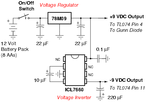
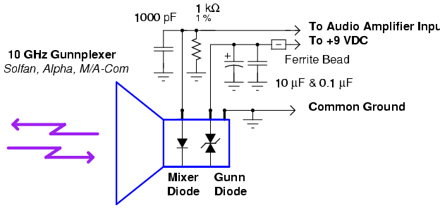
The basis for this version of a doppler stethoscope is a 10 GHz Gunnplexer from an old Solfan intrusion alarm. These can often be found at ham radio swapfests for as little as $5. Failing that, you can also find 10 GHz Gunnplexers in old automatic door openers. 24 GHz Gunnplexers will also work, and will be physically much smaller, but those can be difficult to find. The audio amplifier is based around the common TL074 quad op-amp feeding a LM386 headphone driver. Everything runs off eight "AA" batteries or around +12 VDC.
Sweep the stethoscope around the package you wish to check. Be sure to cover every possible angle. The scanning distance from the package should not exceed about one foot, closer is better. You also should rotate the stethoscope 90° and re-sweep the package. You should practice ahead of time. Practice sweeping cellular phones, LCD or LED displays, mechanical clocks, tape recorders, etc. A good practice test is pointing the doppler stethoscope at a fan or even a CD-ROM drive. You'll hear the gears of the CD-ROM drive controling the door, and then you'll hear the CD start spinning. Also note that you can detect the 60 Hz hum from fluorescent lights quite easily. External audio filtering may be used to "peak" the signal you are interested in. Occasionally point the doppler stethoscope at the ground to compare what you are hearing with a "clean" signal.
Try to build the Gunnplexer and audio amplifier board into shielded or metal container. The horn antenna should be exposed or covered with a very thin plastic sheet to protect it. The Gunnplexer's die-cast body should be well grounded. Try to use 1% tolerance, metal film resistors in the audio amplifier section. These offer the lowest noise. The LM386 audio driver is only capable of driving low-impedance (8/16/32 ohms) headphones. Avoid high-impedance (600 or higher ohms) headphones. A step-up matching transformer can be used to match high-impedance headphones, if needed. You should also always use fresh batteries. The Gunn diode's bias voltage is quite critical and can be damaged if the voltage is too low. Avoid using a single 9 Volt battery or any carbon-zinc batteries. The mixer output signal should be routed using a small piece of coax (RG-174) or shielded wire.
Bug Alert! This design is still experimental! You may wish to experiment with the amplifier gain and low pass filtering to suit your particular need. Also, there can be switching noise breakthrough on the 7660 voltage inverter line. To cure this, use a switching regulator which oscillates above 20 kHz.
Top view of a Solfan 10 GHz Gunnplexer. There are five solder tabs on this particular version. Starting from the left, is the Mixer Diode Output. This should have a parallel 1 kohm resistor / 1000 pF capacitor soldered to ground across it. This acts as a DC return for the bias voltage the Gunnplexer places on the mixer diode. The 1000 pF capacitor shunts any stray RF signals to ground. The two tabs to the right are Ground and an Isolated tab. The isolated tab isn't used in this application, but is useful for hanging extra components off of. The tab to the right of those is another Ground tab, and the last solder tab is for the Gunn Diode Bias voltage. This will be around +9 Volts. Both the mixer and Gunn diodes are extremely static and shock sensitive, so be careful around them. If they blow - you are basically screwed.
Alternate view. This particular model was retuned back into the ham band (10.2 GHz). The exact frequency isn't important, and will most likely be around 10.525 GHz when you first receive it. The metal mounting plate might vary with the particular Gunnplexer model you use.
Inside the horn antenna. Be sure to use brass or stainless steel hardware for mounting the horn.
This is an Alpha 10 GHz Gunnplexer from an automatic door opener. The solder posts from left-to-right are: Mixer Diode Output, Ground (bottom post), and Gunn Diode Bias.
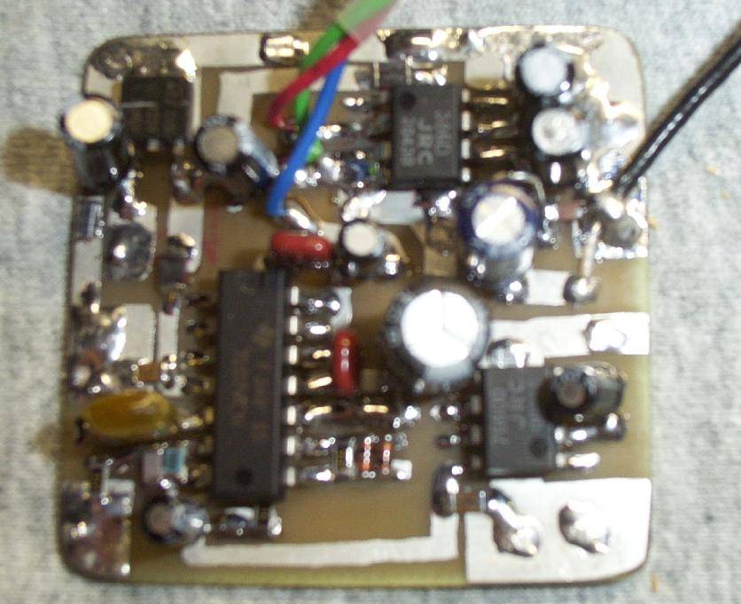
Low-noise amplifier board. Only picture available. The 78M09 is on the upper left. The TL074 is the large IC in the middle. The ICL7660 voltage inverter is on the lower right. LM386 audio driver is above that. Red/Green/Blue wire bundle is for the volume control.
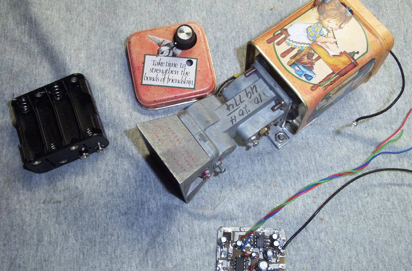
Overall view before final assembly. The low-noise amplifier board is mounted into an old cookie tin. It is mounted to the back of the Gunnplexer via rubber standoffs.
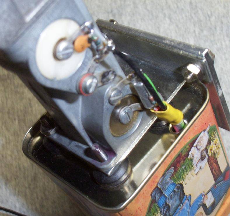
Close up view of the Gunnplexer's connections and mounting hardware. Note the rubber washers. These are actually faucet washers. They make great stand-offs.
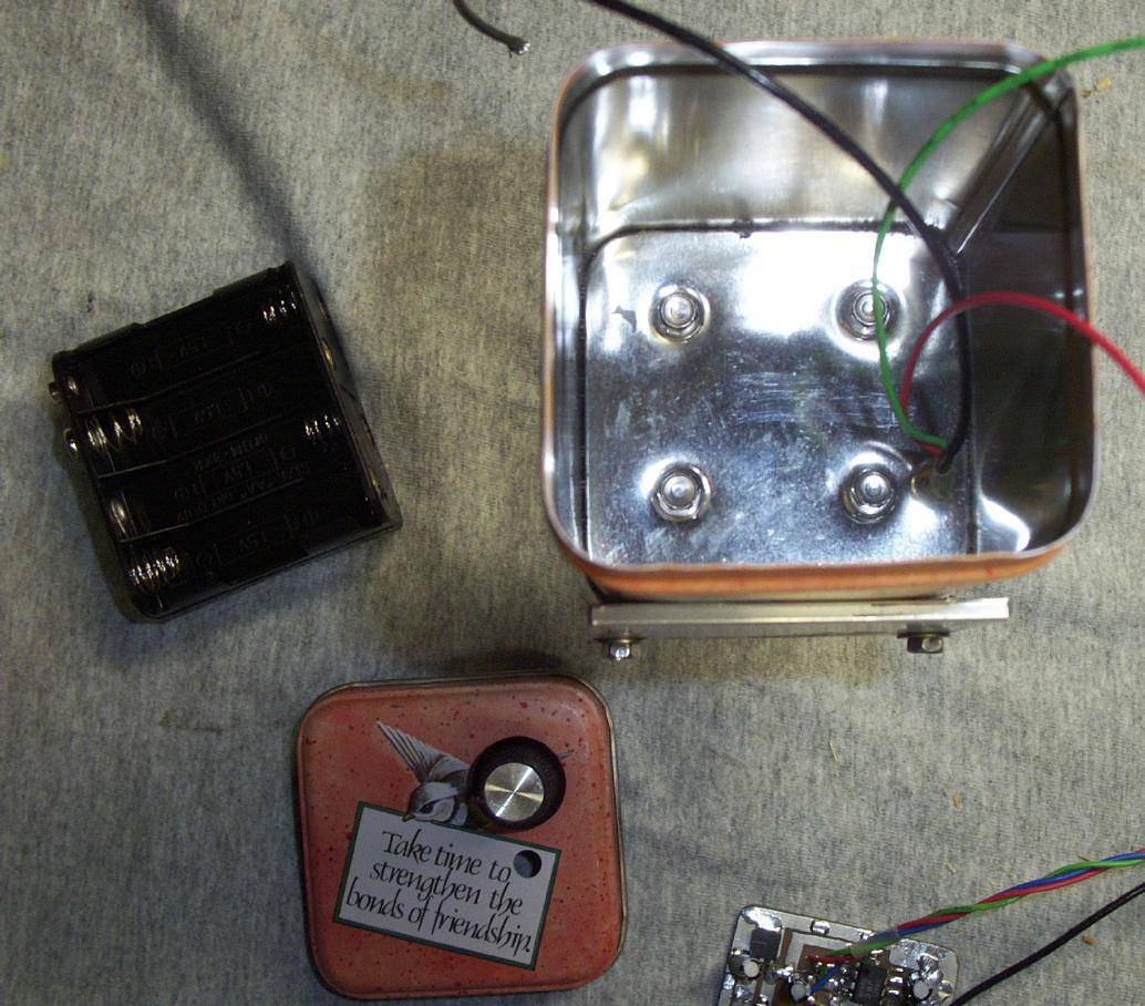
Inside the cookie tin. Battery holder is the black thing on the left.
Completed doppler stethoscope. Volume potentiometer has a built-in on/off control. Try to pick a cookie tin that isn't... ahh... so gay.
Alternate side view.
Inside the cookie tin case on the completed doppler stethoscope. A piece of art foam is on the bottom of the tin to protect the battery pack.