| Laser Bounce Listening Device |
The Laser Listener
Originally published in Radio Electronics Magazine, October 1987, by Richard L. Pearson
Use a light beam to listen in to anything, anywhere, anytime...
Breaking and entering to plant a listening device is one way to "bug" a room. Unfortunately, it can earn you a long jail term. A better and safer way to bug a room is to use a laser beam to eavesdrop on a window from across the street.
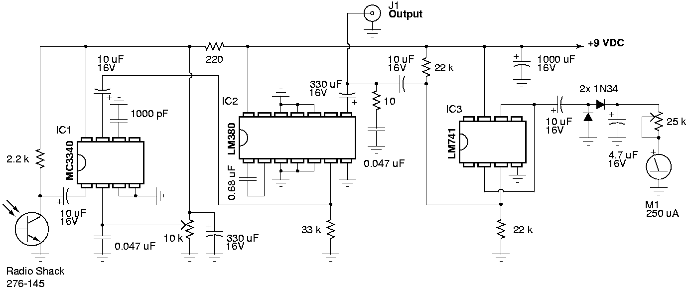
The sound waves generated by nearby conversation will cause the glass in a window to vibrate very slightly. If a laser beam is bounced off the window, its reflection will be modulated by the vibrations. All that's needed to hear what is being said is a demodulating device that extracts the audio from the reflected laser beam. That technique is used by sophisticated "surveillance experts," but you can easily duplicate that feat by using a hobbyist's laser and the inexpensive Laser Listener demodulator shown in Fig. 1. If you need something a little more sophisticated, it can be made part of the riflescope aimed laser-bug system that is shown in Fig. 2.
![[fig1]](fig1.jpg)
Fig 1
(Improved PNG Version)
![[fig2]](fig2.jpg)
Fig 2
Early Light-Wave Communications
Communication using a modulated beam of light isn't a new idea. In the 1880's, Alexander Graham Bell experimented with something he called a photophone; a device that modulated a beam of sunlight. It had a mouthpiece that concentrated sound energy on a reflecting diaphragm, which, in turn, modulated a beam of sunlight that was aimed at the diaphragm. When a remote receiver consisting of a photovoltaic cell and a sensitive earphone was positioned in the beam, the voice could be heard clearly from the receiver. The aiming problems presented by the movement of the sun, and the interruptions due to clouds and night, probably prevented the commercial exploitation of the device.
But by using coherent light - such as that produced by a continuous-wave laser - the principles used by Bell's device may again be applied in a meaningful way. After all, terrestrial lasers aren't influenced in any way by sunlight or clouds. And perhaps more important, unlike acoustic sound-detection devices, lasers aren't usually subject to interference originating between the sound source and the receiver.
For example, remote sound-pickup devices in the form of directional microphones have been available for many years. Unfortunately, any sound generated between the listener and the sound source usually renders the device useless because the interference is heard at the receiver, and it can be even louder than the source. On the other hand, lasers are not sensitive to sound of any kind between the source and the receiver. However, lasers may be subject to other kinds of interference: For example, AC-powered incandescent lights can produce a hum; gas discharge devices such as fluorescent, mercury, sodium vapor, and neon lights might produce a buzz; and direct sunlight might swamp the laser detector device. Also, where unusually long distances are involved, air currents can add flicker to the laser beam, which on windy days can result in a noise that is similar to that of blowing into a microphone. (But even though sensitive to some kinds of electrically-generated noise, laser-listening devices have an advantage: They can seemingly hear through walls or closed windows, and even selectively monitor only one window of a building from several hundred feet away.)
Commercially available laser sound pickups use a laser device having an output in the infrared region. Because infrared is below the visible portion of the light spectrum, it cannot be seen by humans. However, some commercial devices have a power output rating as high as 35 milliwatts. At such a power level there is clear potential for eye damage if someone in the target area unknowingly stares into the beam, or if the laser is operated carelessly by the user.
Laser Basics
Although the details underlying the generation of laser light are beyond the scope of this text, an understanding of some of the characteristics of a laser beam as compared to ordinary light will be helpful in assembling a laser-listener system.
Light is considered to be comprised of packages of energy particles called photons. However, light is also electromagnetic radiation and behaves like radio waves, although at a much higher frequency. The perceived color of visible light is determined by the radiation's wavelength, which is usually given in micrometers. The shorter wavelengths are perceived as violet, the longer wavelengths as red. The spectrum below the visible portion is called infrared; the spectrum above is called ultraviolet.
The light emitted by a conventional incandescent or fluorescent source contains a wide range of frequencies, and the photons are emitted randomly and spontaneously in all directions. On the other hand, in a laser light source the photons are released in one direction, at one frequency, making the laser light highly directional and pure in color. (An analogy would be to liken ordinary light to white noise, while the laser is likened to a sinewave - a single pure tone.) Since all of the light emitted by a laser is coherent (has the same frequency), constructive or destructive interference occurs when two beams of laser light meet at the same place and time (Fig. 3).
![[fig3]](fig3.gif)
Fig. 3
As shown in Fig. 3-a, the beams cancel each other when out of phase (destructive interference). As shown in Fig. 3-b, the beams are additive when in phase (constructive interference). It is the interference between the beams that enables the movement of any reflecting surface to be sensed by a device called an interferometer. An interferometer is a beamsplitter - usually a piece of partially-mirrored glass - that deflects only a small part of a beam aimed through the glass. As shown in Fig. 4, it can be used to reflect both the source and the reflected laser beams so that their phasing or amplitude can be compared by a receiver.
The major problems with using interferometry for eavesdropping is that only a part of the laser's energy is directed at the target, limiting the working range, and the interferometer is sensitive to the diffusion of the sounds target's reflections caused by tremors in the mountings of the interferometer, the laser, and the reflective target. For super-snooping, a direct reflection from the target is preferred because the collimated nature (parallelism) of laser light also allows modulation of the beam to occur just as Bell`s photo-phone modulated the sunlight.
![[fig4]](fig4.gif)
Fig. 4
The Prototype's Laser
Regardless how we choose to eavesdrop, we must start out with a laser, so we' ll cover the prototype laser bug's unit first. It's a Heathkit Model ETS-4200 Laser Trainer, a Helium Neon (HeNe) unit having an output power of 0.9 milliwatts. It has a beam divergence of 1.64 milliradians, which produces a spot of light 1-1/2 inches in diameter at 200 feet. Although 0.9 milliwatts doesn't appear to be much power, it can cause extreme eye damage if allowed to shine or be reflected directly into the eye, or if viewed directly through any optical device such as a telescope, binocular, etc. The beam may be safely viewed only if projected onto a non-reflective surface such as a white sheet of paper.
If you want to keep costs at rock-bottom, or just want the excitement of a complete home-brew project, another alternative is to assemble the helium-neon laser shown in the June 1986 issue of Radio Electronics. Also. if you want to build a laser from your own design, helium-neon tubes are often available from "surplus" distributors.
The Receiver
The Laser Listener's receiver is relatively easy to build and adjust. It is designed to drive a 4 to 20 ohm headphone or speaker, which permits just about any high-fidelity or Walkman-type headphone to be used for monitoring. The circuit shown in Fig. 1, uses a photo transistor (Q1) for a sensor, and has a meter (M1) that indicates the relative signal strength of the reflected laser beam. Because the meter responds only to the amplitude modulation of the reflected laser beam, it is unaffected by ambient light and the relative intensity of the laser beam. An adjustable polarizing light filter can be installed in front of Q1 to avoid swamping of the phototransistor by very high ambient light.
Phototransistor Q1 is an inexpensive type usually called an IR detector, which means that it is specifically sensitive to infrared light. Tests comparing the unit specified in the partlist with other less readily-available and more-expensive devices show no measurable difference in performance in the prototype receiver. No base connection is used for Q1 because the reflected laser light controls the collector current. The audio signal developed across collector load-resistor R1 is coupled by C2 to voltage-controlled attenuator IC1, which has a greater than 30 dB gain variation; It serves as both a preamplifier and as an electronic volume control.
Resistor R2 and capacitor C1 decouple (filter) the power supply voltage to Q1 and IC1. Be sure to take extreme care not to eliminate or accidentally bypass the filter because that will cause unstable operation. The gain of Q1 and IC1 is too great to permit non-decoupled operation from the power supply.
The output from IC1 is fed through C4 to amplifier IC2. Resistor R4 and capacitors C5 and C7, tailor IC2's frequency response and ensure stable operation with varying drive levels and output loads.
The output of IC2 is split into two paths: One goes to output-jack J1 via C6; the other feeds voltage-follower IC3, which drives the meter circuit consisting of D1, D2, C11, R8, and M1. The time constant created by the values of R8, C11 and M1's DC resistance was selected to provide a comfortable damping of the meter pointer's gyrations. The value of C11 may be varied to change the pointer's response. Increasing the value of C11 provides a smoother response; decreasing C11's value will cause the pointer to more closely track the variations in the laser beam's modulation.
Construction
The prototype receiver was assembled on a modified RadioShack type 276-170 pre-drilled PC board, which has strips of copper foil on the underside that connect the component mounting holes. Nothing about the layout is critical as long as you follow the usual precaution of keeping the input and output connections reasonably separated.
Check your parts layout against the foil strips on the underside of the board. If it appears that any will be too long, cut them to size before mounting any components. Cut each foil strip exactly as long as needed so that a foil carrying the input signal doesn't end up running adjacent to an output connection.
For best results when making connection to the foils, use a small pencil-tipped soldering iron and 0.040 diameter rosin-core solder. If your layout requires jumpers between component mounting holes, use #22 solid, bare wire. Insulated jumpers are #22 solid, insulated wire. Connection between the copper foils should be #18 insulated wire because it's a precise push-fit for the holes in the specified prototyping board.
The enclosure is a 6-1/2 x 2-1/8 x 1-5/8 inch aluminum cabinet. Phototransistor Q1 protrudes from one end of the enclosure and is mounted with a dab of household cement. Position Q1 correctly before gluing it in place and be very careful to not get glue on the surface of the lens. Do not use cyanoacrylate-based instant glue because it might cloud the transistor's plastic lens. Output jack J1, gain-control potentiometer R5, and the meter are mounted on the side of the cabinet, so as to encourage the user to face at a right-angle to the source of the laserlight, thereby lessening the change of looking directly into the reflected beam.
The board is mounted in the enclosure with four 3/4 inch 6-32 machine screws. Use 1/8 inch insulated spacers between the board and the enclosure to insure adequate clearance between the enclosure and the board's foil side. A ground lug located at one mounting screw is soldered to the circuit-board's ground foil to provide the ground connection between the board and the cabinet. The connections between the board and the panel mounted components can be #18-22 stranded, insulated wire.
![[fig5]](fig5.jpg)
Fig. 5
Optical Attenuator
The optical attenuator assembly, for which construction details are shown in Figs. 6 & 7, mounts over phototransistor Q1. Fig. 6 shows how it's installed over Q1: Fig. 7 shows the individual details for each component in the assembly. The front of the assembly is painted flat white so that the reflected laser beam can be easily seen. The attenuator is built in such a way that the phototransistor can see the laser beam directly, or through a combination of one or two polarizing filters. When both filters are in place, rotation of the large-diameter filter-mount will cause a gradual decrease in light transmission (to almost total blockage within 90° of rotation), which allows the receiver to be used over a wide range of light intensities without swamping the photo detector. Fig. 8 shows the installed assembly and the two filters.
![[fig6]](fig6.jpg)
Fig. 6
![[fig7]](fig7.jpg)
Fig. 7
![[fig8]](fig8.jpg)
Fig. 8
The attenuator has an inner filter and an outer filter made from brass telescopic tubing. Each filter consists of two sections: a filter base that is soldered to small mounting plate made from brass sheet (the painted target), and a filter mount that slips over the base. Polaroid fillers cut from neutral-tint polarized sunglasses are cemented to one end of each filter mount to complete the attenuator. When complete, the entire optical attenuator's mounting plate is secured on the enclosure over phototransistor Q1.
Testing
We advise that a small speaker be used rather than headphones for the initial tests, then, if a wiring error or a defective component has created an audio oscillator rather than an amplifier, your ears will not be assaulted by a high-level tone or squeal.
With the volume control fully counterclockwise and power-switch S1 set to off, install the battery and connect the speaker. Turn the unit on and point it toward a source of daylight (not direct sun). Advance the volume control to maximum. Correct operation is indicated by a frying noise that sharply diminishes when the light is blocked. The meter-sensitivity control, R8, should then be set so that the meter's pointer just begins to move off the zero calibration. Decrease the gain and point the receiver toward an AC-powered light source, such as an incandescent or fluorescent light, or even an LED driven by an audio oscillator. Those sources should produce a loud hum or tone. Sound will be heard if the LED is driven from an audio amplifier at the correct level. If everything checks OK, assemble the enclosure.
Remote Sound Detection
To use the receiver as a remote sound pickup, you will need a laser and a reflective surface that sound waves will cause to vibrate; the receiver must be positioned so it can "catch" the direct reflection of the laser beam (Fig. 9). A particularly effective reflector for experimental use is a small piece of mirror (about 1/4 x 3/4 inch) cemented to the center of a speaker cone (see Fig. 10). There is no connection made to the speaker. The movement of the speaker cone caused by sound waves is transferred to the mirror-reflector. Which in turn modulates the laser beam.
Due to the varying reflectivity and distances of the targets, the intensity of the light falling upon the detector may vary considerably from setup to setup. That will be readily apparent if the collector voltage of Q1 is measured while the illumination level on Q1 is adjusted. At some point of increasing illumination, the collector voltage will fall sharply and the audio output from the receiver will drop or disappear. The small-diameter polarized filter should then placed over Q1. If more light attenuation is required, slip the large-diameter filter in position and rotate it for maximum sound output.
![[fig9]](fig9.jpg)
Fig. 9
![[fig10]](fig10.jpg)
Fig. 10
Thin Is In
The thinner and more responsive to sound the reflective medium is, the greater the laser bug's sensitivity. Most window panes will work. Moving the beam to different spots on the glass can make a dramatic difference in the sensitivity.
For testing, no additional optics are needed for the receiver. Set up any convenient reflector - the mirrored speaker, or even an embroidery hoop holding plastic wrap or Mylar film (see Fig. 10) - aim the laser at the reflector, and then position the reflector so that the beam bounces back to the receiver. If you speak in the room, or play a radio or a tape recorder, the sound will be heard in the receiver's headphones. Another test can be done by modulating the laser with a 1 kHz tone while having an assistant move the target reflector for maximum tone reception - as indicated by maximum volume in the highest meter reading.
A non-adjustable target, such as a window pane, requires that the operator select a site where a direct reflection can be caught. That can be done from hundreds of feet away if conditions are right. Use the modulated beam for setup, and then remove the modulation to listen in. Double-pane glass and storm windows tend to greatly reduce sound transmission to the outer glass. It is possible, however, to aim through the glass to an object within the room, such as the glass front of a china cabinet or a hanging picture. The returned reflection is usually modulated.
At Long Range
At ranges greater than 100 feet or so, or when a high ambient light level obscures the reflected beam, a means must be provided to accurately aim the receiver to the reflected laser. As shown in Fig. 11, the receiving unit of our prototype laser-bug system uses a telescopic gunsight; and that assembly is, in turn, mounted directly on the laser housing as shown in Fig. 2 so both the laser and receiver can be aimed as a single unit.
![[fig11]](fig11.jpg)
Fig. 11
The design of a combination receiver and laser mounting bracket will depend on the particular laser and scope that's being used. In general, the mounting bracket should be sturdy and have provisions for coarse elevation and azimuth adjustments; all gun scopes have provisions for fine adjustments. The adjustment details for the prototype mount are shown in Fig. 12.
![[fig12]](fig12.jpg)
Fig. 12
The scope-to-laser alignment is done in two stages. First, the distance from the center of the laser beam to the center of the scope is measured and used as the spacing for the cross marks of the target shown in Fig. 13, which is made from dull, white cardboard. Then, the target is taped to a wall about 50 feet away from the laser assembly. Next, with the scope's cross-hair adjustments at the center of their range, position the laser beam at the center of the lower cross. Looking through the scope, adjust the scope's mounting bracket so that its cross-hairs are close to being centered on the target's upper mark. Making sure that the laser beam stays centered on the lower mark, tighten the mounting bracket's nuts and use the scope's fine adjustments for the final alignment. In this instance, the diffuse reflection of the laser beam from the card should present no eye hazard.
When using the laser/scope assembly, remember that at a range of under 300 feet you must compensate for the aiming error introduced by the offset between the scope and the laser beam centerlines.
Again, let us stress that under no circumstances should the laser beam or its direct reflection be viewed through optical devices of this type because severe damage to the eye can result.
![[fig13]](fig13.jpg)
Fig. 13
Parts List
Resistors

All resistors are 1/4 watt, 5% unless otherwise noted.

R1			2.2 k
R2			220
R3      		33 k
R4      		10
R5      		10 k miniature potentiometer with SPST switch
R6, R7			22 k
R8			25 k trimmer potentiometer

Capacitors

C1, C6, C9, C10		330 µF 16 volts, electrolytic
C2, C4			10 µF 16 volts, electrolytic
C3			0.001 µF 50 volts, ceramic disc
C5			0.68 µF 16 volts, tantalum
C7, C8			0.047 µF 50 volts, ceramic disc
C11			4.7 µF 16 volts, electrolytic
C12			1000 µF 16 volts, electrolytic

Semiconductors

IC1			RCA SK3891 electronic attenuator
                        (or Motorola MC3340, or ECG ECG829, or NTE NTE829)
IC2			National LM380 audio amplifier
IC3			National LM741 op-amp
Q1			TIL414 NPN phototransistor (RadioShack 276-145, or L14G3, or BPX95C, or equivalent)
D1, D2			RCA SK3090 germanium diode (or ECG109, or NTE109, or 1N34A, or 1N270)

Other Components

B1			9 volt transistor-radio type battery
J1			miniature phone jack
M1			250 µA meter
S1			SPST switch, part of R5

Miscellaneous

Cabinet, pre-drilled PC board, brass sheet and tubing, wire, solder, etc.

The following is available from:

  Dirijo Corp.
  Box 212,
  Lowell, NC 28098.

  A drilled prototype-board with a component layout overlay in place, model LXVR-1.
  $4.50 plus $2.50 postage and handling.  NC residents please add sales tax.
|
Construction Notes
A person contacted me about the laser listener and asked if i knew an
equivalent IC to the SK3891, I knew an IC but one off the characters was wrong.
So you can use the Philips ECG829 or the SK3891. Sorry to all the folks that i
had given the wrong information.

An cyber friend of my build this circuit and this are his thoughts on the
project.

I tried all sorts of different phototransistors, and there wasn't much
difference between the different ones.

One might try using a 5k pot instead of R1 (the biasing resistor for Q1, to use
as a sort of sensitivity control - have to try that, though.

Interesting enough - there are quite a few (unlisted) alternatives to the
SK3891. These is the ECG829, which is said to be discontinued(?), the NTE829,
and the MC3340P, which is a Motorola chip, giving the same performance as the
NTE829 (I actually bought one of each and checked - no difference between the
two). All these chips are pretty inexpensive, around R12 in SA, which works out
to be _roughly_ 1 pound (UK), or 2 US Dollars. The Motorola MC3340P was the
easiest to come by, though - I had to specially order and wait for the NTE829
or ECG829, but the MC3340P was in stock at every store I tried.

Further, if you don't feel like buying the (relatively expensive) optional
meter, the whole 741-part of the circuit may be left out - ie everything to the
right of and including R4 and C7, excluding J1, B1 and S1, all for obvious
reasons. Spelled out, you can leave out R4, C7, C9, R5, IC3, R7, C10, D2, D1,
C12, R8, C11 and M1.

Thanks Jan for the great info
|
Updates
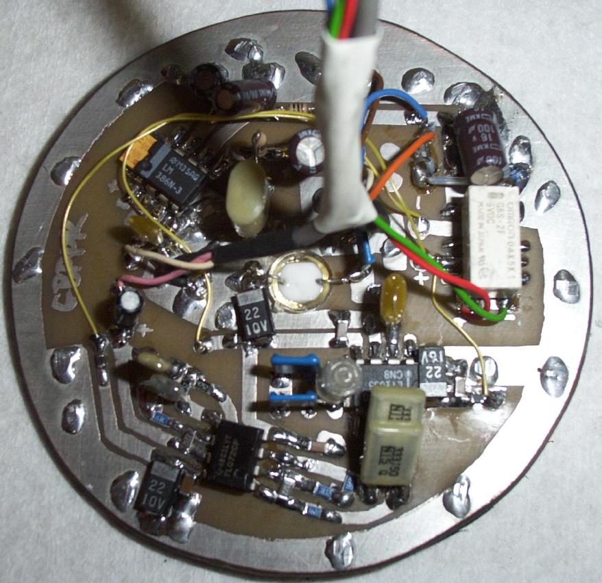
- Here are some preliminary pictures of the GBPPR Laser Bounce Listening Device currently under construction. It will be fully documented when complete. Here is the main PIN-diode receiver circuit board. It is based around a VTP1188S photodiode and a LT1055 op-amp feed into an audio-shaping bandpass filter. It uses a magnifying lens mounted in a PVC tube for the main optical guide path.
- Here are the construction notes for a proper interferometric laser surveillance device (DAVIDSKOLAK).
- Here are the construction notes for a simple dual-beam interferometric laser surveillance device (THOMASTHORNTON).
Notes & Links
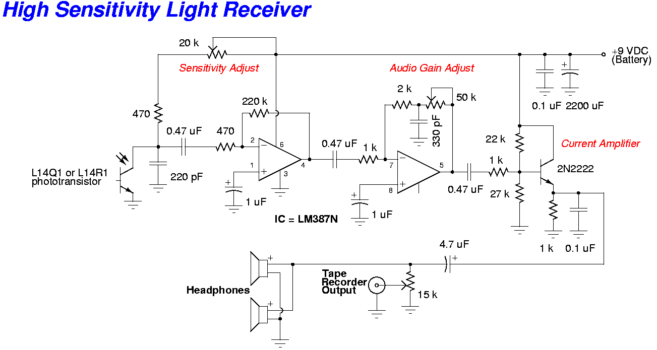
- Alternative Laser Receiver/Amplifier Circuit
- Sam's Laser FAQ
- Signals Defense SD2500/2510 Window Film Security window film capable of attenuating RF and IR signals. (Datasheet)
- System and Methods for Filtering Electromagnetic Visual, and Minimizing Acoustic Transmissions U.S. Patent No. 7,177,075
- System and Methods for Filtering Electromagnetic Visual, and Minimizing Acoustic Transmissions U.S. Patent No. 7,294,368
- System and Method for Filtering Electromagnetic Transmissions U.S. Patent No. 7,405,872
- Method for Temporarily Inactivating a Wireless Communication Device U.S. Patent No. 7,596,850
- Mitigating Laser Microphone Eavesdropping (YouTube)
- Laser Listener by Grand Idea Studios
- An Audio Laser Intercept Demonstration System Straight from the Canadian Diplomatic Technical Security Service. (Mirror)
- Build a Laser Spy Microphone on the Cheap Lifehacker
- "Laser Ear" Laser Listening Device by Global Security Solutions
- GMD2200NEO Laser Microphone This is a "proper" interferometric laser listening system, like which is used by intelligence services. (Datasheet)
- "SNEAK" Laser Listening Device by Espionage Store
- Spectradome Laser Microphone Includes several audio examples.
- Spectradome Professional surveillance and countersurveillance solutions for law enforcement and government.
- SPECTRA Beamer The SPECTRA Beamer C is an active Laser microphone which requires you to plant a disguised Laser transponder on the inside of the target premises, however, in return for your efforts, it will allow you virtually unlimited operating time and an easy, aiming at the target transponder to extract the acoustic information of interest.
- Laser Microphone Basic Version - ARGO-A Model AA79106-B
- Fusions Group ModelFGLD-786 Laser Listening System (Datasheet) (Video Overview)
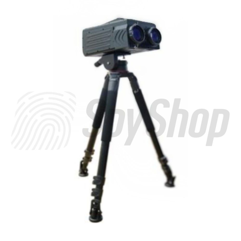
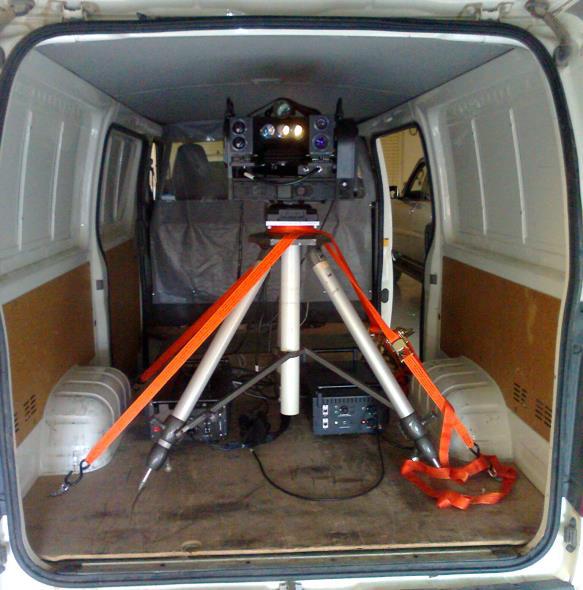
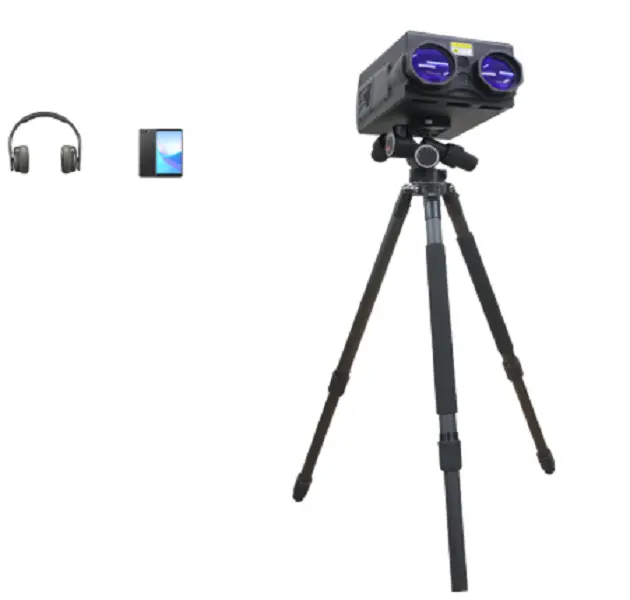
- FUSION's non-reflected beam laser listening device can listen the sounds from Long distance up 5 km line-of-sight from focused window. Our laser listening devices has more function, the image stabilizers for the high immunity against vibrations. It also have special "SIGMA JAPAN" 680-750 nm filters for the cancellation of ambient optical noises. 72 hours maximum listening time continuously through one fully charged battery. The weight of total system including tripod, battery and with packaging is approx. 15 kg. Our laser listening devices are highly robust and mono block. Its mean one do not need to place transmitter and receivers separately. All the system is standalone one unit hand held and can be use on tripod.
- Video (YouTube)
- Endoacustica: LAS-MIC Laser Microphone
- This awesome audio monitoring system works by pointing an invisible laser towards the window glass of the room which have to be monitored. Any vibrations produced by the glass because of interior room sounds, are actually captured by the laser and then transformed into audio informations thanks to a powerful hardware/software demodulator. In order to effectively use the laser microphone audio monitoring system, simply place it at a height in line with the target window and point the laser on the glass. Then the light beam will bounce towards the operator, with an angle of incidence every time different depending on the perceived sound vibrations. LAS-MIC has a wide spectrum of work providing to professionals the highest audio quality and effectiveness. That means that any word, speech, or sound heard in the room will be duly transposed, processed, and transformed into audio information useful for any investigator or police officer.
- Video (YouTube)
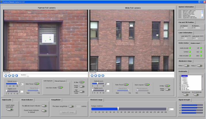
- Discovery Telecom: Multichannel Opto Acoustic Microphone for Audio Monitoring
- Unlike the OAM series, the laser spot is processed immediately by 2 or 4 high-speed cameras, collected into a single picture and cleaned, which allows to achieve the best sound quality. Removes information not from the glass, like other similar devices and with the laser spot with any items - paper, plastic, kitchenware. So that can be used at any angle to the target. Currently there are no analogue on the market: Acoustic surveillance and observation up to 150 m without entering the location of conversation, The spoken word will be picked up from any cooperative material like paper, metal, plastic, textile, etc., Independent form angle of incident, Easy to control: emitter and receiver in a single optical unit. Quick setup and targeting using an integrated, parallax-free camera, Invisible eye-safe laser beam; unparalleled noise performance ratio with low laser power, No interferences from surrounding noises; not influenced by noise between sensor and target, Works even with lowest vibration of surfaces allows monitoring through a glass window into interior spaces, i.e. into cars or rooms.
- OAM-2000 Opto-Acoustical Laser Microphone
- Hewei Defense: Portable Laser Monitoring System
- This monitoring system adopts the new third generation laser listening technology, which effectively overcome the problem of glass window's black hole and realize to observe the target through windows. It can restore the sound signal in fidelity by continuously detecting the small vibration of low voice and impedance target. It is suitable to be used in closed, semi-closed windows environment or open space to effectively listen the person at a long distance.
- Video (YouTube)
- Electromax EMAX-2510 & EMAX-3100 Laser Monitoring Systems
- INT-LM001 Laser Microphone
- Laser Eavesdropping Systems by Insight Technologies (Mirror)
- DNP Long-Range Laser Microphone Only 29,000.00 euros!
- Laser Snooper by Nick Shin (Original)
- PKI Electronic Intelligence PKI2510 Opto-Acoustic Laser Microphone
- The PKI 2510 opens up entirely new perspectives in the field of remote acoustic monitoring. The interferometric technology applied here allows to detect and to make audible even the smallest vibrations, e.g. during conversations, by means of an invisible laser beam almost independently of the detection angle and the material of the target. And it really doesn't matter which target material is used. Whether paper, plastics, metal, etc., the technology can even be used through glass panes into closed rooms or a vehicle without problems. The voice information is transmitted as frequency modulation of the laser beam. For this complex interferometric process, the reflection properties / intensity of the reflected light is absolutely unimportant. The PKI 2510 is quickly assembled and ready-to-operate within a few minutes thanks to the parallax-free electronic target sight. Operating distances of up to 150 m with eye-safe lasers class 1 with greatest possible angle independence offering good speech intelligibility and insensitivity to background noise and interference open up versatile applications.
- PKI Catalog Interception and Monitoring Systems
- Laser Eavesdropping From SpyGame by Scott French and Lee Lapin
- Laser Microphone Overview From Williamson Labs
- Team LuGER: Laser Listener Senior design project, much more up-to-date.
- For the senior design project we will be building a device that will be capable of "listening" to vibrations on a flexible medium by means of a reflected laser signal, such as a window driven by pressure variations due to sound. The device will operate using the same principal as Alexander Graham Bell's "Photophone," in which sunlight reflected off of a Mylar diaphragm to send a voice over a beam of light. The major difference is that we will provide the light source, and thereby be able to control many more factors. Also, this project will incorporate a very scalable modular design that allows for: Analog filtering of incoming laser signal, Digital filtering of incoming laser signal, Analog Storage of processed signal, Digital Storage of processed signal, Analog Playback of real-time or stored data. Using the reflective properties of either a mirror, or a glass window, we hope to reflect a laser from a source, and receive a reflection from the window. By measuring minute variations in the window, we hope to reconstruct the pressure difference (i.e., sound) that caused such tremors on the window, thereby being able to "listen" to what is going on near the window.
- Critical Design Review Presentation (1.6M PDF)
- Original URL
- Covert IR-Laser Remote Listening Device
- This honors thesis details the performance, specifications, and process used in designing and building the Covert IR‐Laser Remote Listening Device (RLD). In the interests of national security and law enforcement, it is some times necessary to perform covert surveillance of a target. The purpose of this product was to create an inexpensive, novel prototype capable of detecting and recording conversation from behind a window or within an automobile. Our final product utilizes window vibrations to deflect an infrared laser beam reflected off of the window surface. The deflections of this reflected beam cause changes in intensity of the light incident upon the photodetector within our product, and these fluctuations are then reconverted to audible sound. The final design prototype has been used to reliably detect sound from behind a window at ranges up to at least 20 feet in the direct reflection condition. This product is the result of funding by Lockheed Martin Advanced Systems in conjunction with the University of Arizona engineering senior design class.
- PDF (4M PDF)
- Sound Retrieval by Demodulating a Reflected Laser Beam From a Vibrating Surface (287k PDF)
- Laser Bounce Listener a.k.a LBR101
- Laser Bounce Listening System
- A Laser Bounce Listening System (LBLS) is a surveillance device that is used for listening private discussions from a far-off distance. It uses a laser beam to detect sound vibrations from a nearby reflecting surface and returns to a receiver that converts the beam to an audio signal. LBLS is designed to allow eavesdropping with a minimal chance of exposure. LBLS can be an effective gadget against terrorism and can be used by intelligence agencies as a spying tool for the places where it is difficult to reach.
- PDF (228k PDF)
- Simple Laser Listener
- The Laser Listener
- Do-It-Yourself Laser Spy Microphone Thread at Schneier on Security.
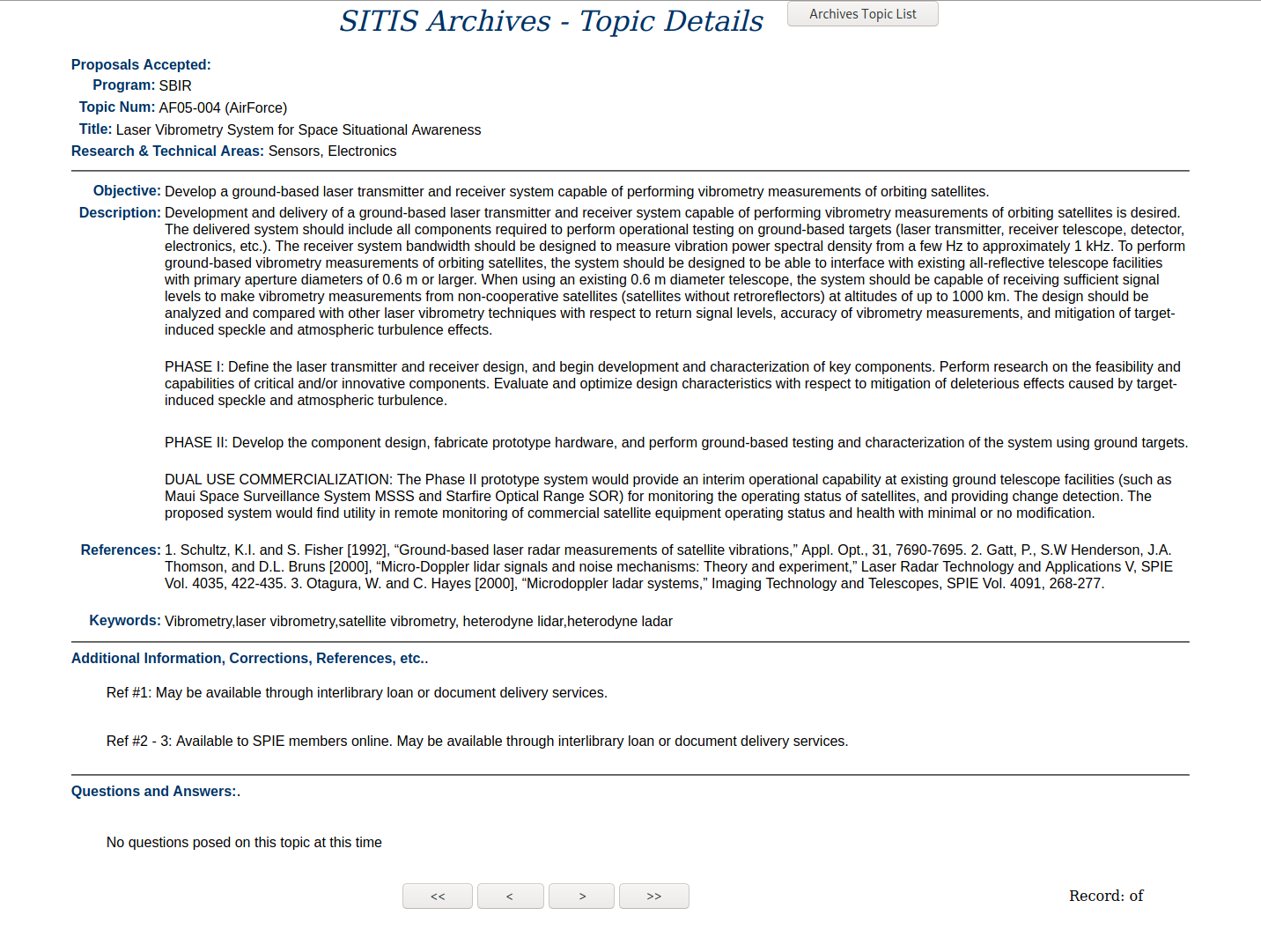
- Laser Vibrometry System for Space Situational Awareness Develop a ground-based laser transmitter and receiver system capable of performing vibrometry measurements of orbiting satellites.
- Ground-Based Laser Radar Measurements of Satellite Vibrations by K. 1.Schultz and S. Fisher (1992)
- Micro-Doppler LIDAR Signals and Noise Mechanisms: Theory and Experiment by Philip Gatt, Sammy W. Henderson, J. Alex Thomson and Dale L. Bruns (2000)
- Imaging Technology and Telescopes Proceedings of SPIE. (ISBN-13: 978-0819437365)
- DIY Laser Long-Distance Listening Device
- Long-Distance Audio Event Detection Using a Laser Doppler Vibrometer
- Integration of Laser Vibrometry with Infrared Video for Multimedia Surveillance Display
- The Laser Microphone by Mark Chounlakone and Julian Alverio
- Laser Surveillance System for Under $20
- The Laser Bounce Window Listener by huvanile
- HOW TO: Make a Laser Espionage Microphone by Kiltak
- The Laser Listener - Espionage Technology for $3
- Bugging the Bedroom by Nicholas Pileggi, Esquire, May 1966 (!)
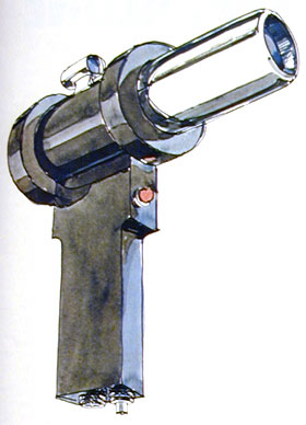
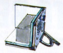
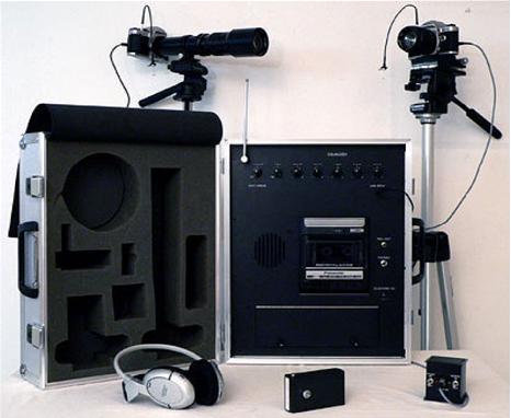
"You're in a room talking to a really trusted friend and no one is within ten miles of you. You lose. The portable laser microphone (left) emits an invisible infrared beam no bigger than a pencil. This beam goes through your glass window and bounces off the mirrored modulator (right), hidden there for the purpose. The beam goes back to the source altered by the sound waves you produce in the room. Miles away a photo amplifier is able to decode your words.
- Optoelectronic Eavesdropping Techniques Practical guide to constructing lightwave transmitters & laser listening systems, by Alan Hoffman
- Laser Microphone Experiment Project 88 from Brad Graham & Kathy McGowan's 101 Spy Gadgets for the Evil Genius (1.8M PDF) (Google Books)
- Laser Window Bounce Listening Device Chapter 13 from Robert E. Iannini's Electronic Gadgets for the Evil Genius (2.5M PDF) (Google Books)
- Laser-Doppler Blood Flowmetry Developments in Cardiovascular Medicine, by A. P. Shepherd
- The Laser Doppler Technique by L. E. Drain
- An Introduction to Optoelectronic Sensors by Giancarlo C Righini, Antonella Tajani, and Antonello Cutolo
- Study of Vibration Measurement by Laser Methods Laser techniques for detecting and measuring vibrations of spacecraft model on shake table.
- The Measurement of Vibrational Power Transmission Using Laser Technology by J. R. Baker, Faculty of Engineering and Applied Science, University of Southampton (8.7M PDF)
- How to Use a Laser to Eavesdrop on Anyone Excerpt from Lee Lapin's How to Get Anything on Anybody. (1.3M PDF) (Google Books)
- Build Long Range Laser Window Bounce Listeners Plans from Information Unlimited.
- Laser Beam Eavesdropping Real-world info from Kevin D. Murray of Murray Associates.
- Big Brother Gains Mobility in Turkey "A Republican People's Party, or CHP, deputy said 11 vehicles with laser eavesdropping systems were the sources for the wiretapping records that were recently broadcast by the media, daily Hurriyet reported yesterday." (Mirror)
- Laser Listening Device (Hack a Day)
- Laser Mic Makes Eavesdropping Remarkably Simple (Hack a Day)
- Black Hat 2009: Powerline and Optical Keysniffing Use a laser to remotely determine keystrokes. (Notes) (Hack a Day)
- Laser Surveillance Defeater Hack a Day (Shomer-Tec Link) (Hack a Day)
- Build the Long-Range Laser Spy System (Hack a Day)
- A Simple Laser Microphone for Classroom Demonstration
- Biasing & Modulating Laser Diodes by John, K3PGP
- Laser Audio Surveillance Device by Vincent Amendolare and Wade Sarraf (2M PDF)
- Photodiode Amplifier Design for Optical Vibrometry by Joe Mariglio
- Ultransensitive Laser Measurements Without Tears Six easily-constructed easily-constructed circuits that can improve the SNR of bright-field laser measurements by as much as 70 dB at low frequency and 40 dB out to 10 MHz, by Phil Hobbs (2.1M PDF)
- Listening to Neighbors: Lasers and Windows 1998 USENET thread.
- Hiding an Ear in Plain Sight On the Practicality and Implications of Acoustic Eavesdropping with Telecom Fiber Optic Cables (PDF, Video)
- Simultaneous Remote Extraction of Multiple Speech Sources and Heart Beats from Secondary Speckles Pattern 2009 (PDF)
- Wide-Angle Laser Audio Eavesdropping Device by Cody Brenneman & Kevin Manelski (2M PDF)
- Torrey Pines Logic LightSpeed G10 High-end optical communication system.
- Torrey Pines Logic LightSpeed B10 Optical voice and data communications.
- MetroLaser Inc. VibroMet Long-Range Laser Doppler Vibrometer
- Vibrometry Basics: Principles of Laser Doppler Vibrometry From Polytec
- Polytec OFV-3001 Laser Doppler Vibrometer Manual (2.1M PDF)
- Laser Doppler Vibrometer Repair of a Polytec laser Doppler vibrometer by W5CDT (YouTube)
- Ometron Scanning Laser Doppler Vibrometer - Type 8330 (300k PDF)
- Ometron VH300+ 8329 Laser Doppler Vibrometer
- Remote Audio Signals Detection Using a Partial-Fiber Laser Doppler Vibrometer
- Self-Mixing Laser Diode Vibrometer (467k PDF)
- Vibrometer Based on a Self-Mixing Effect Interferometer Using a HF6738MG laser diode. (2.5M PDF)
- Variable Configuration Fiber Optic Laser Doppler Vibrometer System (1.3M PDF)
- Speaker Diarisation of Vibroacoustic Intelligence from Drone Mounted Laser Doppler Vibrometers (1.0M PDF)
- Long Range Standoff Speaker Identification Using Laser Doppler Vibrometer (3.0M PDF)
- Laser Vibrometer by Dr. Walter Luhs (6.8M PDF)
- Design of a Low-Cost Laser Vibrometer System Bachelor of Engineering Electronics Thesis by Matiss Malahs (3.1M PDF)
- Targeting the Limits of Laser Doppler Vibrometry (602k PDF)
- Laser Microphone by Bob Junior
- Laser Snooper by Nick Shin
- Product Detector Using LM1496
- Build a Long Range Laser Spy System for Eavesdropping on Your Neighbors
- Noise Reduction Combining Microphones and Laser Listening Devices 2008 (PDF)
- Long Range Audio and Audio-Visual Event Detection Using a Laser Doppler Vibrometer (235k PDF)
- Laser Doppler Velocimeter Using the Self-Mixing Effect of a Semiconductor Laser Diode 1986 (PDF)
- Self-Mixing Laser Diode Velocimetry: Application to Vibration and Velocity Measurement (514k PDF)
- Laser Diode Self-Mixing Technique for Sensing Applications (1.4M PDF)
- Scanning Laser Doppler Techniques for Vibration Testing 2008 (PDF)
- A Laser Device for Remote Vibration Measurement 1967 (PDF)
- Vibration Characteristics of Various Surfaces Using an LDV for Long-Range Voice Acquisition (1M PDF)
- Remote Audio/Video Acquisition for Human Signature Detection (1.4M PDF)
- A New Kind of Laser Microphone Using High Sensitivity Pulsed Laser Vibrometer (PDF)
- A New Kind of Laser Microphone for Photoacoustic Applications (177k PDF)
- The Laser Experimenter's Handbook A learn-by-building course in laser and maser technology, by Frank G. McAleese. (12.3M PDF)
- Semiconductor Diode Lasers by Ralph Campbell and Forrest Mims (3.9M PDF)
- German World War 2 Lichtsprechgerät 80/80 Li Spr 80. 2-way audio communication equipment uses infrared light.
- German Optical Communications This article was taken from the Electronics and Wireless World magazine, August 1985 issue.
- Laser Vibrometry System for Space Situational Awareness (Mirror)
- A Laser Microphone Utilizing the sensitivity of a Michelson interferometer to detect vibrations. (6.4M PDF)
- Laser Microphone Surveillance by Sergey D. Koloydenko (1.1M PDF)
- Modal Response-Based Technical Countersurveillance Measure Against Laser Microphones (4.8M PDF)
- Static Misalignment Effects in a Self-Tracking Laser Vibrometry System for Rotating Bladed Disks (4.1M PDF)
- Remote Laser Interferometry Microphone (PDF)
- Optical Methods for Reproducing Sounds from Old Phonograph Records (2.3M PDF)
- Laser Listening: Could You Eavesdrop on the Guardian?
- Calling Bullshit on the Government's Claim That Spies Could Target the Guardian with Lasers It's not impossible, but scientifically speaking, it'd be very difficult.
- Hackers Can Shine Lasers at Your Alexa Device and Do Bad, Bad Things to It
- How Hackers use an Ordinary Light Bulb to Spy on Conversations 80 Feet Away
- The Visual Microphone: Passive Recovery of Sound from Video (Additional Info)
- Remote Eavesdropping at 200 Meters Distance Based on Laser Feedback Interferometry with Single-Photon Sensitivity (4.1M PDF)
- Laser Meager Listener: A Scientific Exploration of Laser-based Speech Eavesdropping in Commercial User Space (670k PDF) (Data Files)
- Acoustic Eavesdropping Attack Using Self-Mixing Laser Interferometer (6M PDF)
- Multi-Beam Laser Doppler Vibrometer for Landmine Detection 2006 (PDF)
- Lamphone: A New Kind of "Visual Eavesdropping" A lightbulb is all the specialist equipment Lamphone needed to eavesdrop on a conversation in a soundproofed room.
- The Use of the Laser Doppler Velocimeter for Flow Measurements by W. H. Stevenson, Purdue University
- Israeli 'Eavesdropper' Hears You 1,000 Feet Away The Opto-Phone detects long-distance sound vibrations, turns them into words.
- Beating the Laser Bug Electronics Today, March 1973
- Experimental Study of the Propagation of Acoustic Waves by Means of a Laser Doppler Vibrometer (3.8M PDF)
- Laser-Doppler Based Acoustic-to-Seismic Detection of Buried Mines
- Surreptitious Interception of Conversations with Lasers by Forrest M. Mims, III (5.3M PDF)
- Watch How a Hacker's Infrared Laser Can Spy on Your Laptop's Keystroke Hacker Samy Kamkar is debuting his own open source version of a laser microphone - a spy tool that can invisibly pick up the sounds inside your home through a window, and even the text you're typing.
- NSA Spying on Israel: This is How You Treat Your Enemies "The Israelis estimated that the apartment was fitted with highly advanced electronic equipment to eavesdrop on the defense minister's conversations, including a 'laser microphone.' This device shoots a laser beam towards an object in the room the person being spied on is in, normally a smooth surface like a framed picture or a window, and when the beam 'bounces' back, it's affected by the sound vibrations caused to the object from the voice of that person. The device can catch the beam and 'understand' in what way it was affected by the sound vibrations."
- Laser-Based Covert Channel Attack Using Inaudible Acoustic Leakage from Multilayer Ceramic Capacitors "Acoustic noise from computer hardware can cause critical security problems. For example, Genkin et al. successfully recovered the RSA secret key by measuring such acoustic noise with a microphone."
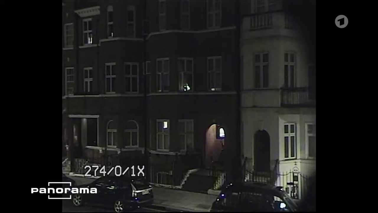
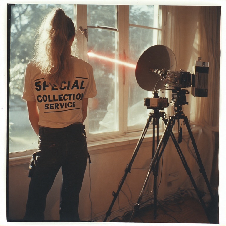
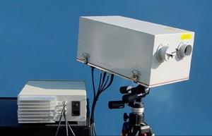
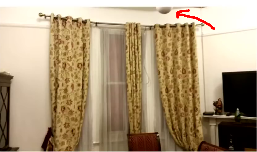
Alleged surveillance of Julian Assange while he was in the Ecuadorian embassy in London with a microwave or laser bounce listening device from a nearby hotel.
They apparently tried to install retroreflective stickers on the embassy's windows in order to get a better reflection for the laser.
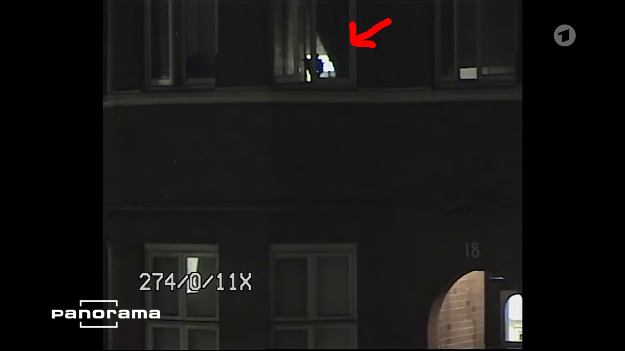
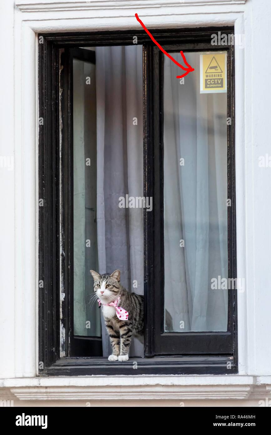
"In January 2018, Witness #2 said [David] Morales urged them to 'place certain stickers on all the external windows of the embassy. Specifically, he requested that I place them in the top left corner of all the windows. The stickers were rather rigid. They indicated that CCTV was in operation.'
'I found this strange because there had been a closed-circuit system for several years, and it didn't make sense to now have to advertise this on the windows of the embassy. Nonetheless, during my visit to London I placed the stickers that had been supplied in the upper left-hand corner of the windows of the embassy.'
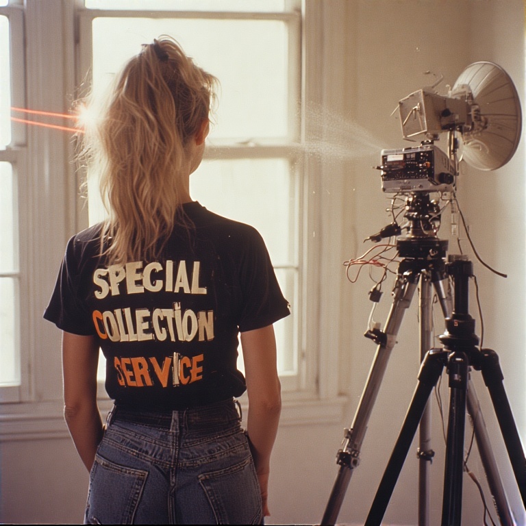
'Our American friends,' Morales said, had laser microphones that were directional and pointed at the windows. They would 'capture all conversations.' But according to Witness #2, since Assange used a white noise machine that 'produced a vibration in the window that stopped the sound being extracted via the laser microphone, which U.S. intelligence had installed outside.'
With the stickers placed in the upper left-hand side of each of the windows, they eliminated the vibration allowing the laser microphones to 'extract conversations.' Witness #2 was upset Morales had not informed them of the real reason for the stickers."
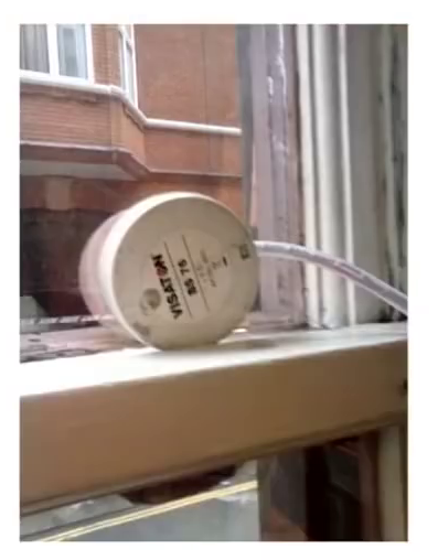


The "stickers" sound like some type of passive retroreflector for a laser-based surveillance device. They could also contain active electronics (note the thick part along the top, it would be powered by a separate high-power laser) for noise cancellation. Someone needs to check if they are still on the embassy's windows and "borrow" one...
Since a noise masking device is usually located near windows, the a potential way to defeat them goes like this:
- Use a Laser Bounce Listening Device to obtain the modulations from the noise-masked window closest to the target. We'll call this SIGNAL A.
- Use a very narrow microwave beam to illuminate the target, then recover the audio information via phase shifts caused by microvibrations. Range gate to eliminate false targets. We'll call this SIGNAL B.
- Using fancy, top secret audio processing tools, subtract the noise modulation SIGNAL A from target audio modulation SIGNAL B.
- Plant a standard RF bug to act as a diversion. Correlate the gathered information via both systems to determine the truth.
- Additional Information
Related Patents
- Optical Vibration Imager U.S. Patent 7,193,720
- Laser Vibrometer U.S. Patent 5,495,767
- Laser Hydrophone and Virtual Array of Laser Hydrophones U.S. Patent 5,504,719 (1.5M PDF)
- Apparatus and Method for the Remote Detection of Vibrations of Diffuse Surfaces U.S. Patent 3,952,583 (226k PDF)
- Laser Interferometry Detection Method/Apparatus for Buried Structure U.S. Patent 4,172,382 (600k PDF)
- Optical Device for Measuring Surface Roughness U.S. Patent 3,804,521 (637k PDF)
- Optical Microphone with Vibrating Optical Element U.S. Patent 5,262,884 (594k PDF)
- Laser Listening Device Detector U.S. Patent 6,114,684 (110k PDF)
- Voice Monitoring System Using Laser Beam U.S. Patent 6,317,237 (273k PDF)
- Heterodyned Self-Mixing Laser Diode Vibrometer U.S. Patent 5,838,439 (1.1M PDF)
- Laser Microphone Wikipedia
- Laser Doppler Vibrometer Wikipedia
Related Audio & Video:
- DEFCON 32 - Optical Espionage: Using Lasers to Hear Keystrokes Through Glass Windows (GitHub, Slides)
- Spying with a Laser (YouTube)
- I Built a CIA Spy Device (Laser Mic) by SomethingAboutScience
- Laser Diode Self-Mixing: Range-Finding and Sub-Micron Vibration Measurement (YouTube)
- Lasermikrofon - Interferometer Laser listener made using a Michelson interferometer. (YouTube)
- CIA Laser Listener Video describing the CIA's version of this device which uses a prism for the return beam. You can get a similar result using certain brands of hair spray (Aqua Net) or similar spray-on reflective coatings on the target window. (YouTube)
- Spying with a Laser by Household Hacker (YouTube)
- How to Make a Laser Microphone by Victor Minces (YouTube)
- myLaserListener - Laser Microphone by Oli Pont (YouTube)
- Fun With Lasers and Audio (and Synths) by Benn Jordan (YouTube)
- The Laser Eavesdropper - Christmas Lectures with RV Jones RV Jones demonstrates the hottest spy gadget in espionage stories at the time - a laser eavesdropper. From 1981! (YouTube) (Full Lecture)
- Laser Microphone for Audio Surveillance via Window Panes by Applied Science (YouTube)
- I bounced a laser beam off of a window in my house and recovered the audio from inside the room via the beam deflection. I used a Hamamatsu S7815 amplified photodiode and connected it with a 9V battery to my stereo's microphone input jack. The audio quality was very low -- probably due to the double-pane windows in my house. Speech was just barely intelligible. I also tested the procedure of bouncing a laser beam off of a framed picture that is hanging on the wall inside the room to be monitored. The reflected beam will hit a wall somewhere else in the room, and the dot can be monitored by a telescope from remote. The goal would be to measure the beam wobble via the telescope and recover the audio without needing a stringent geometric relation to the target room. This didn't work at all, but I think with a sensitive detector, it has potential.
- Comment from Brian Park: "What you need to do is recover the PHASE modulation of the beam; not spacial modulation. You use a setup similar to what you show with the telescope, but you split off some of the light from the laser and pass it through an acusto-optical modulator and shift it 455 kHz up or down. The return beam is mixed with this frequency-offset light and detected with the photodiode. This is fed into the 2nd IF stage of a FM receiver. For best results, you have 2 beams; one shining on a solid surface in the target, and the other on the moving surface, and difference those. Otherwise, you will hear toilets flushing, road traffic, etc. The laser must have a coherence length equal to 2x the total distance to the target. You usually insert an etalon into the laser cavity to accomplish this. I worked on such systems!"
- Comment from Brian Park: "This is more about getting highly specialized optical components than 'building circuit according to schematic.' First, you will need a laser with a coherence length twice the distance to the target. This is not a simple thing (most lasers are not good enough). Even measuring it is challenging, as you need a stable platform that is as long as the range you plan to work. The acoustic-optic modulator is insanely expensive. They are best gotten from old laser printers (before laser diodes were invented). Regarding the amplitude method that Applied Science uses, he provides all the schematics you need (for biasing the photodiode). You need extreme shielding. Mount it in a small grounded metal box with a small hole for the light to enter. Connect that capacitive coupled to low-level microphone input of audio preamp."
- Comment from Brian Park: "[In regards to putting a retro-reflector on the target window] If you do that, you get the motion of the WINDOW, which includes wind, car horns, etc. You should target something IN the room, such as a piece of paper lying on a desk."
- Comment from Brian Park: "No need to enter room. Target something already IN the room that is thin, light & will respond to audio much better than heavy window glass. Yes, reflection is diffuse, but you counter that by focusing a telescope on the target spot. The telescope both focuses the outgoing light to the target & the return light. Use a polarizing beamsplitter to separate the return light (the diffuse reflection scrambles the polarization of the return light). You can scan room objects while listening to find the best spot to illuminate."
- Comment from Brian Park: "Lock-in amplifiers don't cut it in this case. The only thing you can lock on is the amplitude; the phase is lost as soon as you go through the first slotted spinning wheel/and (square-law) photodiode detector. Lock-in is useful for amplitude unformation when you can reduce post-detection bandwidth to a small fraction of a Hz. What is 'locked on' (in coherent scheme) is the oscillations of the source light itself. The coherent scheme does not introduce the 'noise-enhancing' effect of the multiply in the square-law detector. It can be shown that the noise bandwidth of a receiver is the geometric mean of the bandwidth at the square-law detector (which is terahertz) and the post-detection bandwidth. Even with only 2 kHz post-detection (to barely pass the audio), the noise bandwidth is in the MHz! Using phase-coherent source, noise bandwidth can be reduced to 10 kHz. Also, the true nature of the motion you want to pick up is translation along the axis of the beam, not rotation (which is what amplitude scheme picks up)."
- Laser Spy Museum exhibit which demonstrates the laser bounce audio surveillance technique. (YouTube)
- Smoke Mic - Prototype One World's first laser-smoke microphone prototype of U.S. Patent 7580533. (YouTube)
- This Laser Can Hear You Talk by The Action Lab
Hewlett-Packard Lasers & Optics
- HP 5501A Laser Head System Operating and Service Manual (HP 05501-90021, Jan. 1980)
- HP 5501B Laser Head Operating and Service Manual (HP 05501-90035, Sept. 1986)
- Agilent Laser and Optics User's Manual - Volume 2 (HP 05517-90086, Sept. 2007)
- HP 5527A Laser Position Transducer & HP 5507A Position Sensing/Control User's Manual
- Hewlett Packard/Agilent Metrology Laser/Interferometer Documentation Page
Other Related GBPPR Projects:
Return to Homebrew Military & Espionage Electronics Page