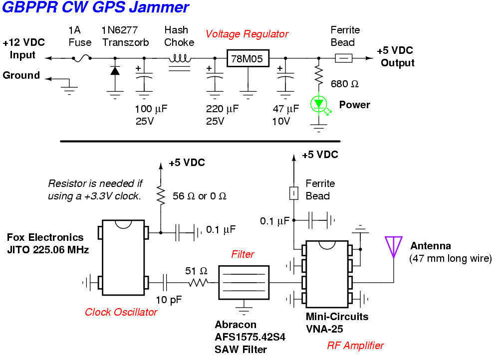
This is a simple jammer for the L1 GPS frequency (1575.42 MHz). It is based around a Fox Electronics JITO custom frequency clock oscillator operating at 225.06 MHz. The oscillator's output is then filtered to isolate the seventh harmonic at 1575.42 MHz via a GPS bandpass SAW filter. This harmonic is further amplified via a Mini-Circuit VNA-25 MMIC RF amplifier, which then feeds a small, surface mount Yageo antenna.
The final product is a fairly limited-range Continous Wave (CW) jammer centered on the GPS L1 receive frequency. The jammer only has an effective range of a few feet (if that) and only jams the lower-cost Standard Positioning Service (SPS) GPS receivers. Fancy GPS receivers can actually "filter out" a CW jammer. Use broadband noise jammers to take out those...
The custom Fox JITO clock oscillator is Mouser part number: JITO-AC3AE-225.060
This is for a 14-pin DIP package and +3.3 VDC operation. The one shown in the following pictures was an older sample which operated at +5 VDC. The oscillator is "set" at the factory, so delivery can take a few weeks.
The GPS bandpass SAW filter is Digi-Key part number: 535-9239-2-ND
This is Abracon part number AFS1575.42S4. This little bastard is only 3 mm x 3 mm. Have fun!
The surface mount GPS antenna was Digi-Key part number: 311-1225-ND
This is the Yageo 4313-114-00158 SMT GPS antenna. They don't seem to carry them anymore (of course!), so use a 47 mm long piece of wire for the antenna instead.
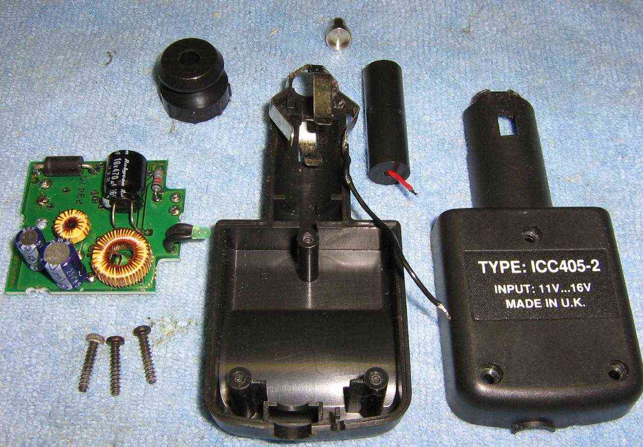
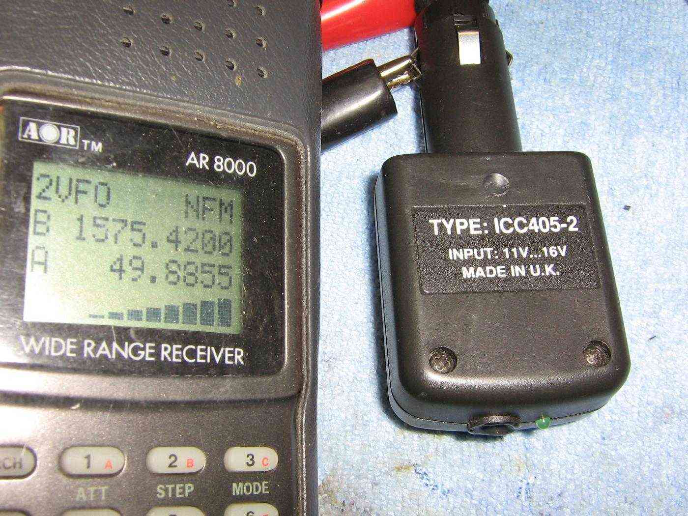
Case overview. It will be mounted inside one of those cellular phone voltage adapters which plug into a vehicle's cigarette lighter. Be sure to save the input filtering network when you take the voltage adapter apart.
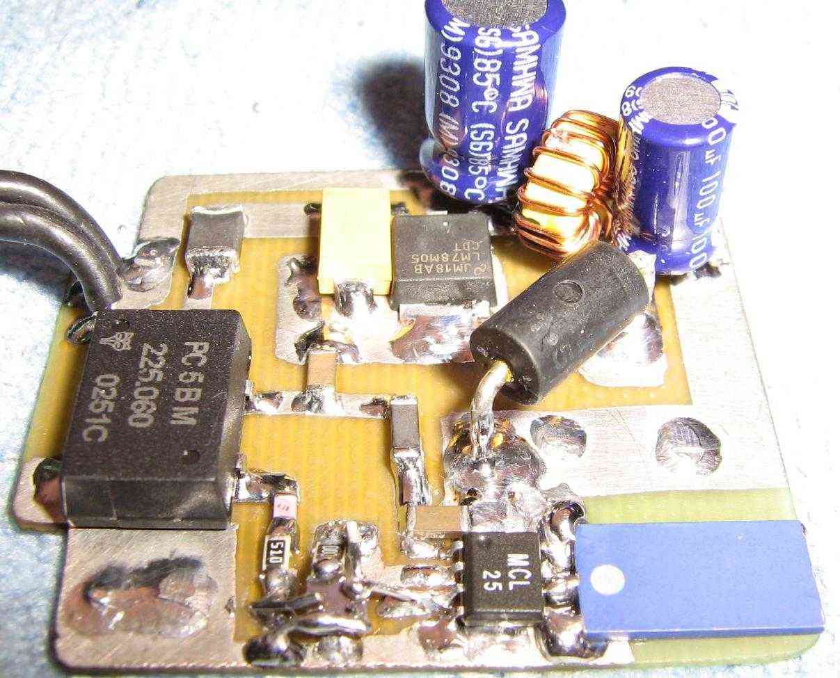
Get all the parts, make up a PC board and solder them like so. Heh.
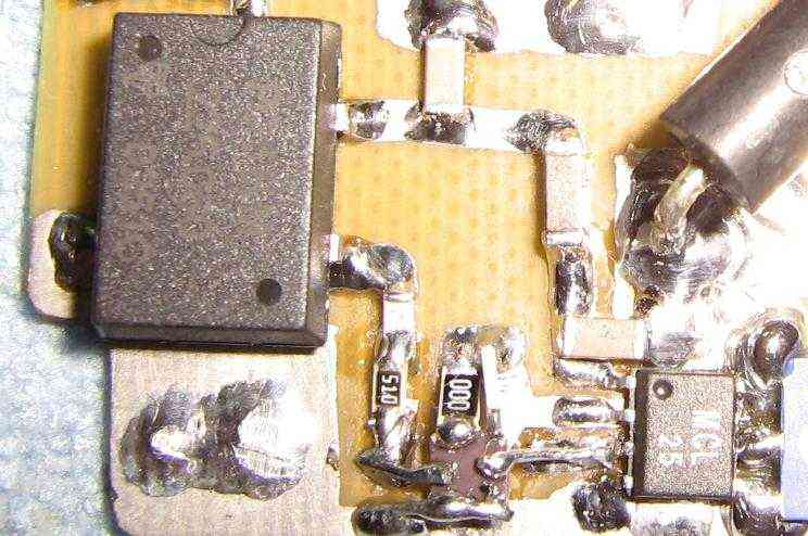
Close up picture of the Abracon AFS1575.42S4 bandpass filter. It's a mess. Place it so the solder pads stick up into the air "dead bug" style, then solder little extension wires (or zero-ohm resistors) from the pads to the traces. The use of zero-ohm resistors was actually easier than using wires. Stand them on end and solder them to the filter's pads. You may want to practice a bit...
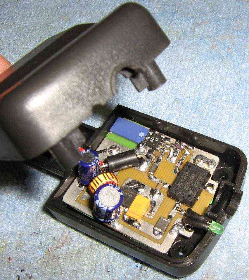
Mount the jammer PC board inside the voltage adapter's case. Secure the board using art foam and hot glue. Be sure the power LED is not pinched.
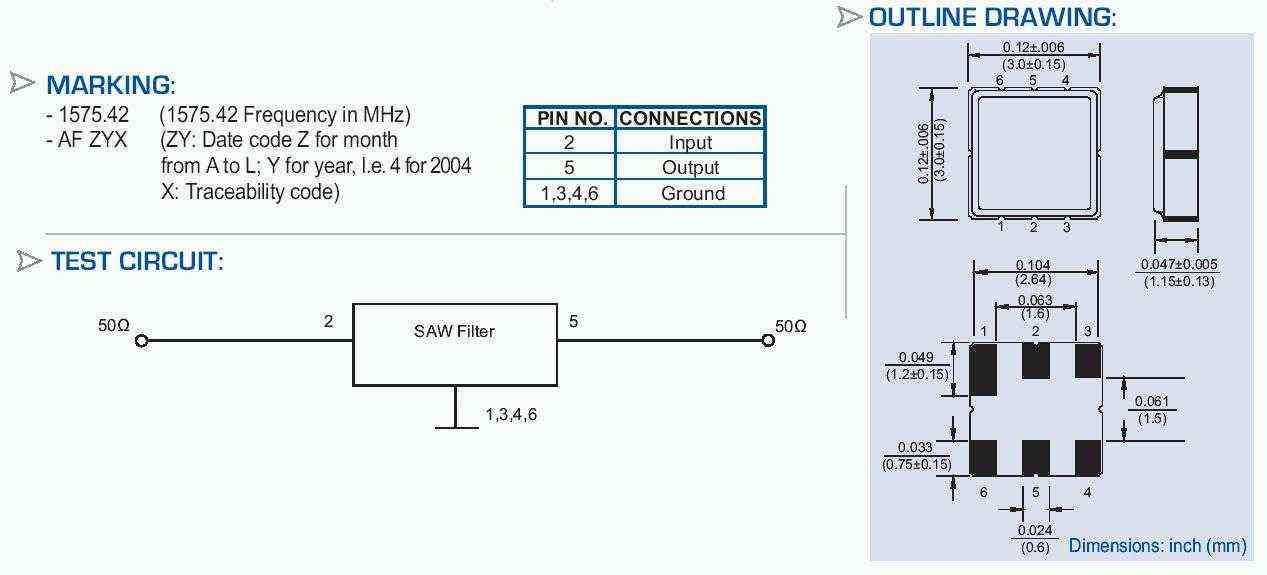
Abracon AFS1575.42S4 SAW filter pin-out. With the solder pads facing up, RF input is pin #2 and RF output is pin #5. The "long" solder pad is pin #1. The other pads need to be grounded.
You know where you are? You're in the jungle, baby. You're gonna die...