
Overview
A High-Energy Radio Frequency (HERF) device is nothing more than an easily controlled source of very powerful microwave radio energy.
Sound like it will be complicated?
No, it's a microwave oven, you dumbass.
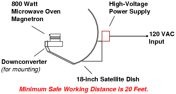
All you need to make one, is to spend some time digging around in your neighbor's trash. You'll need to locate an old microwave oven, which will probably still be working or easily fixed, and one of those new 18-inch satellite dish systems, complete with the low-noise block downconverter. It should be noted that microwave ovens are a source of very dangerous high-voltages which can kill you.
This particular HERF device was built for one purpose. To cause extensive interference in remote audio systems in which their volume is way too loud for my liking.
A small, consumer microwave oven's magnetron puts out around 800 watts (peak) of RF power at a frequency of 2.45 GHz. Some industrial microwave ovens operate at 915 MHz. By placing the magnetron at the focal point of the 18-inch satellite dish, the magnetron's RF output will be increase by around 15 dB. The Effective Radiated Power (ERP) output will be at least 20,000 watts. Good enough to cook stereos 50 feet away. Oh, yes, those big ten foot C-band dishes will get you up to 1,000,000 watts ERP.
This project will include lots of pictures, as they are easier to follow.
Block Diagram
Fundamental Function of the Magnetron
From the book "Microwave Oven Repair," by Homer Davidson
In a microwave oven, the magnetron tube generates the microwaves. They are transmitted to the oven cavity, reflected by the sides of the oven area, and then absorbed within the food that is in the oven cavity.
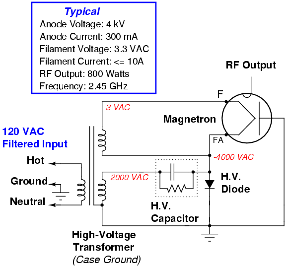
The magnetron's cathode is located in the center of the magnetron and is a filament that boils off electrons when it is hot. The cathode is connected to the negative side of the power supply, which has a potential of approximately 4,000 volts with respect to the anode, which is connected to the positive side. The 4,000 volts potential is produced by mean of the high-voltage transformer and doubler action of the capacitor and diode.
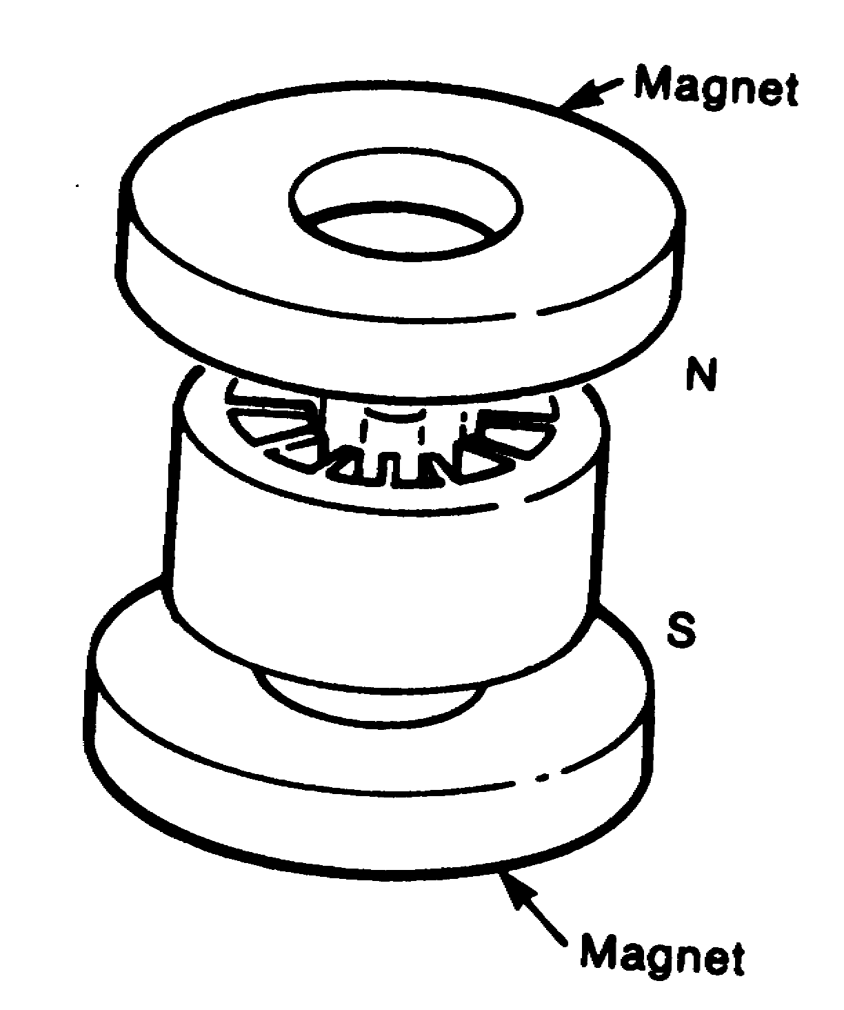
The electrons are negative charges, which means they are strongly repelled by the negative cathode and attracted to the positive anode. The electrons would travel straight from the cathode to the anode if the 4,000 volts potential were the only force acting in the magnetron (Figure 1). However, the magnetron is a type of diode with a magnetic field applied axially in the space between the cathode and anode by means of two permanent magnets (Figure 2).
Figure 1 - The electrons travel from cathode to anode.
Figure 2 - The two permanent magnets are found between cathode and anode.
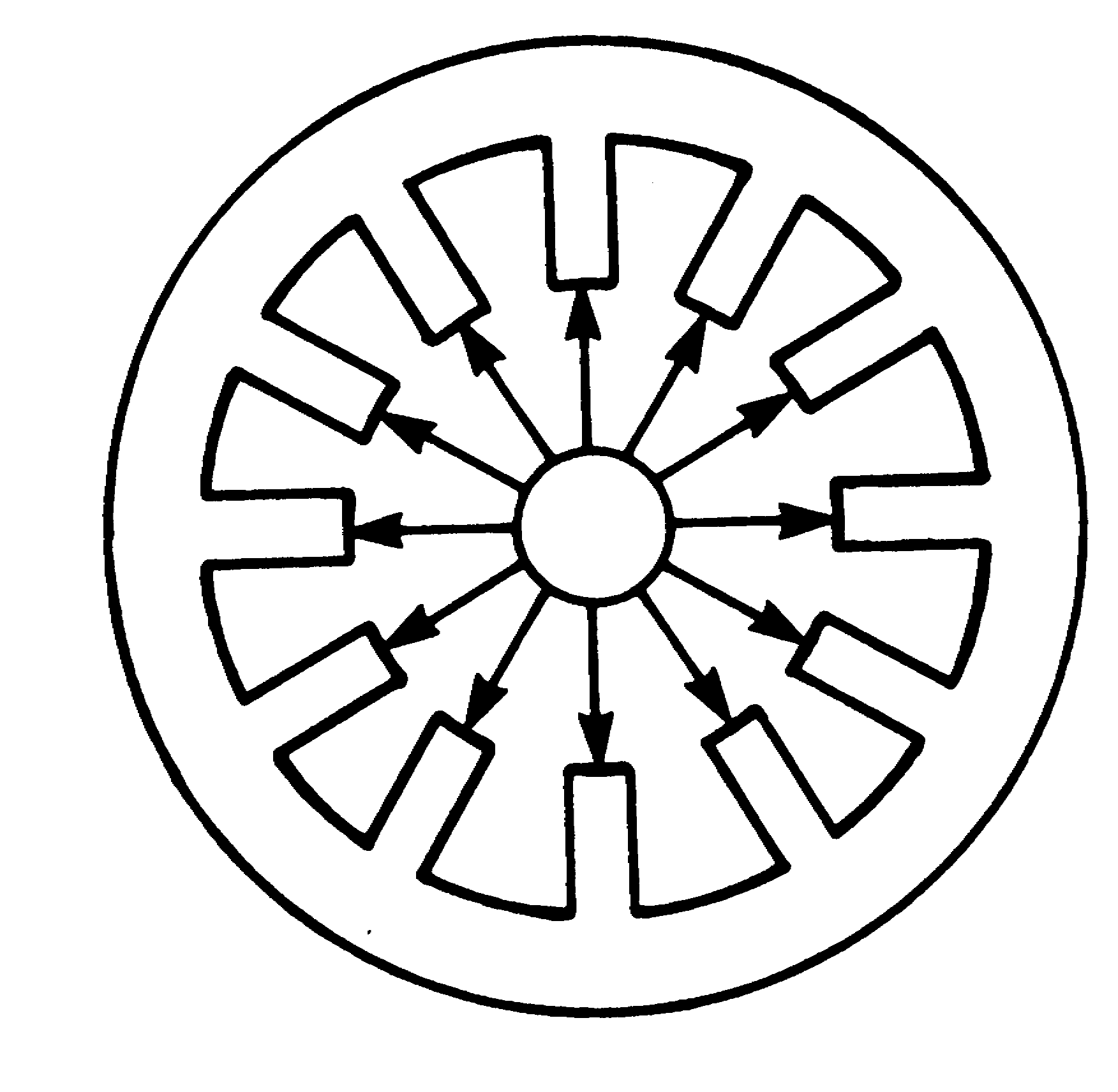
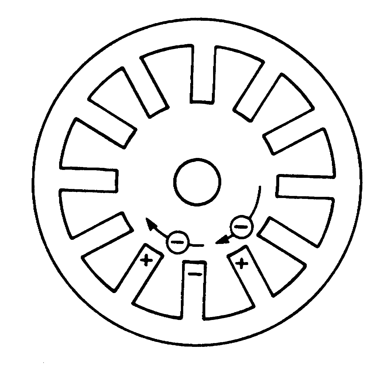
If a magnetic field of sufficient strength is applied between the cathode and the anode, an electron would travel in a path almost at right angles to its previous direction, resulting in a circular motion of travel to the anode (Figure 3). Eventually, it would reach the anode.
Figure 3 - The electrons travel in a circular motion to the anode.
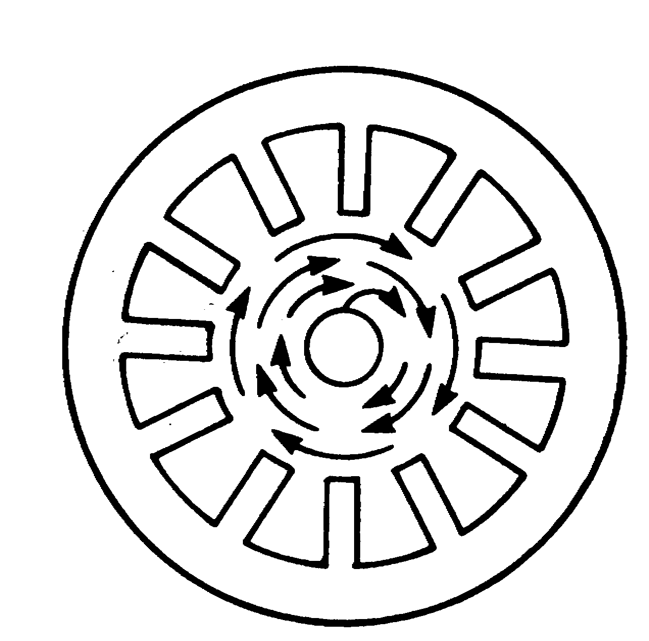
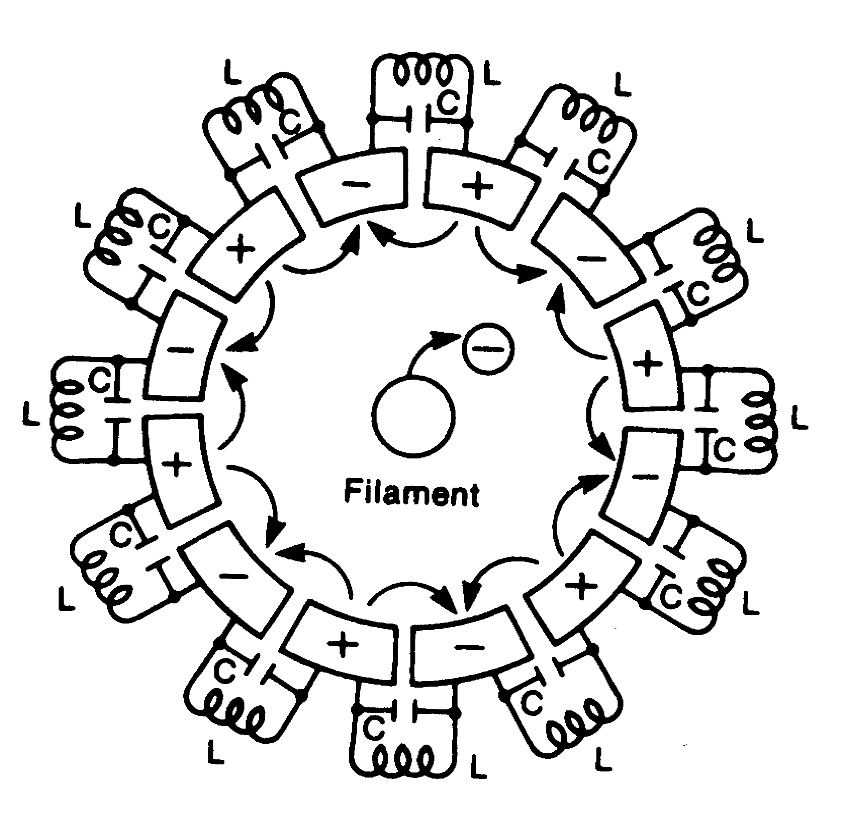
This circular motion by the electrons induces alternating current in the cavities of the anode. When an electron is approaching one of the segments between the two cavities, it induces a positive charge in the segment (Figure 4). As the electron goes past and draws away, the positive charge is reduced, while the electron is inducing a positive charge in the next segment. This inducing of alternate currents in the anode cavities can be thought of as a lumping together of the resonant circuits (Figure 5).
Figure 4 - When the electron approaches one of the segments between two cavities, it induces a positive charge.
Figure 5 - Lumping the resonant circuits.
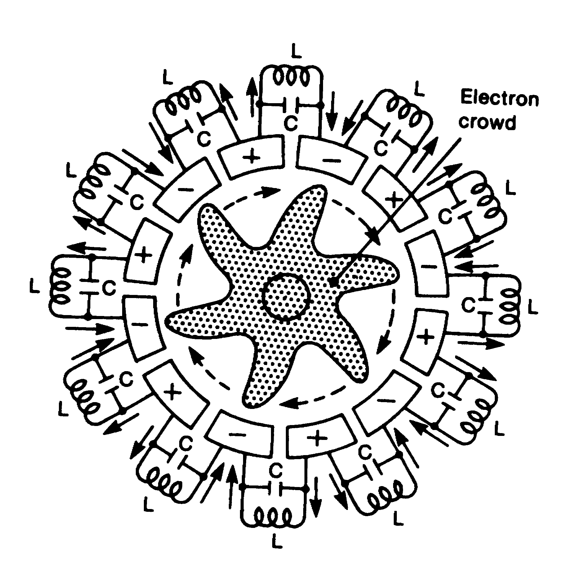
In the actual operation of the magnetron, the electrons crowd together as they go around and, influenced by the forces of high-voltage and the strong magnetic field, form a spoke-wheel pattern (Figure 6). This crowd of electrons, which has much stronger energy than a single electron, revolves around the anode and eventually reaches the cavities, resulting in the continuous oscillation of the resonant circuits. The high-frequency energy, produced in the resonant circuit (cavities), is then taken out by the antenna and fed into the oven cavity through the waveguide (Figure 7).
Figure 6 - The strong magnetic field from a spoked-wheel pattern.
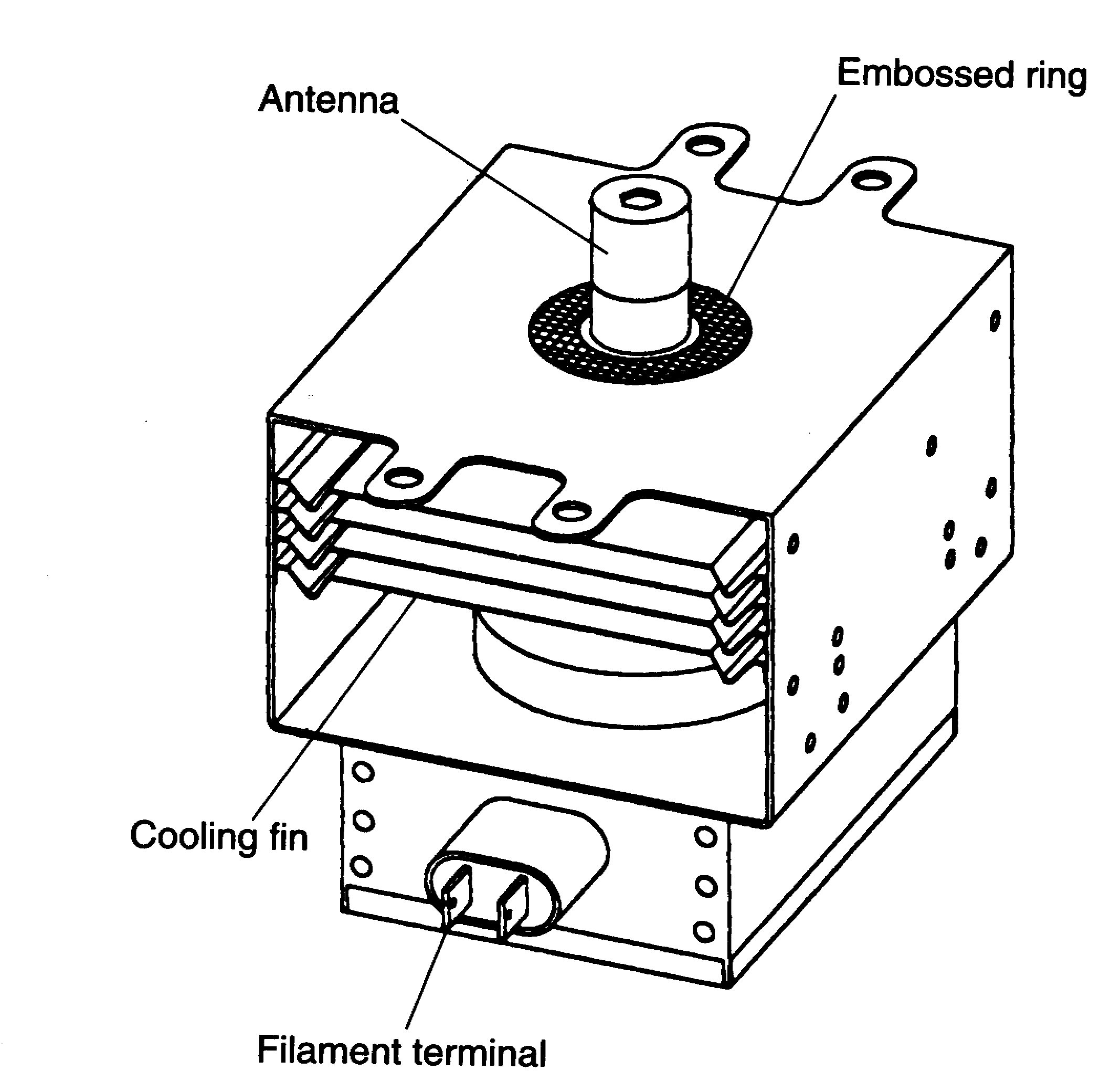
Figure 7 - The magnetron tube found in all microwave ovens.
High-Voltage Circuits
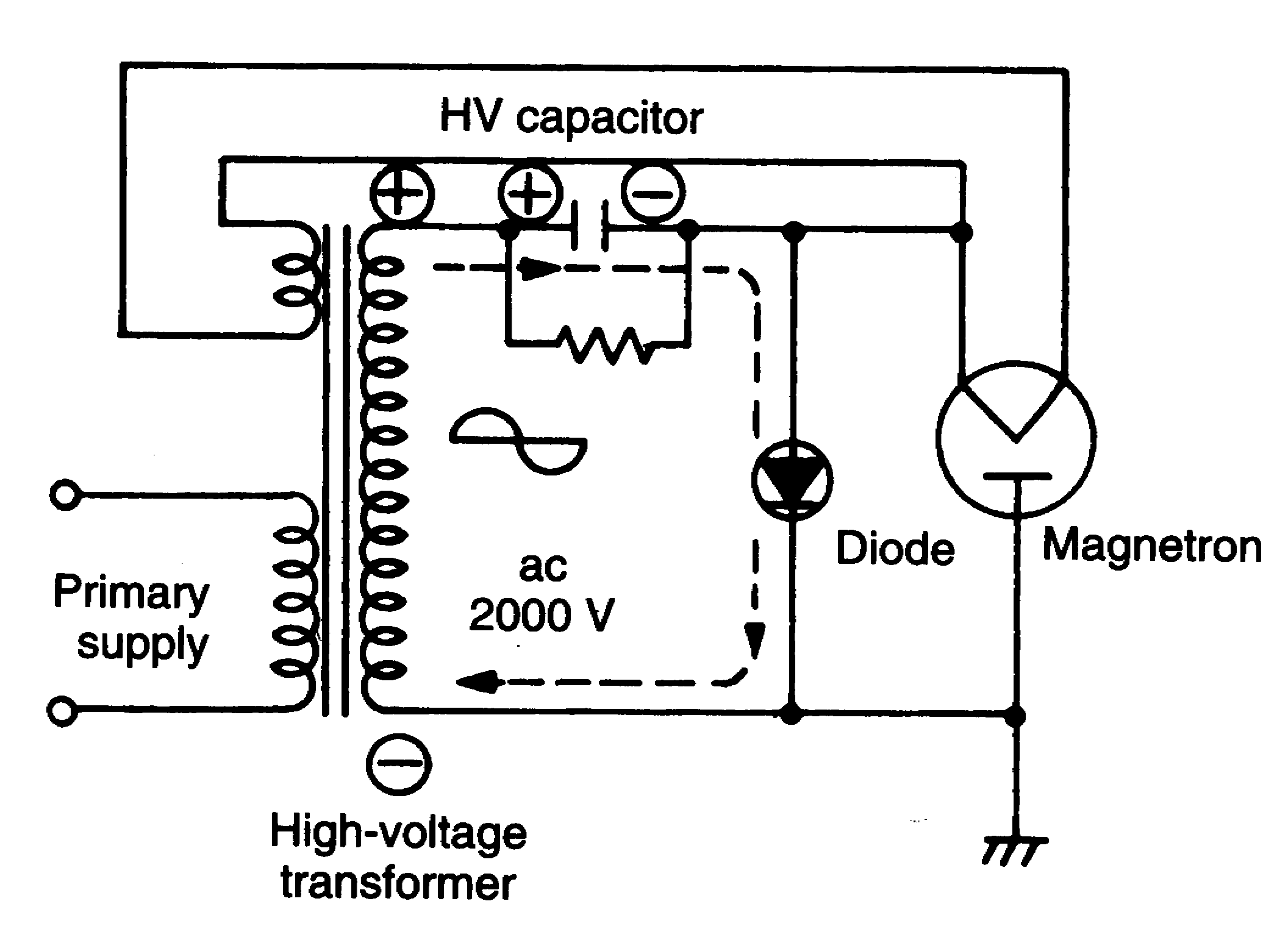
In most of the microwave ovens, the high-voltage is generated by the action of the diode and the charging of the high-voltage capacitor. This circuit is called a half-wave voltage doubler circuit. This circuit is commonly used because it is economical as a smaller transformer and capacitor can be used to produce the high-voltage.
The typical half-wave voltage doubler circuit with the capacitor and diode are connected in the high-voltage transformer secondary (Figure 10). Generated from the filament winding on the high-voltage transformer, 3.3 VAC is applied to the magnetron filament through noise suppression chokes and capacitors. Two chokes and capacitors, enclosed within the magnetron shielded case, prevent microwaves from affecting radios and television sets.
The AC voltage of approximately 2,000 volts or more (depending on the output power of the microwave oven) is generated from the secondary winding of the high-voltage transformer. The capacitor charges through the diode during the first positive cycle of the AC from the transformer (Figure 8). The charge path of the capacitor is shown by the dashed lines. During the capacitor charging time, the magnetron is off because the diode shunts it. The capacitor charges to approximately 2,000 volts or more.
Figure 8 - The capacitor charges through the diode during the first positive cycle.
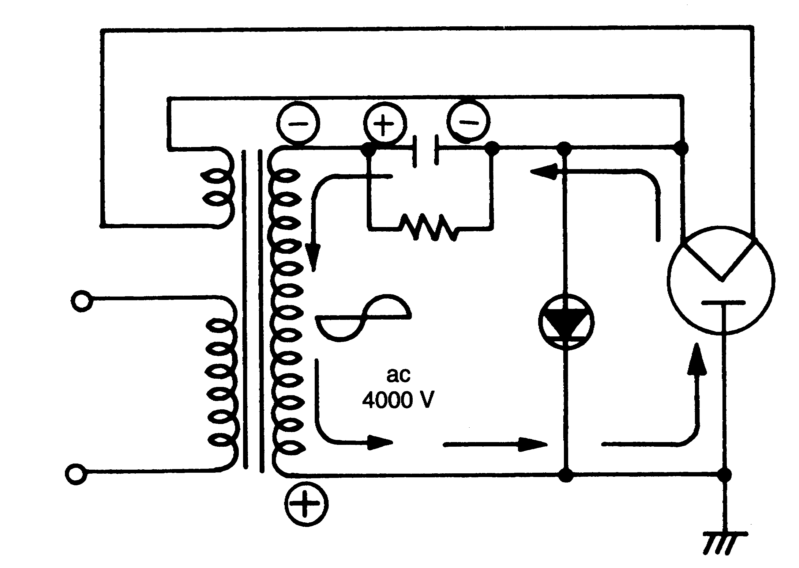
During the negative half-cycle, the voltage on the capacitor and the voltage across the transformer secondary winding are combined and applied across the magnetron's anode, shown by the solid lines (Figure 9). The resultant potential of approximately 4,000 volts is used to oscillate the microwaves from the magnetron. Notice that the magnetron is pulsed on and off at a rate of 60/50 Hz, depending on the line rate used.
Figure 9 - During the negative half-cycle, the voltage on the capacitor and the voltage on the transformer secondary winding are applied across the magnetron.
Figure 10 - The large power supply transformer supplies high-voltage to the voltage doubler circuit and low-voltage to the filament on the magnetron.
Pictures & Construction
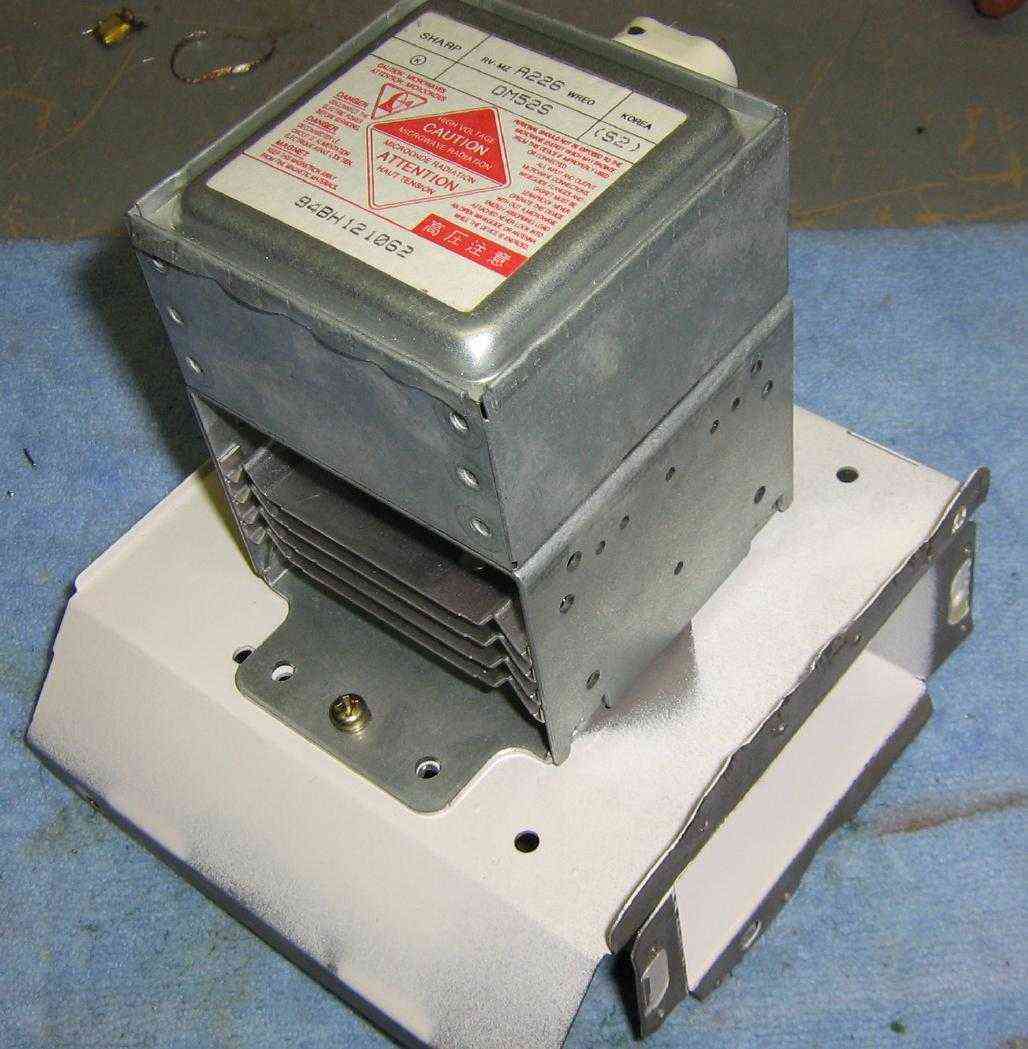
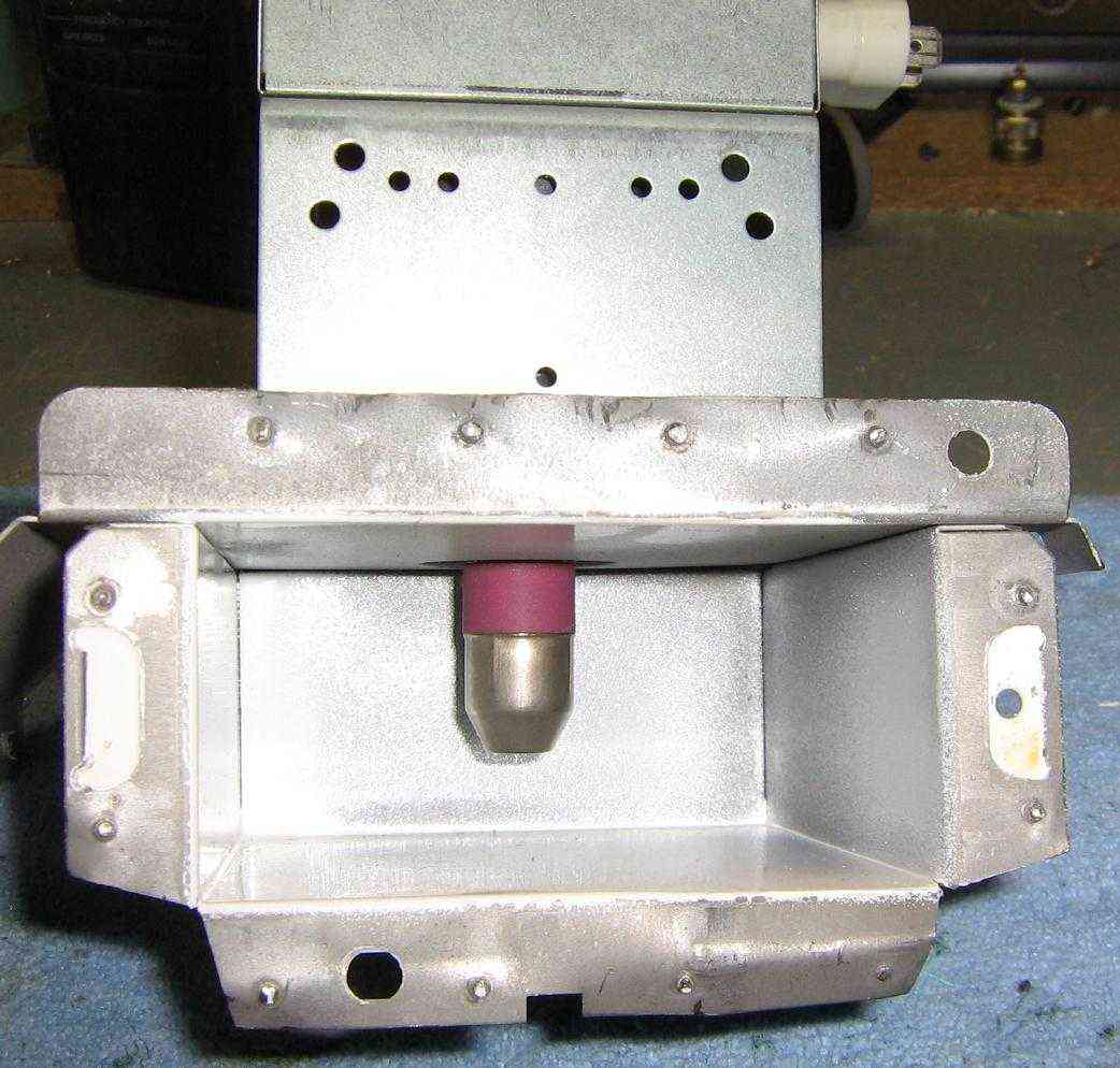
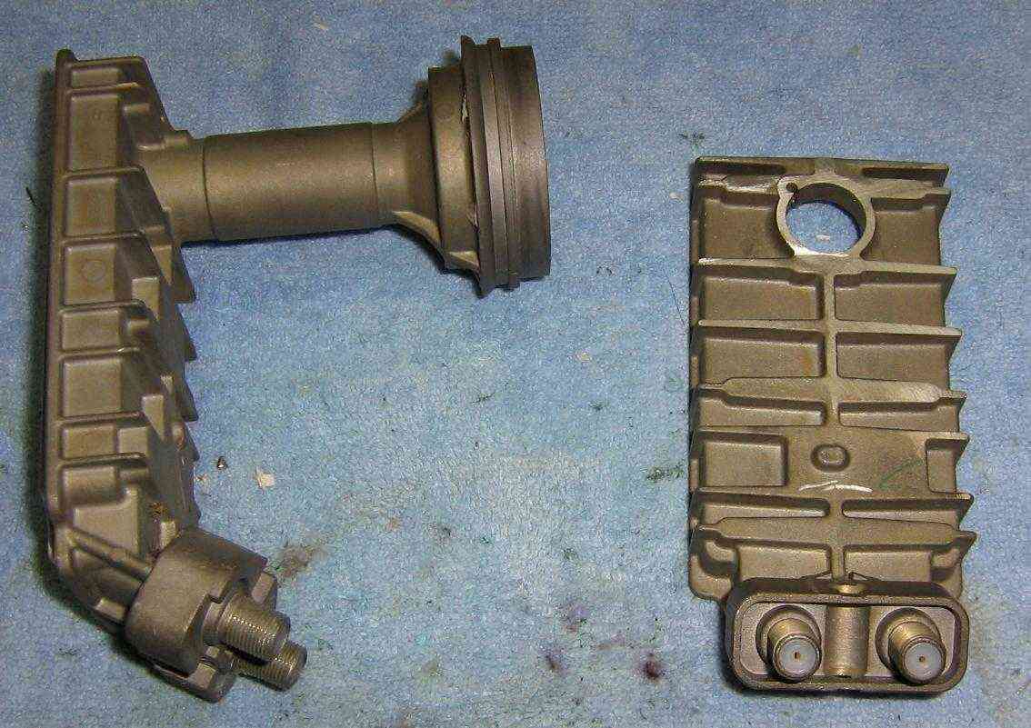
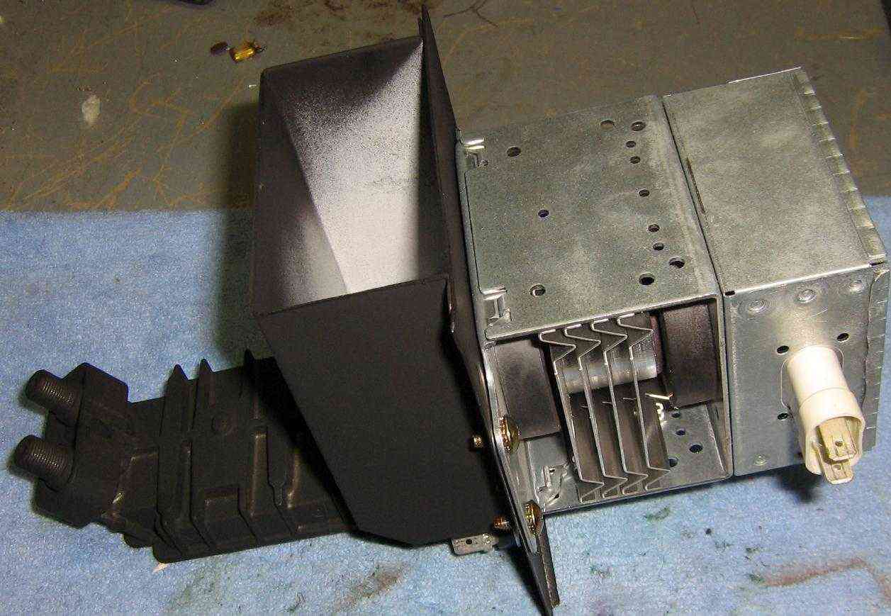
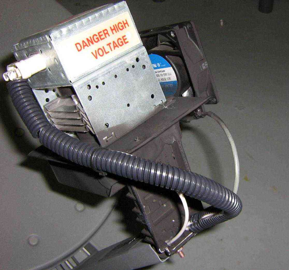
Magnetron tube from an old microwave oven, I don't remember the oven's model number. Be sure to save the little metal waveguide assembly and any mounting hardware.
Waveguide assembly internal view. The final emitted RF output is via the antenna below pink ceramic "cap."
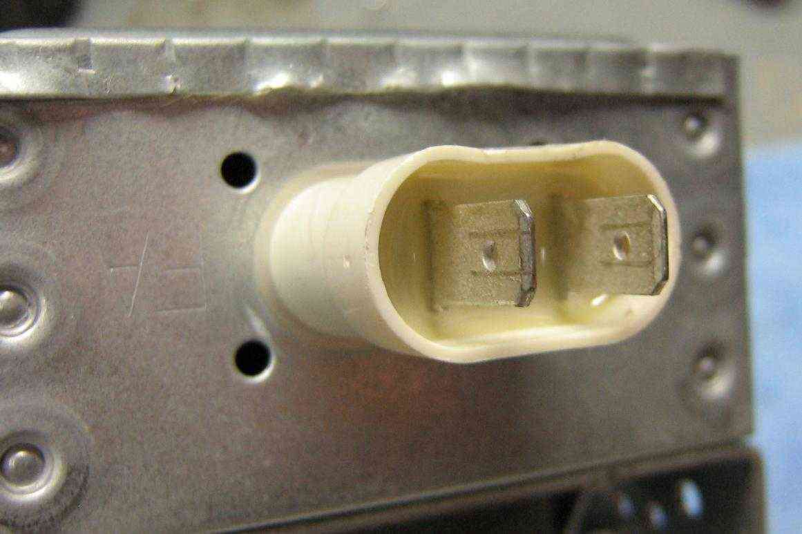
The magnetron's filament (heater) connection, which also serves as the cathode. The anode is grounded. They use standard spade lug connections. The little plastic cover assembly is actually a feed-through capacitor to keep any RF out of the high-voltage lines.
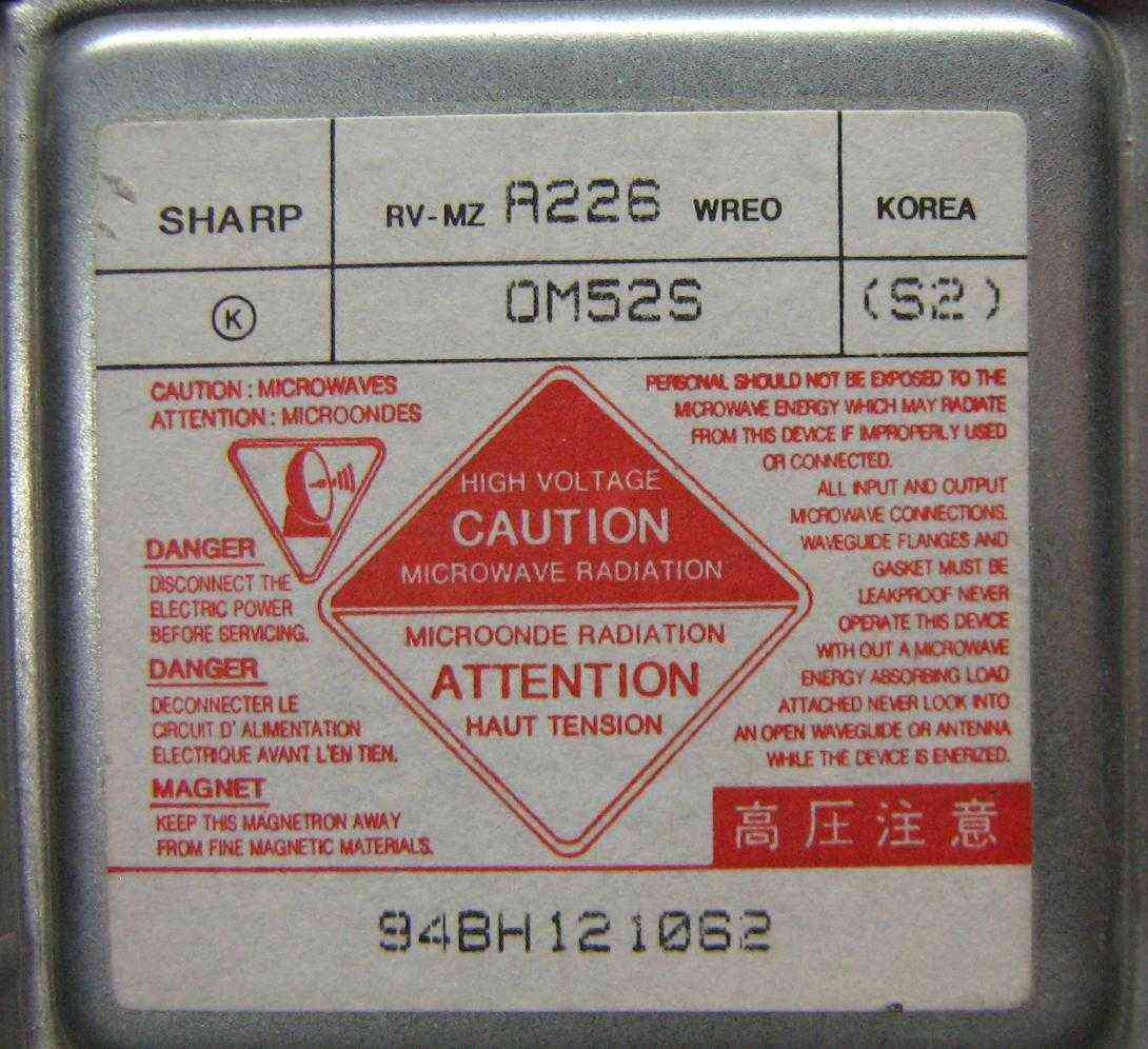
Closeup picture of the magnetron's label. It is a Sharp OM52S. The price runs around $30 on various electrical parts websites and eBay. All consumer model magnetrons will be essentially the same.
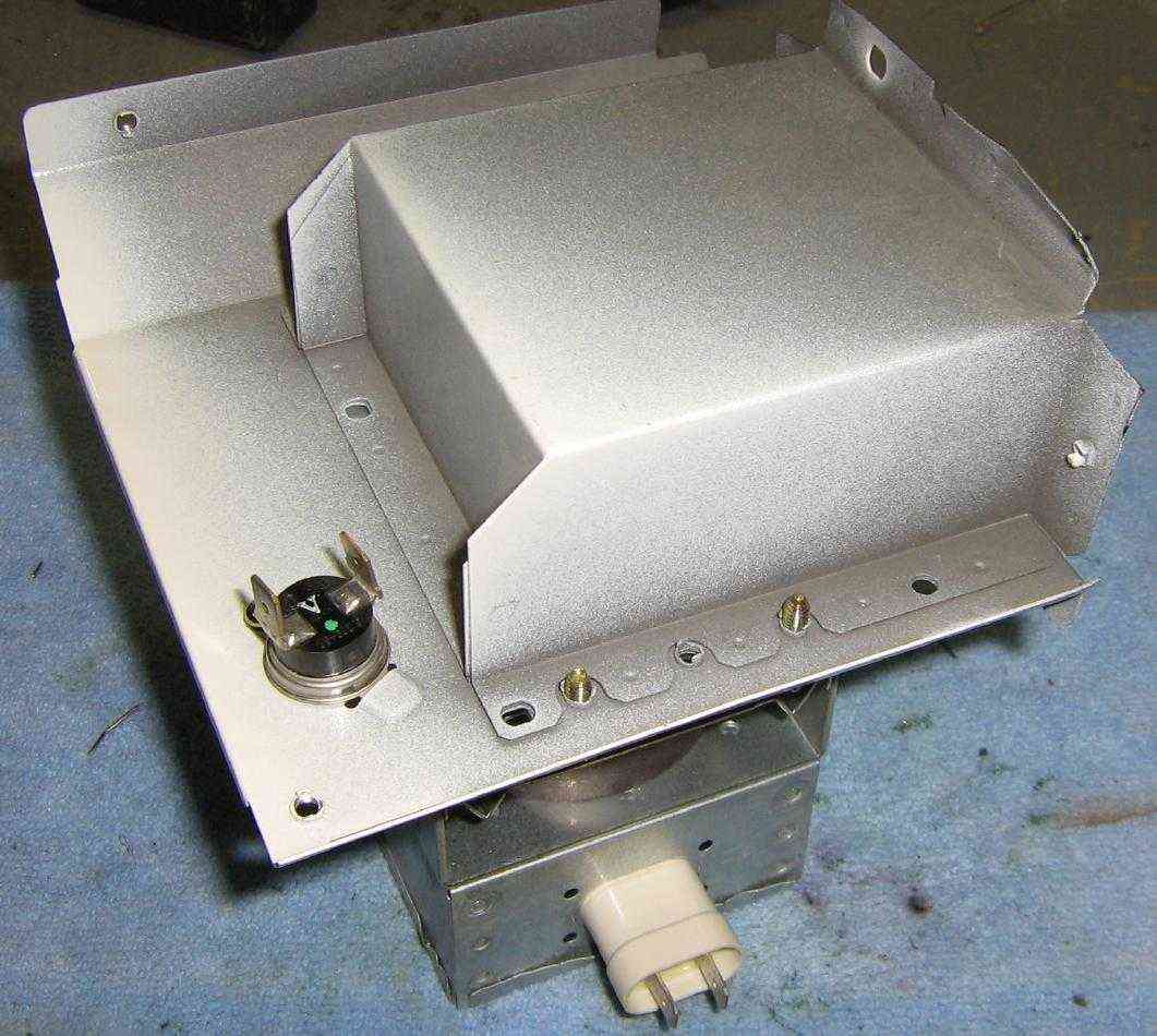
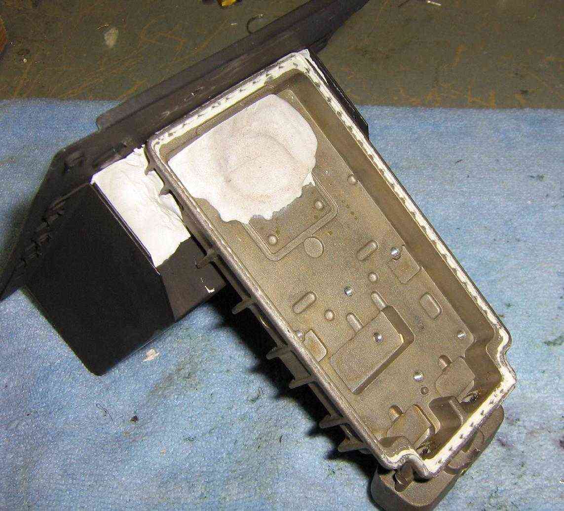
Bottom view of the waveguide assembly. You may wish to utilize the thermal shutdown switch. It will go in series with the incoming "hot" AC power line.
Top view of the waveguide assembly. Note how there is no paint around where the brass embossed ring on the magnetron meets the waveguide. This is to prevent any dangerous RF leakage.
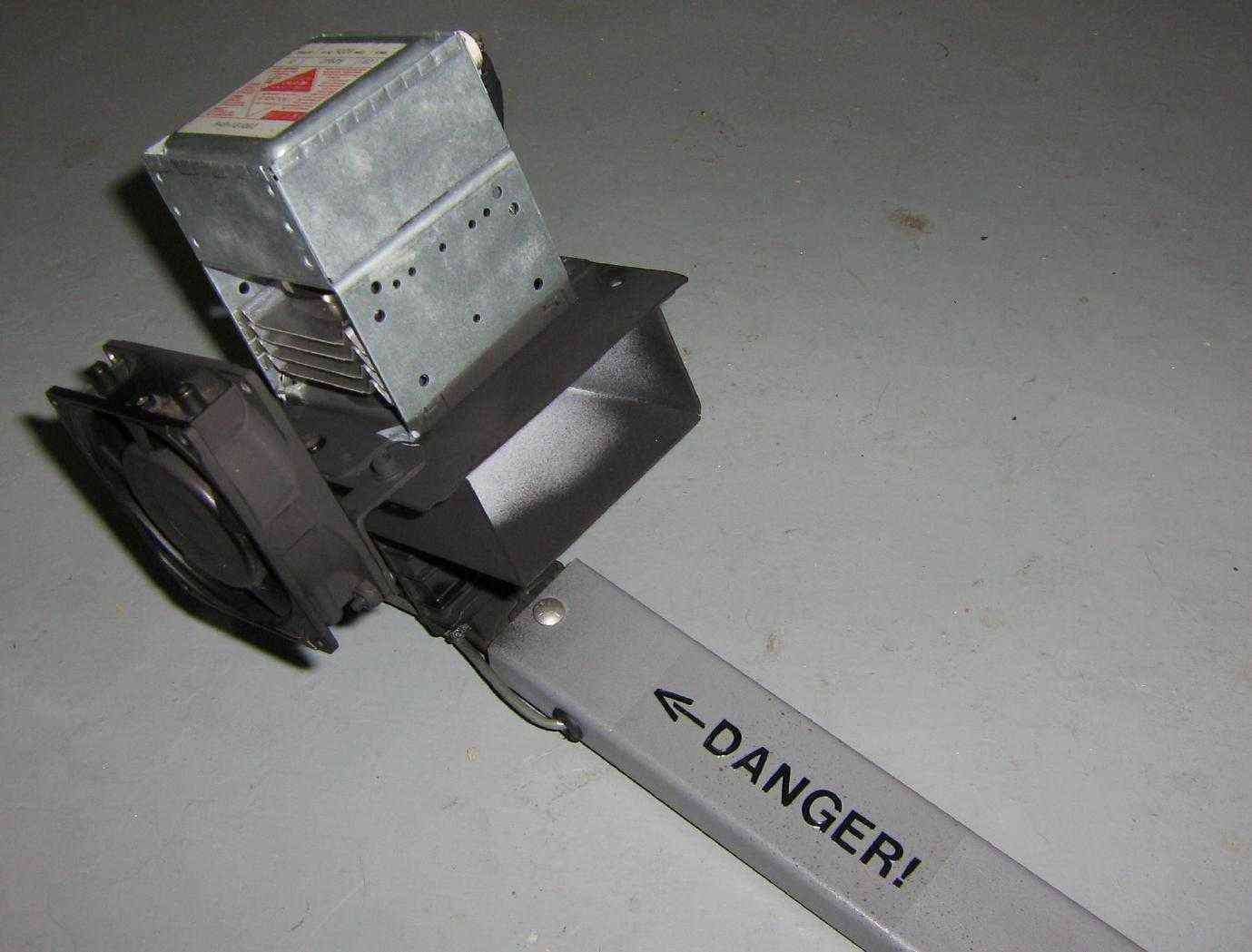
Use a Dremel tool to cut off or trim down the extra metal bits on the waveguide assembly.
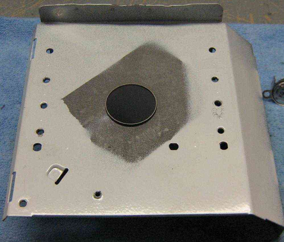
The magnetron will be mounted on an old 18-inch satellite dish antenna. Salvage the low-noise block downconverter, cut off the off the "horn" section, and file it down to it is smooth and level. Make it resemble something like the above photo.
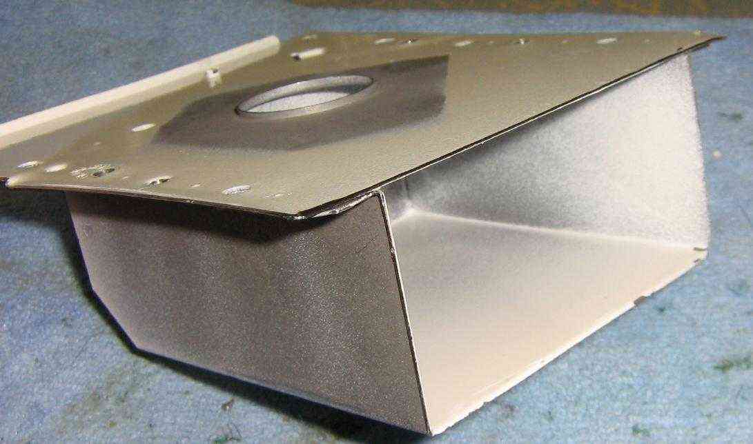
Then, using some two-part epoxy putty, attach the modified low-noise block downconverter to the rear of the waveguide assembly. Be sure to scrap down any paint so the epoxy is applied to a clean metal surface.
Side view. A coat of flat black spray paint will make it look scary.
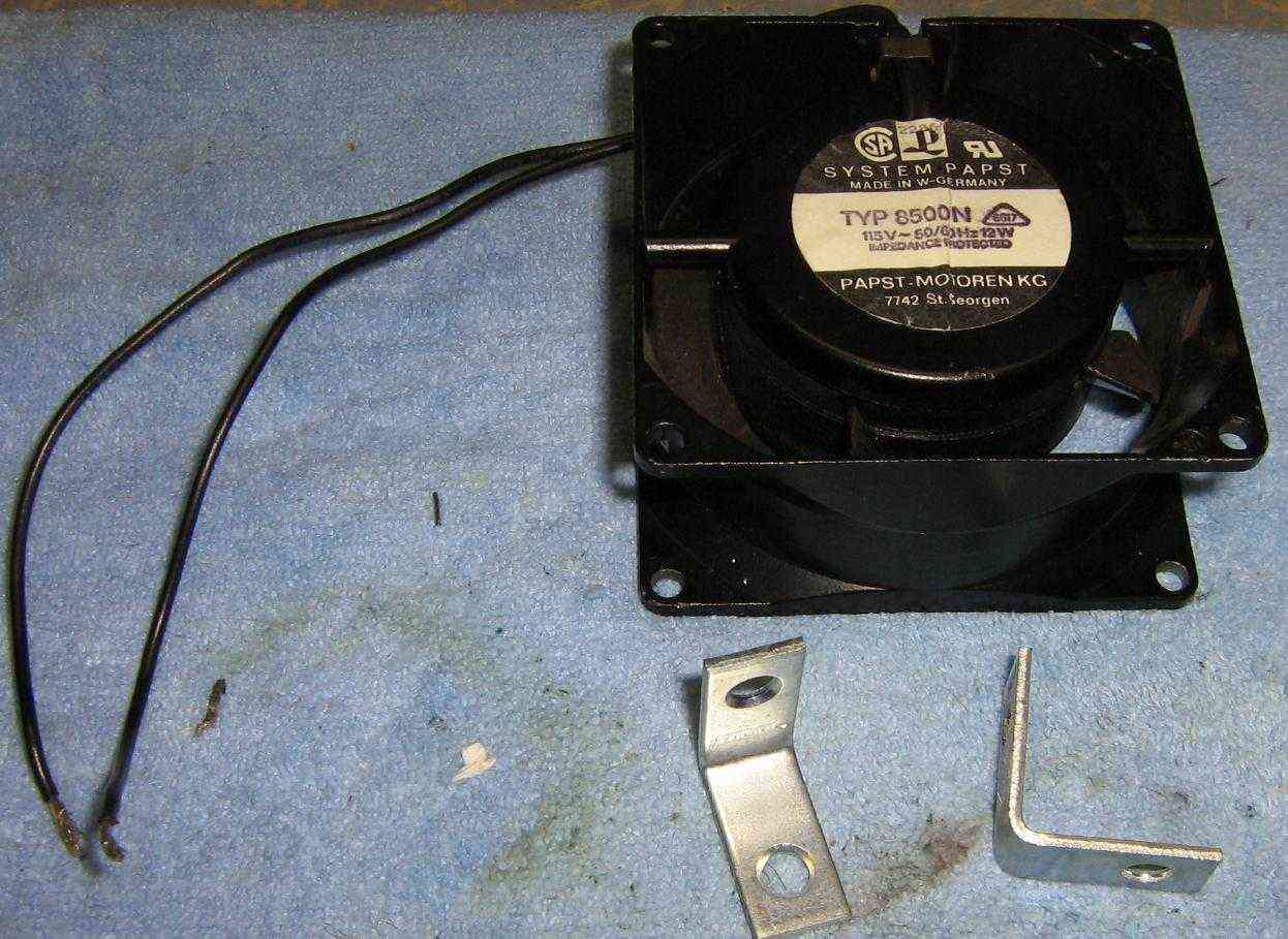
A fan should be mounted to cool off the magnetron when operated for long periods of time. 120 VAC fans will allow you to tap the incoming power. You may have to experiment with the fan mounting options, though.
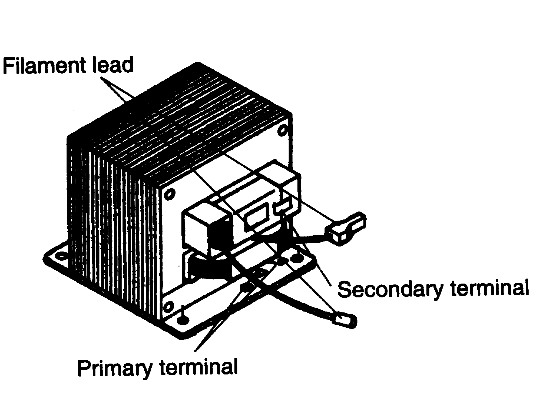
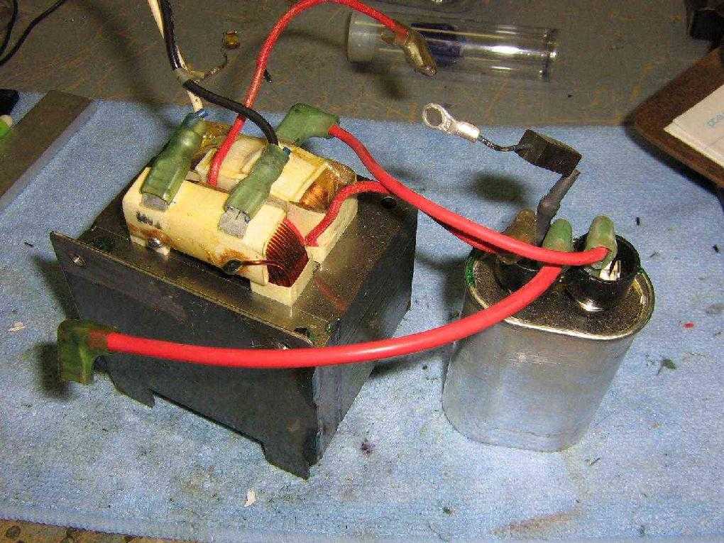
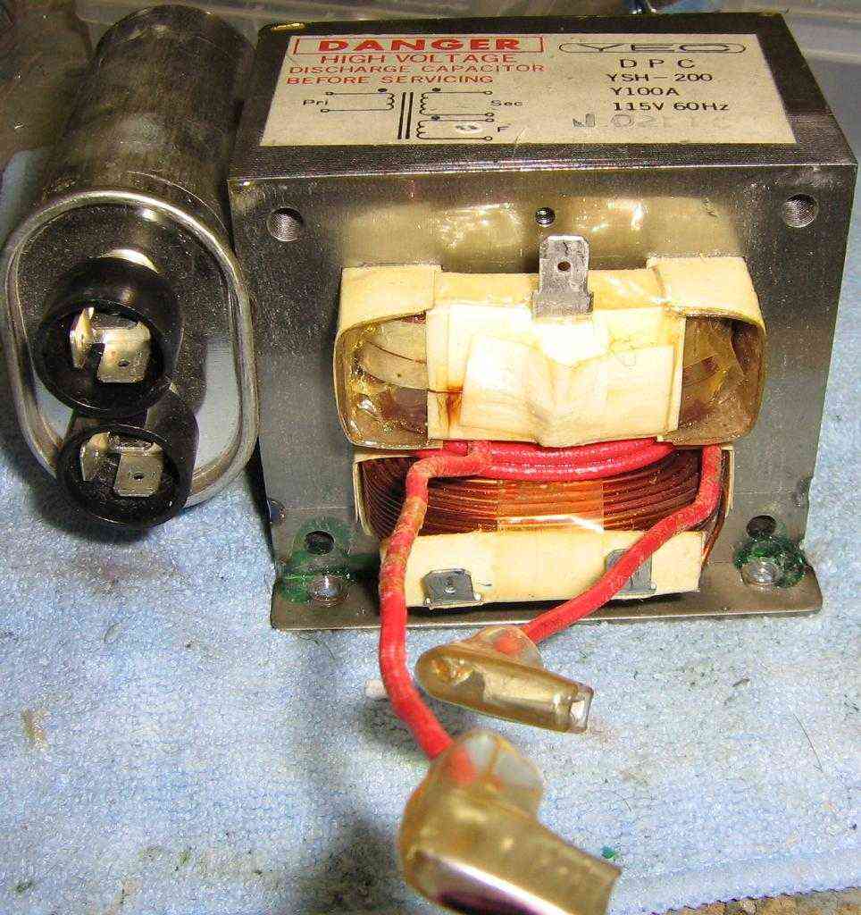
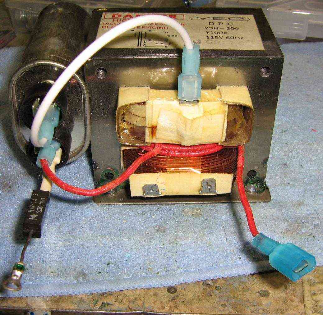
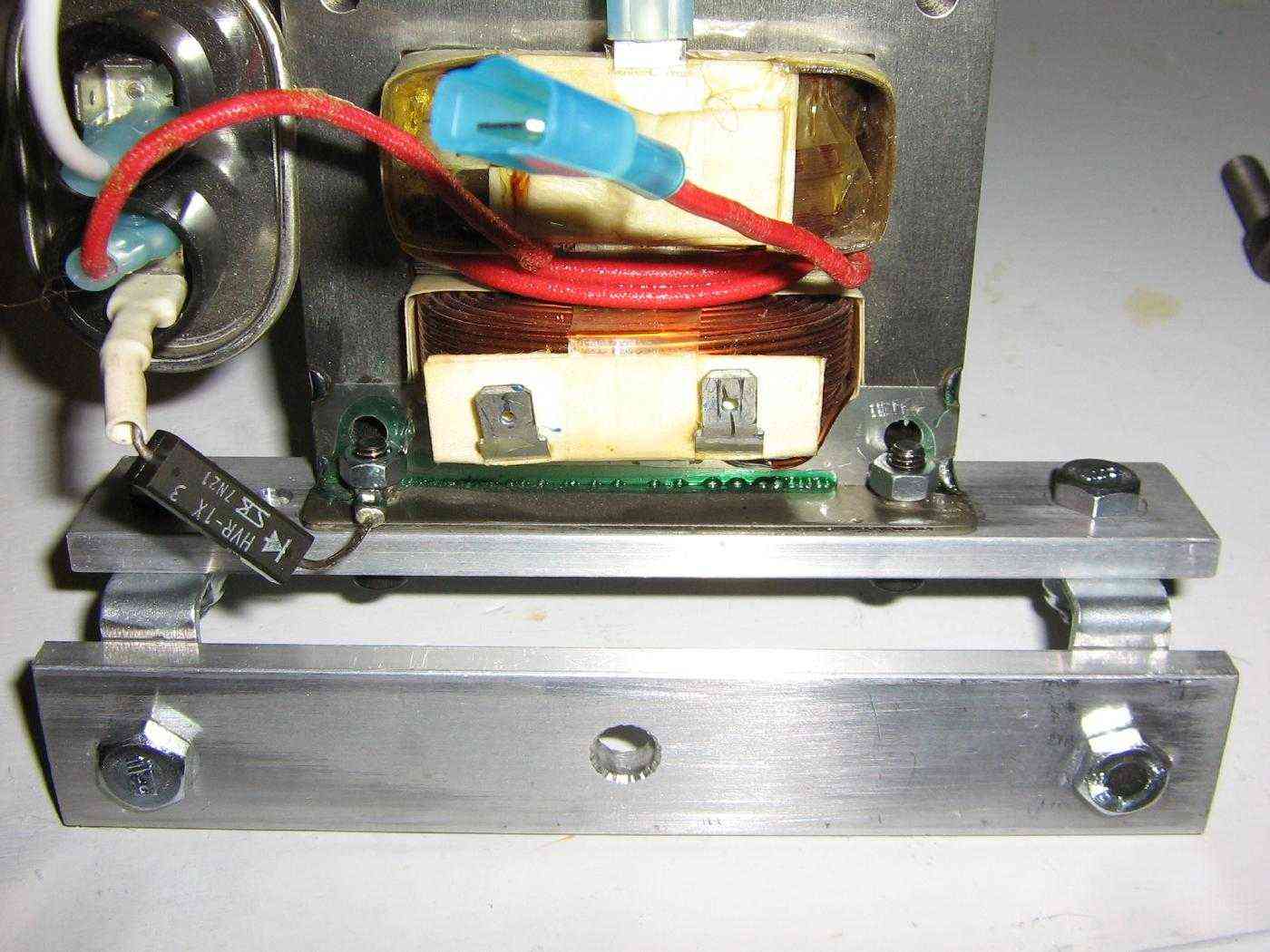
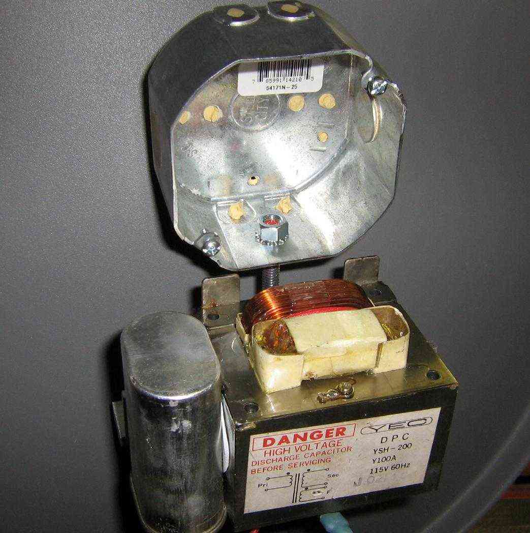
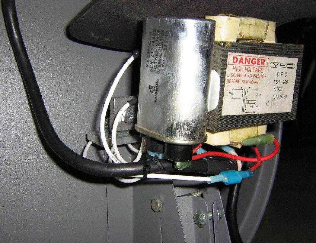
Stock power supply from the microwave oven. This current-limited high-voltage transformer has two secondary windings. One generates around 2,000 VAC from the incoming (primary) 120 VAC. A half-wave voltage doubler circuit consisting of a capacitor and a diode will boost this up to around 4,000 VAC. A separate secondary winding on the transformer provides the 3 VAC heater current. All microwave oven power supplies will be essentially the same, and you can swap out any components if they are bad.
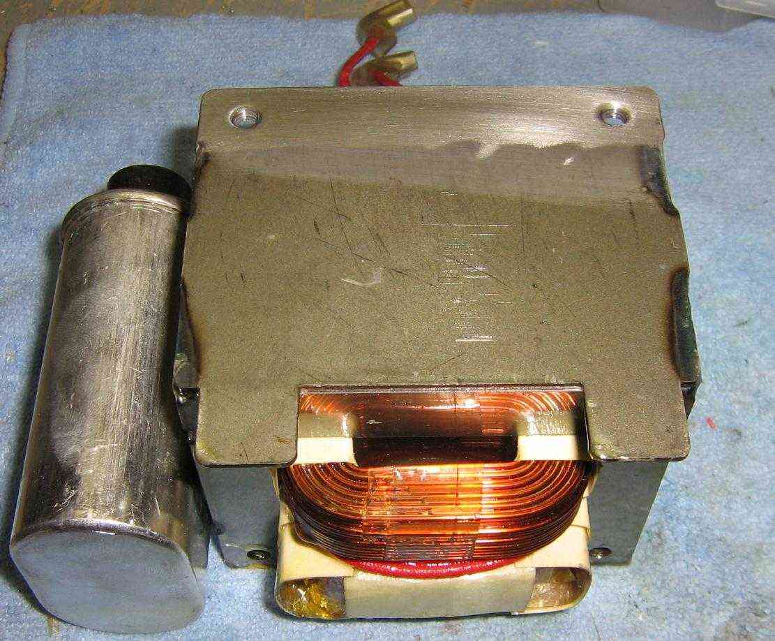
Bottom view of the high-voltage transformer. Note how the protective conformal coating has been removed around the mounting holes. This will provide a good ground for the transformer. A good ground system is required for this project to work properly!
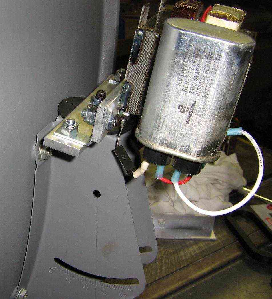
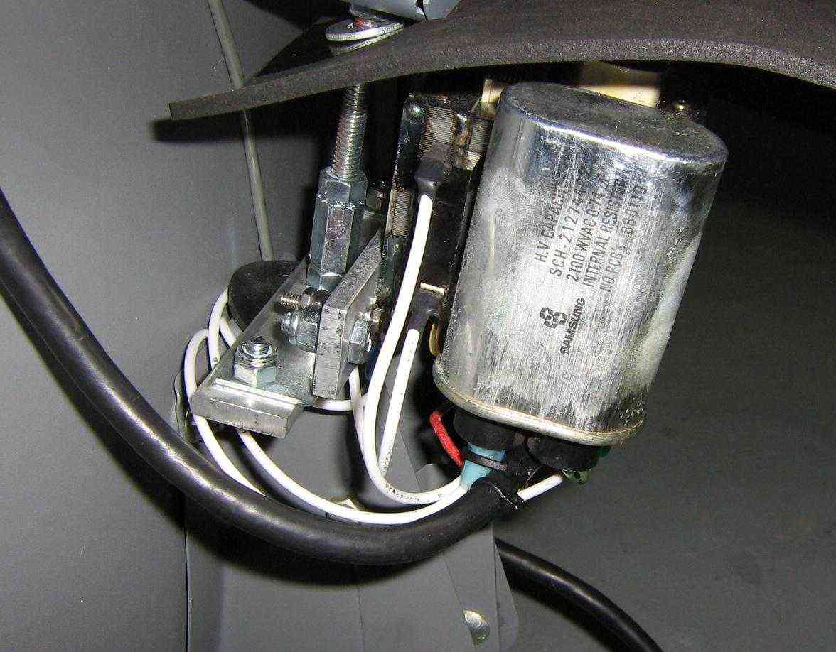
Transformer's terminal view. The high-voltage capacitor is epoxied to the side of the transformer. Most newer high-voltage capacitors will have an internal 10 megaohm resistor to bleed off any stray high-voltage. One side of the high-voltage secondary winding is tied to the transformer's metal case (ground). The center terminal is the 2,000 VAC output. The winding with the red cloth wire is for the 3 VAC heater output. The two spade terminals on the bottom are for the transformer's 120 VAC input.
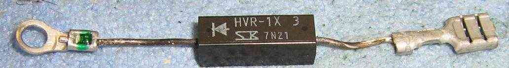
High-voltage diode. The cathode is tied to ground.
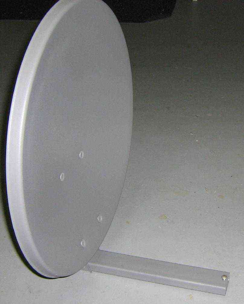
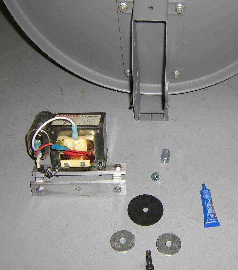
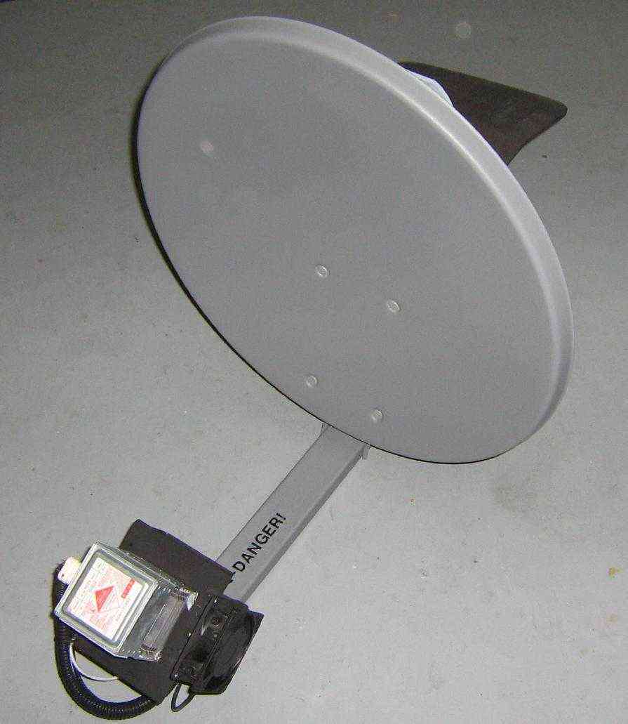
Overview of the satellite dish which will be used for this project.
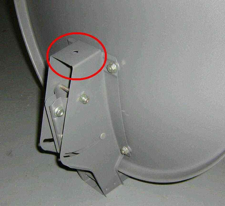
Rear view of the satellite dish showing its mounting bracket. Note the hole which will be used to hold the high-voltage transformer and support hardware.
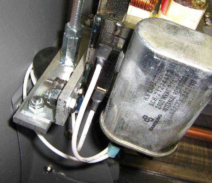
High-voltage transformer wire connections. The capacitor will be in series with the transformer's high-voltage secondary output. The high-voltage doubler diode will be grounded to the transformer's case.
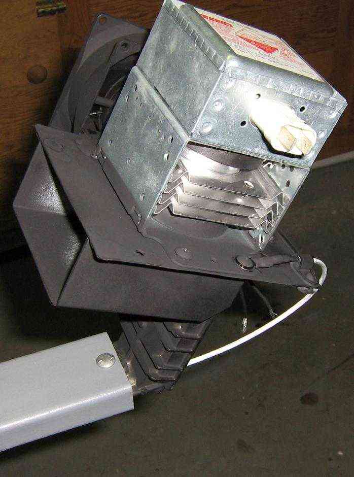
Mounting the magnetron onto the satellite dish. Note the ground wire connected to the waveguide assembly. The magnetron and the high-voltage power supply should share a common ground. This is very important!
Also, all the wires going to the magnetron are run inside the satellite's feed arm. You'll have to drill some holes in the downconverter mount to allow the wires to pass through.
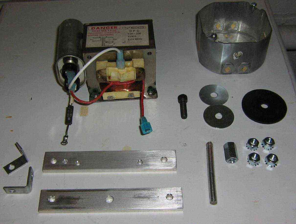
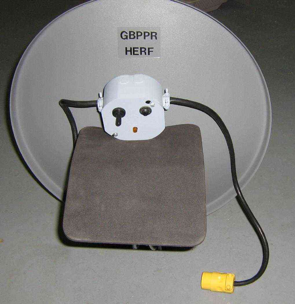
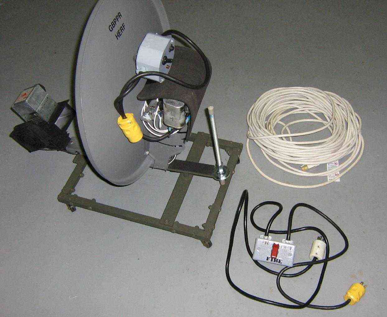
Overview of the hardware used to mount the high-voltage power supply to the back of the satellite dish. Starting from the bottom-left; two 1/2-inch L-brackets, two 6-inch long pieces of aluminium stock, a 3-inch piece of 5/16-inch threaded rod, a 5/16-inch coupler and nuts, above that is a 5/16-inch bolt, two flat washers, and one large rubber washer. An octagon electrical box will hold a secondary safety switch, a 15 amp resettable fuse, and a neon light indicator.
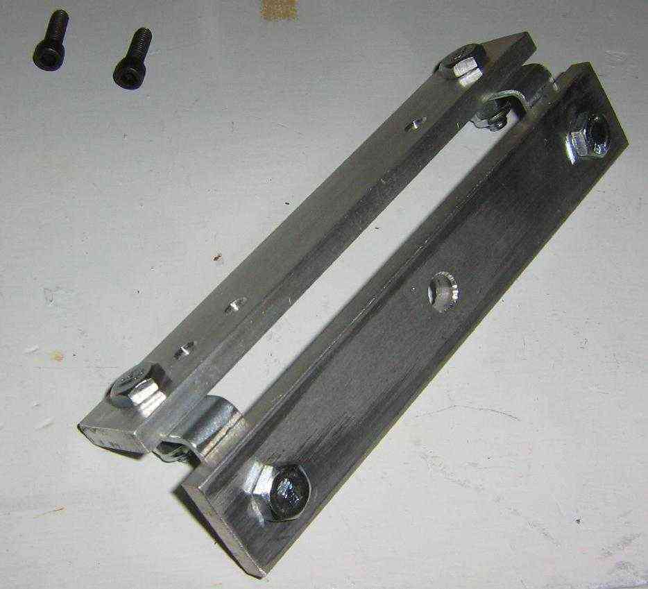
Arrange the two 6-inch long pieces of aluminium stock like so, using the L-brackets. This will be the mount for the high-voltage transformer, which will be fairly heavy. It will also act as a common ground wiring block.
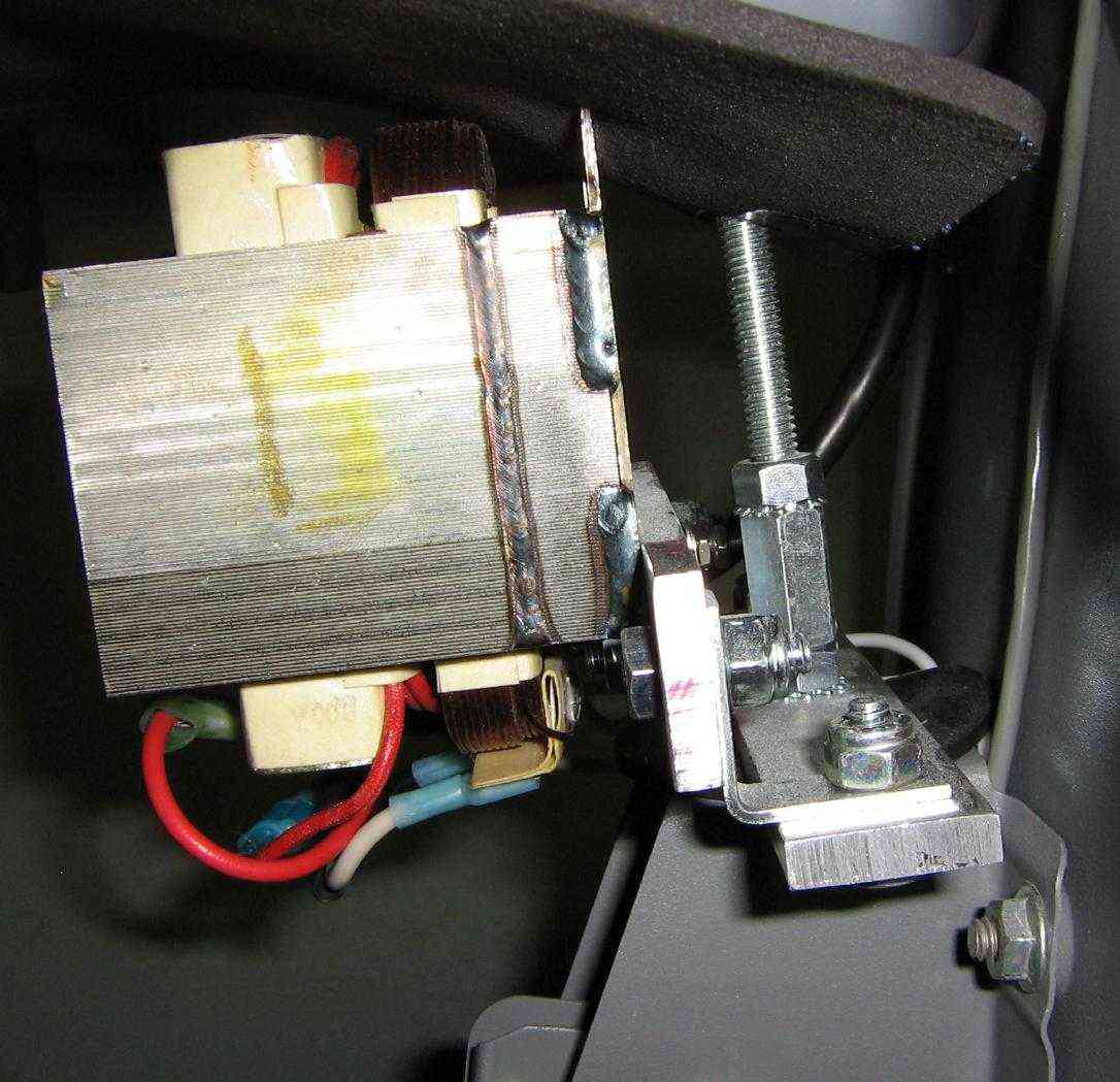
Picture showing the transformer bolted onto the mounting bracket. Note the high-voltage diode connected to a common ground.
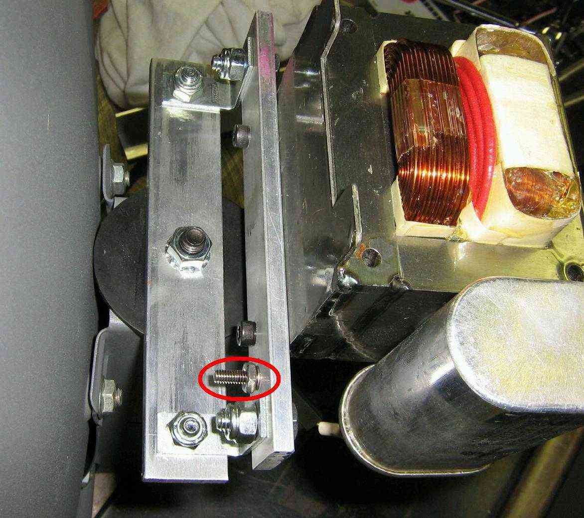
Preparing to mount the transformer onto the back of the satellite dish. The hardware should attach as follows; from the bottom of the satellite's mounting hole (circled in the past photo), place the 5/16-inch diameter bolt with two flat washers. This is needed to strengthen the flimsy metal on the dish. On the top of the mounting hole place the rubber washer followed by the aluminium transformer mounting block. Screw all that down with a 5/16-inch nut and follow it with a coupler.
Here is a top view of all that. The exposed #8 bolt will be used for grounding purposes.
Alternate view.
Drill a hole in the octagon electrical box and mount it as so using the 3-inch long piece of 5/16-inch threaded rod and a nut.
Alternate view. The old high-voltage diode was replaced with one which uses spade lugs. This helps to eliminate the chance of an exposed high-voltage lead.
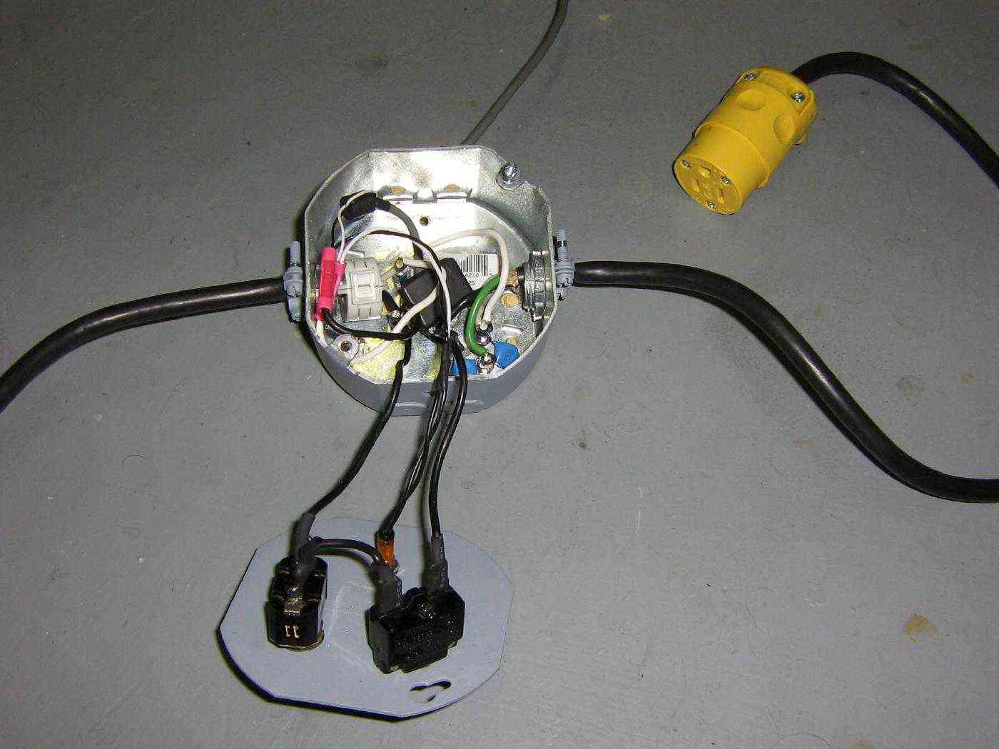
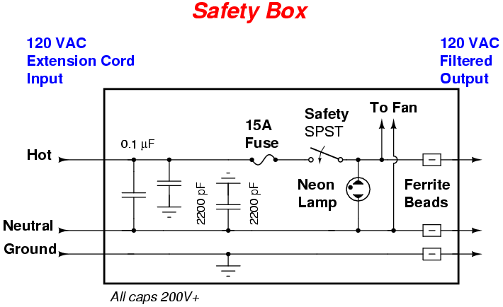
Inside the octagon electrical box. The incoming 120 VAC line passes through a simple capacitor filter, a 15 amp resettable fuse, and finally through a safety switch. The safety switch prevents the HERF device from operating if accidently plug it.
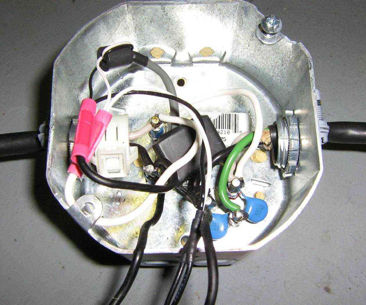
Closeup view of the octagon electrical box. The incoming 120 VAC is on the right. The two blue capacitors are 2200 pF and the large, black square thing is a 0.1 µF capacitor. There is a snap-on ferrite bead on the 120 VAC output.
View of the filament and cathode voltage lines going to the magnetron. They are soldered to the magnetron's spade lugs and covered with protective tubing.
DANGER!
Don't let Emmanuel Goldstein near your little boys!
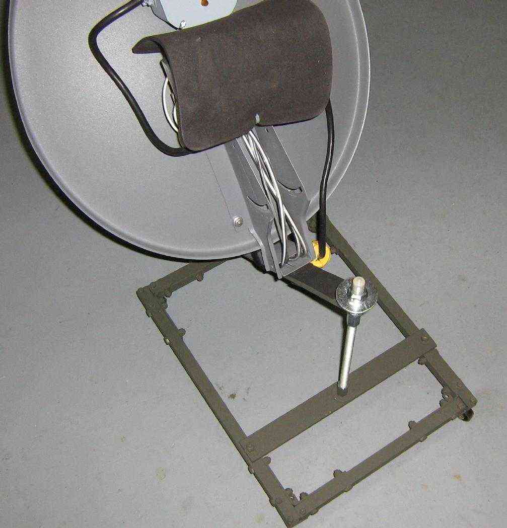
Top view of the magnetron connected to the satellite dish.
Final high-voltage transformer connections with all the wiring done. The transformer's filtered 120 VAC input is coming in from the left.
Side view. An old mouse pad is used to protect the transformer and any exposed wiring.
Completed top view. The 120 VAC input on the right goes to an extension cord.
Alternate side view.
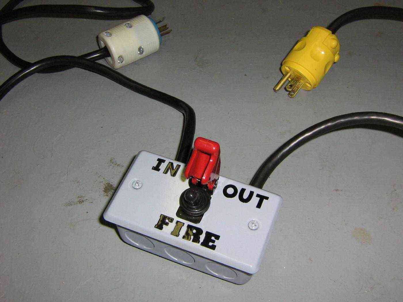
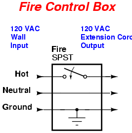
Fire control box. Unfiltered, "wall outlet" 120 VAC comes in on the left. A SPST switch is in series with the "hot" line. It then goes out the plug on the right, which will be connected to the HERF device using an extension cord.
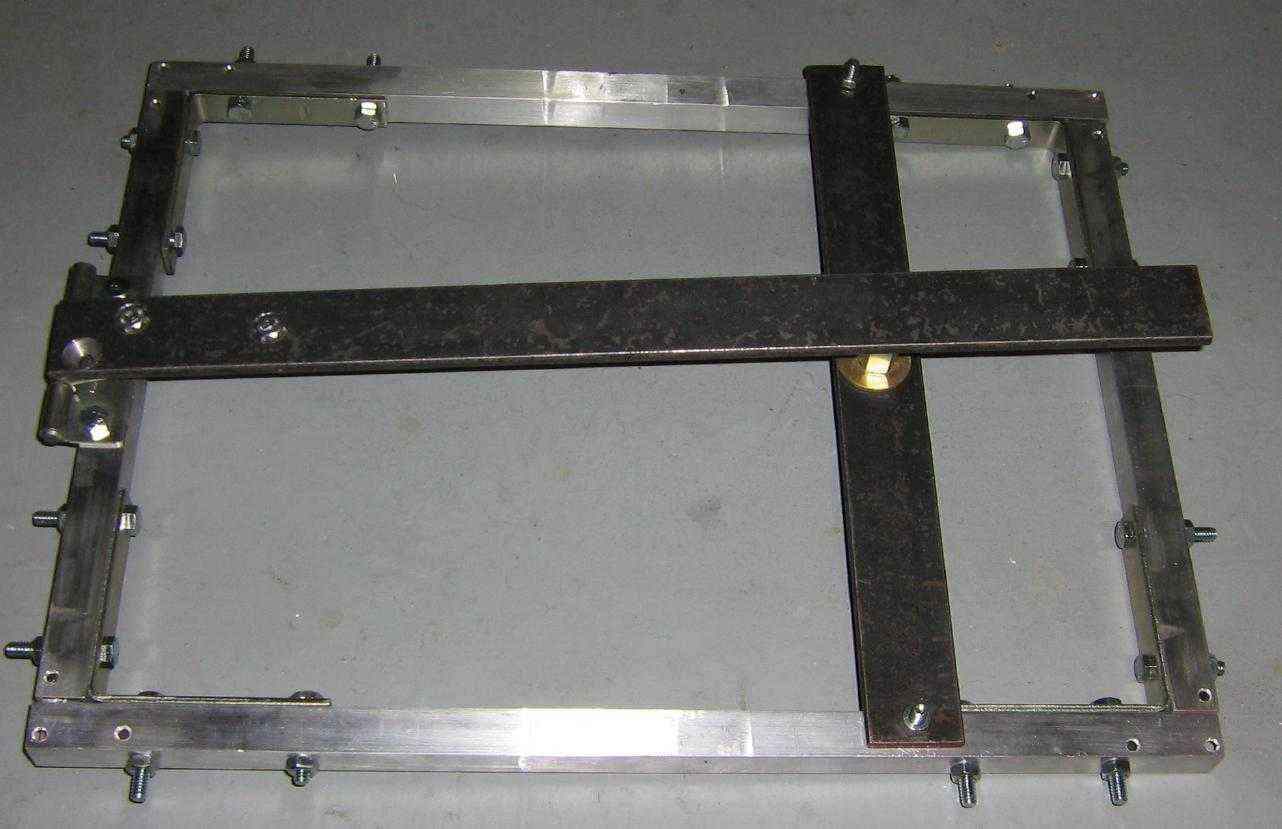
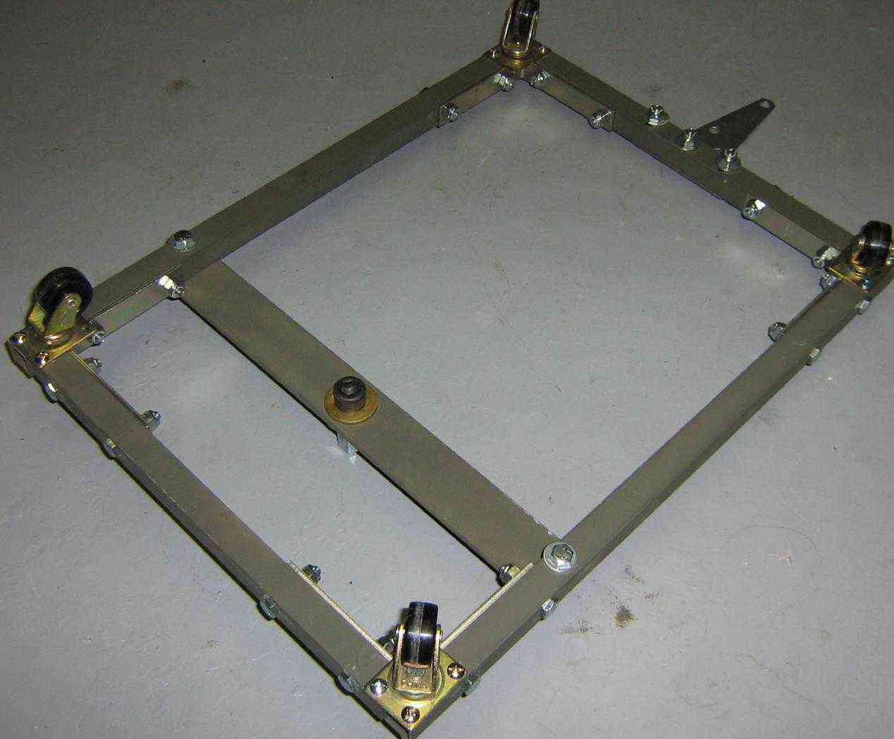
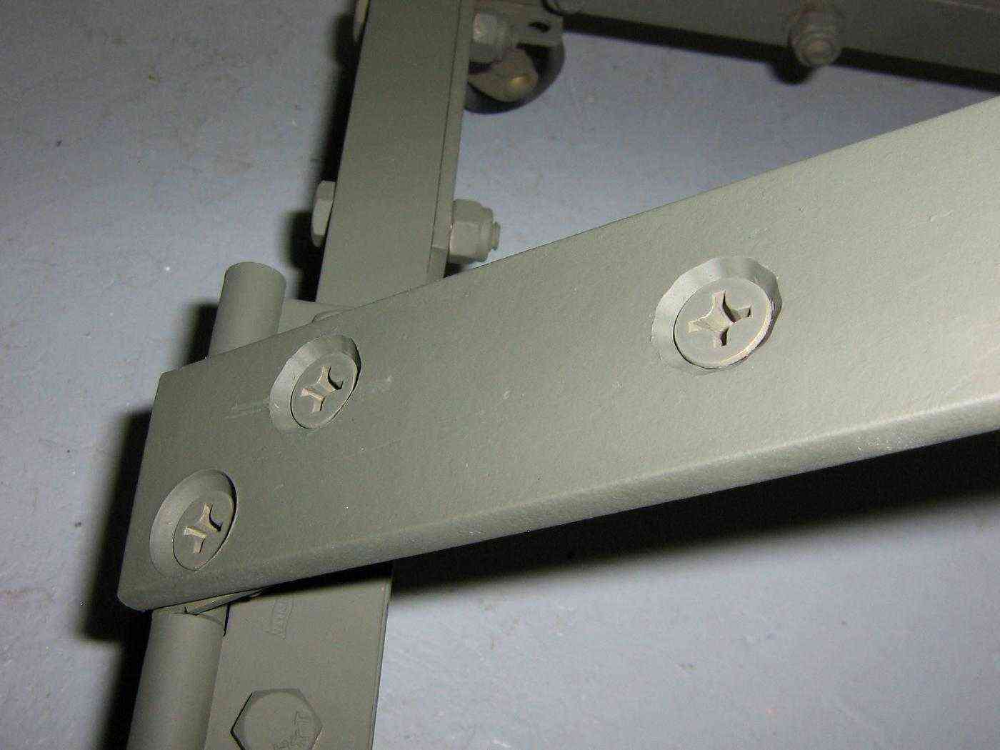
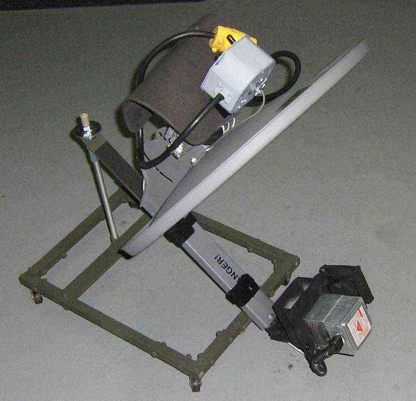
I made a little roller cart to push the HERF device around with. It is made from 3/4-inch square aluminium tube and 1.5-inch wide steel stock. L-brackets secure the corners. Yes, it's dumb.
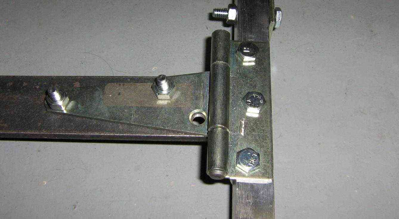
Hinge view. This will be useful for providing the "tilt" which is needed for the offset-feed on the satellite dish to be pointed toward the horizon. It also makes storage of the HERF device quite easy.
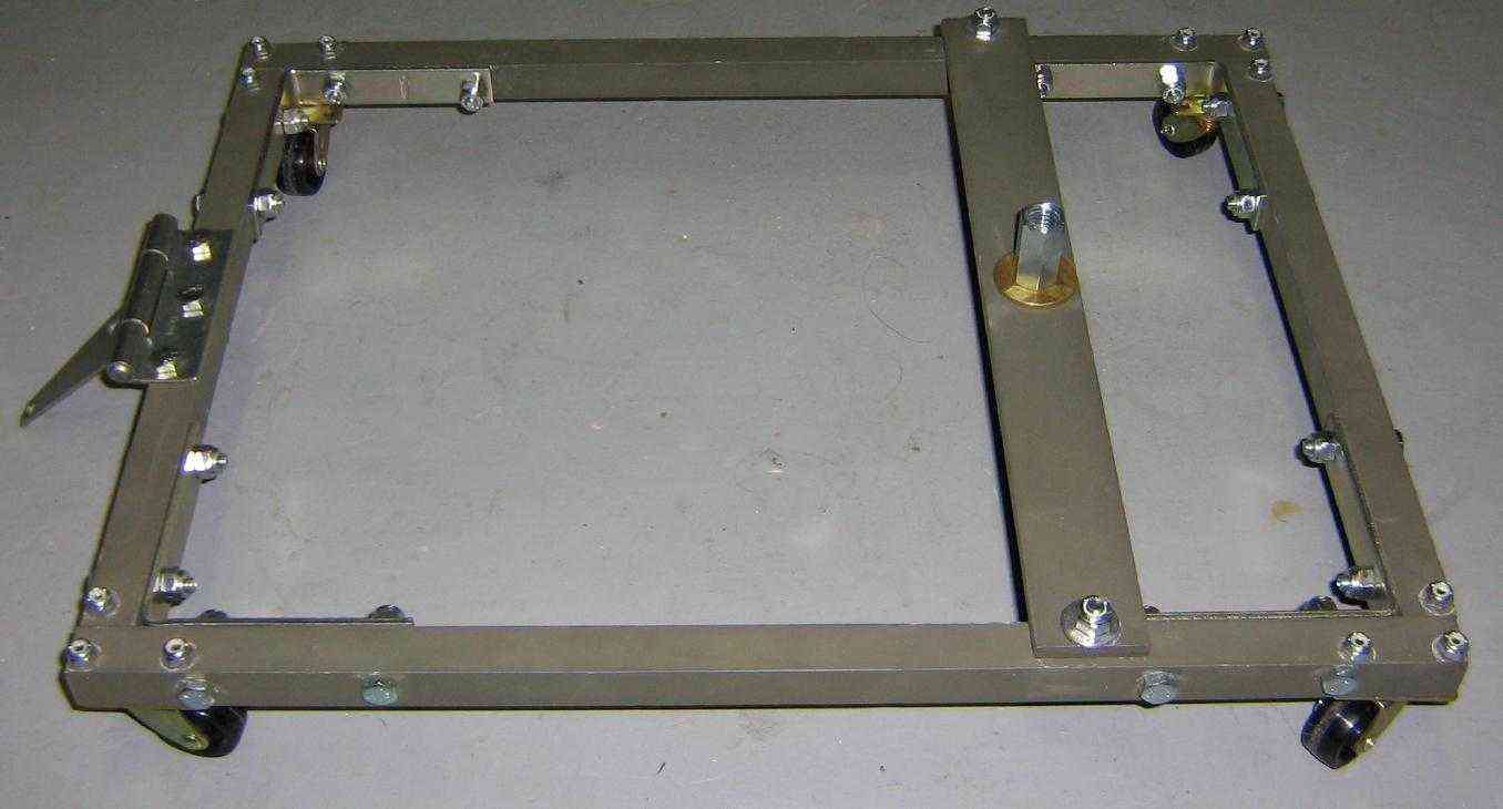
Completed view with some little wheels added.
Rear view of the cart.
Bottom view showing the wheels.
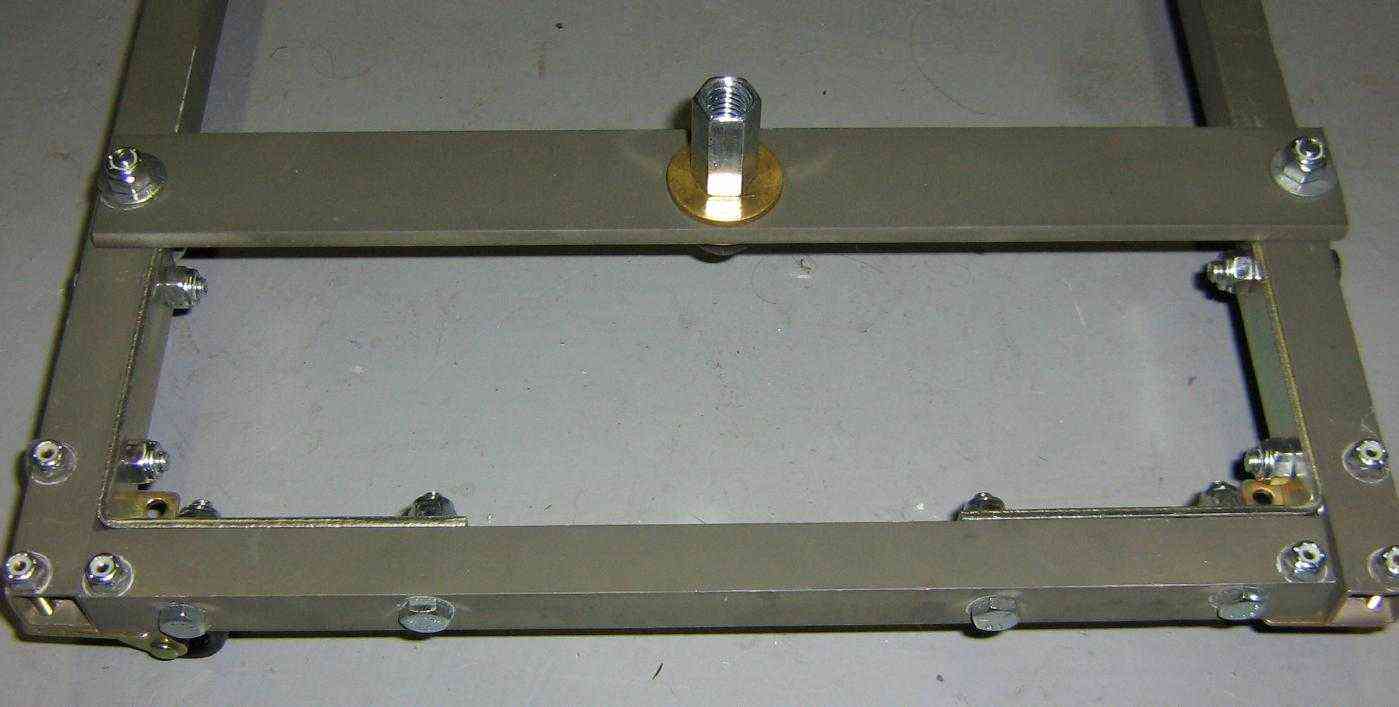
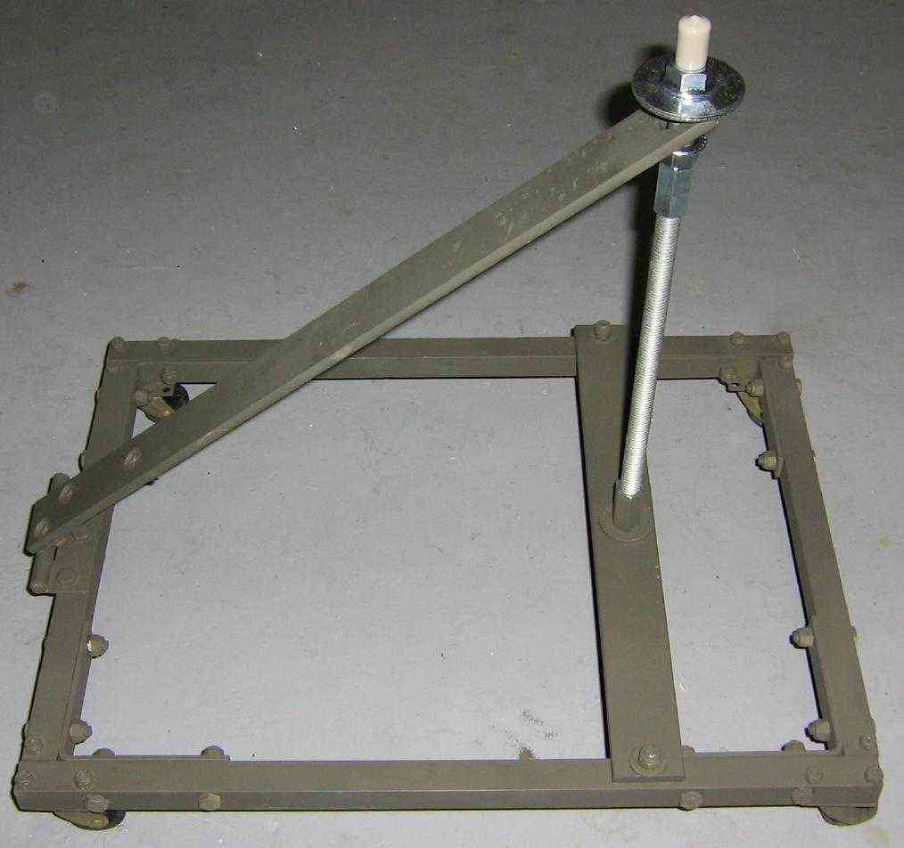
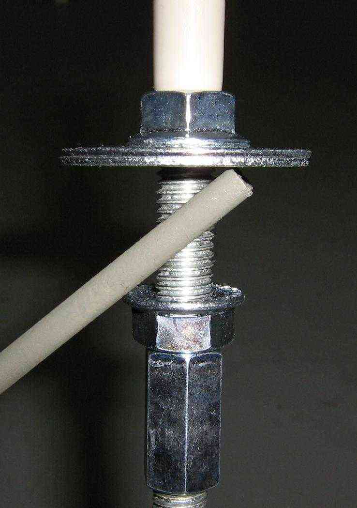
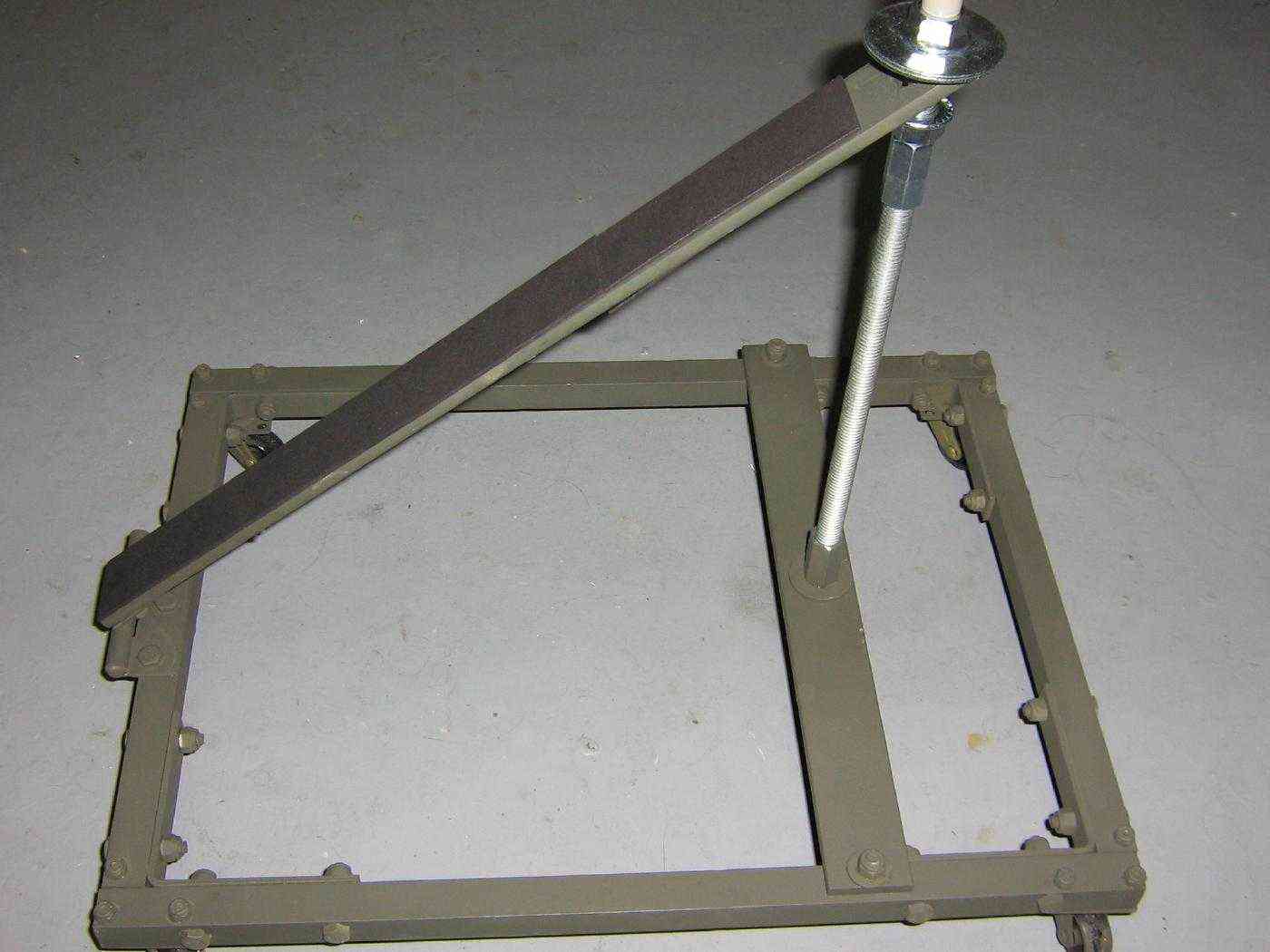
Cart with the tilt arm in position. You may wish to experiment around with the correct angle. A 1/2-inch diameter threaded rod, coupler, washers, and nuts secure the tilt arm. There is a little protective cap on top of the threaded rod.
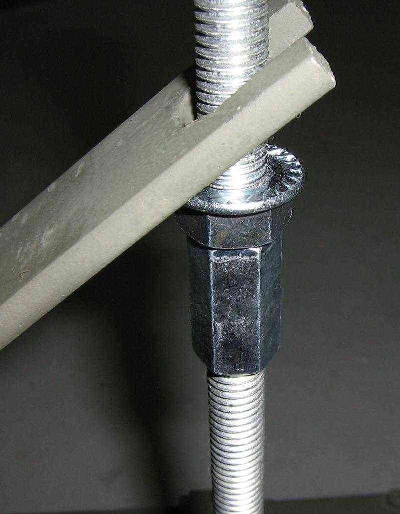
Closeup view of the tilt arm connection. A large notch was cut out of the arm. It is held in place with some 1/2-inch hardware.
Tilt arm locked in place. Yes, it's retarded, but it works.
Tilt arm is attached to the hinge with some countersunk bolts.
Completed cart overview. Some art foam protects the HERF device from the tilt arm.
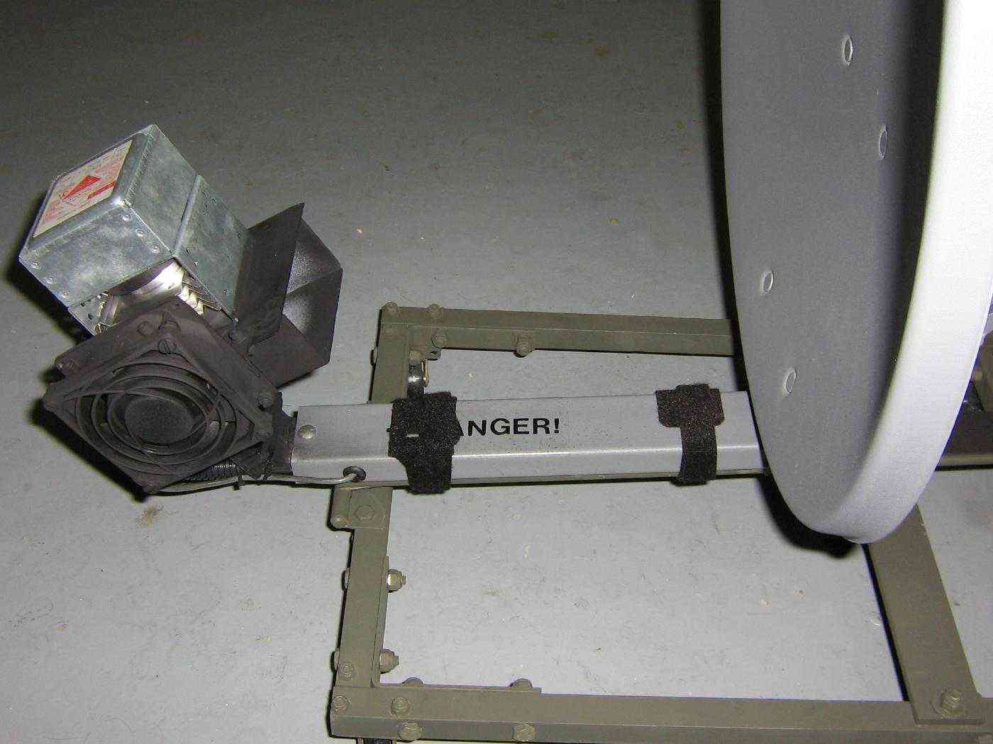
The HERF device is secured to the tilt arm using Velcro straps. This allows for the HERF device to be quickly attached and removed. It's probably not a good idea to drill too many holes into the satellite dish's feed arm.
Rear view. The high-voltage wires going to the magnetron are passed through some 1/4-inch vinyl tubing for additional protection.
Alternate view. The satellite dish needs to be tilted forward to be aimed at the horizon.
Practice makes perfect!
Stowed position, shown with a 40 foot extension cord.
If you are wondering, it feels like walking in front of a fire!!!!
Schematics
Notes
- Higher resolution pictures and the original project article are available in GBPPR 'Zine Issue #29
- National 870 Watt, 2.45 GHz Magnetron (344k PDF)
- Almost Complete, Unofficial HERF and Other Radio Weapons Information Page
- Winn Schwartau - HERF Guns, EMP Bombs and Weapons of Mass Disruption Defcon 7 (9.6M MP3)
- Sinister - Radio Energy Weapons Defcon 8 (17.4M MP3)
- The Wireless Threat to Our Electronic Infrastructure
- Lightning Bugs
- The Dawn of the E-Bomb
- Microwave Cannon
- HERF Gun: Make it in Your Basement Note: Slashdot posters are the dumbest people in the world.
- HEMP and Radio Frequency Threats to Government and Industry: Fact or Fiction?
- High-Power Microwave Weapons - Full Power Ahead?
- EMP Radiation from Nuclear Space Bursts in 1962
- Engineering and Design - Electromagnetic Pulse (EMP) and TEMPEST Protection for Facilities
- EMP Weapons to Shoot Down UFOs
- Mom Killed Baby Niglet in Microwave Oven
- "Lightning Machine" at Chicago's Museum of Science & Industry?
- Knocking Out Noise Article about Barney Vincelette's HERF device. (Mirror)
- Dielectric Properties of Body Tissues 10 Hz - 100 GHz
- HERF Operation
- HERF Gun Zaps More Than Your Dinner Hack a Day entry.
- Cultural Hygiene Machines by Dr. Barney Vincelette
- Design of a 95 GHz, Multi-Megawatt Gyroklystron Amplifier for Advanced Accelerators (185k PDF)
Other Related GBPPR Projects:
- GBPPR Electromagnetic Pulse Experiments - Part 1
- GBPPR Electromagnetic Pulse Experiments - Part 2
- GBPPR Electromagnetic Pulse Experiments - Part 3
- GBPPR Microwave Oven Experiments
- GBPPR Active Denial System
- GBPPR Radar Experiments
