This is a simple project for a RF phase detector which can be used at frequencies up to 2.7 GHz. RF phase detectors are designed to compare the phase (or magnitude) relationship between two incoming RF signals. Observing the phase or magnitude of two RF signals (incoming and outgoing) is very useful when analyzing the impedance match of a RF amplifier, mixer, or other RF stage. But, for this application, we'll be using it for an upcoming phase-detecting microwave interferometer surveillance device project.
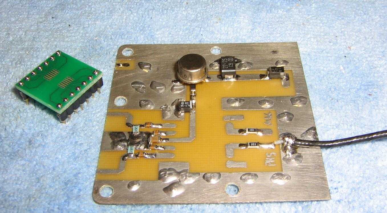
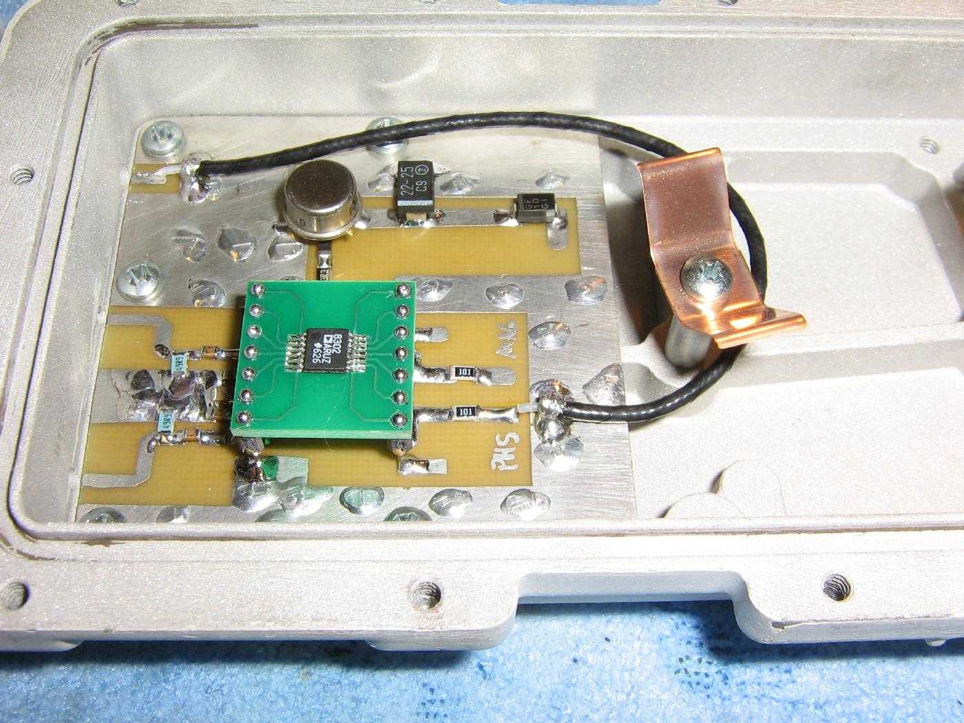
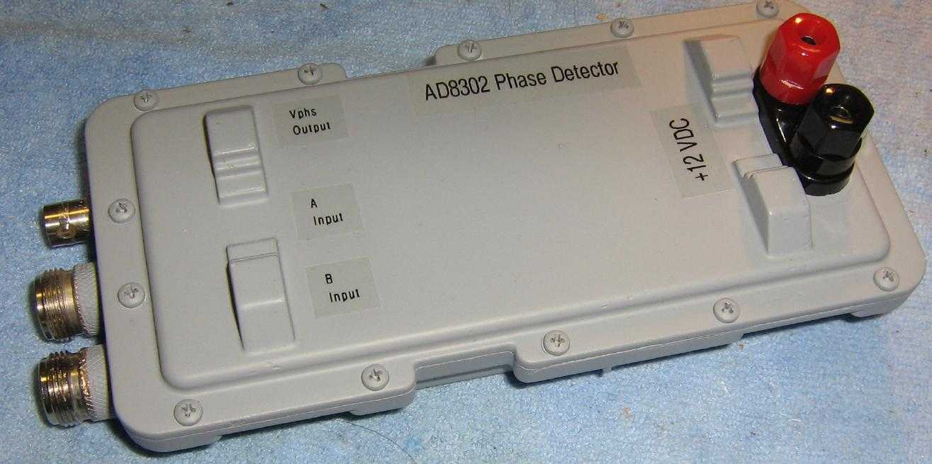
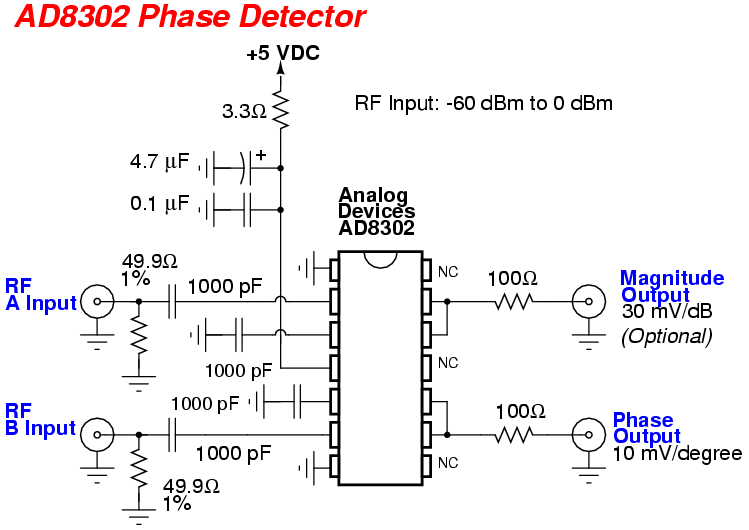
This phase detector project will be based around an Analog Devices AD8302 LF-2.7 GHz RF/IF Gain and Phase Detector. It's available from Digi-Key for under $20. If you ask nicely, you may get one as a free sample from Analog Devices. The AD8302 is in a 14-pin TSSOP package, so you may wish to also get a 14-pin TSSOP-to-DIP adapter board.
The Analog Devices AD8302 is really a quite remarkable device, only requiring a few passive external components for operation. This little chip basically gives the same phase and magnitude relationship information which a multi-thousand dollar RF vector network analyzer would give.
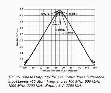
We'll only be using the phase difference output information in this project. The AD8302 provides an accurate measurement of phase over a 0° to 180° range which is scaled to a 10 mV/degree voltage output. This works out to an output range of 0 to 1.8 volts. Unfortunately, the AD8302 doesn't distinguish the sign of this phase relatioship. For example, a -45° and a +45 phase difference would both give the same output voltage.
Refer to Figure TPC 25 "Phase Output vs. Input Phase Difference" from the AD8302's datasheet for a visual display of the phase output information. A 0° phase difference between the two incoming RF signals should give an output of around 1.7 to 1.8 volts.
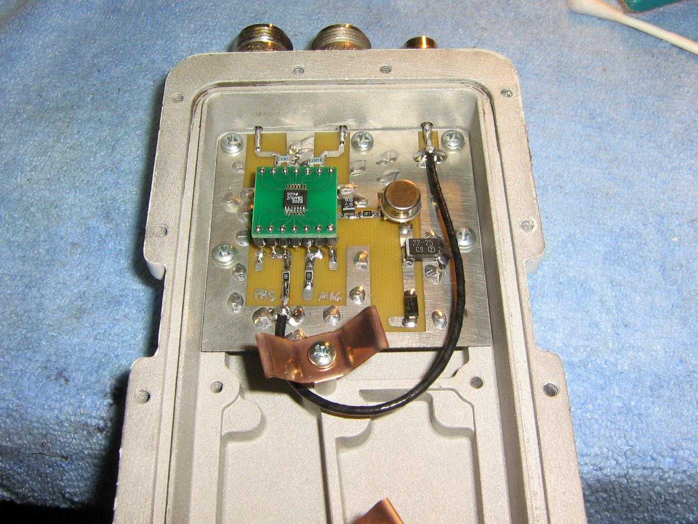
In our microwave interferometer surveillance project, the phase detector will be used to measure the difference in phase relationship between the transmitted and received microwave RF beams. This should, theoretically, allow us to remotely detect sub-millimeter vibrations as the slight shift in phase response between these two RF beams.