Originally appeared at http://www.security-forums.com (Mirror)
Overview
A post on www.security-forums.com (Mirror) on making homebrew digital data taps by M3DU54 recently caught my attention. His particular project involved intercepting the keystroke signals as they are being sent to the keyboard and transmitting them to a remote monitoring post using only a simple Microchip PIC microcontroller and a low-cost transmitter module. This would be very useful for intelligence operations against terrorists, ACLU lawyers, nutcases, etc. as they tend to use public computers.
M3DU54's posts are very in-depth and informative. Be sure to re-read them several times before beginning this project.
The version which is covered here will vary slightly from the design by M3DU54. The Linx Technology transmitter and receiver modules can be ordered from Digi-Key and the PIC16F84A-20 and the passive components can be ordered from either Digi-Key or Mouser.
Transmitter Schematic & Construction Notes
Wireless Keystroke Data Tap - Transmitter Schematic
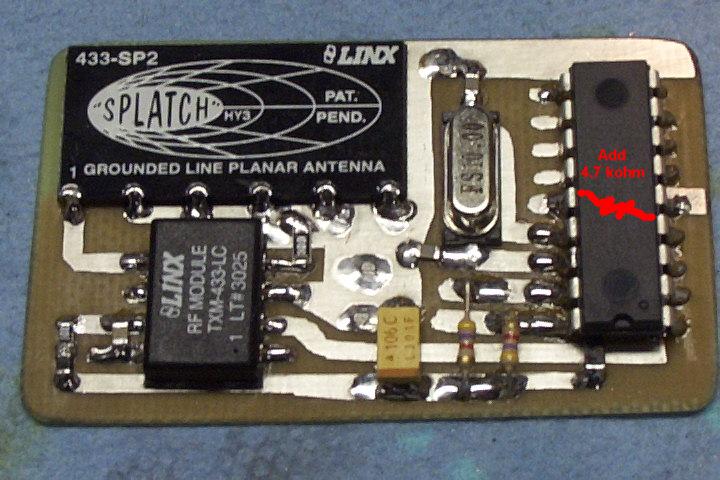
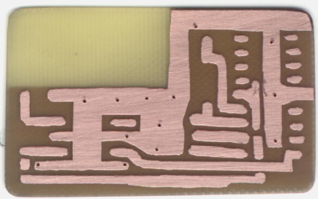
Wireless Keystroke Data Tap - Transmitter PC Board Layout (An error on this layout is I forget the 4.7 kohm pull-up resistor on pin-4 of the PIC)
The Microchip 16F84A-20 8-bit Microcontroller is Digi-Key Part Number: PIC16F84A-20/P-ND for the 18-pin DIP version.
The Linx Technology TXM-433-LC Transmitter Module is Digi-Key Part Number: TXM-433-LC-ND for the SMT version.
The Linx Technology 433-SP2 Splatch Antenna is Digi-Key Part Number: ANT-433-SP-ND for the SMT version.
The 10 MHz Crystal Oscillator is Digi-Key Part Number: 300-6121-1-ND for the SMT version. Loading capacitors should be between 18 pF and 22 pF (NP0).
The other capacitors, resistors, and ferrite beads can be salvaged from old circuits boards.
433 MHz was chosen for this particular data tap because it allows the use of standard 440 MHz amateur radio Yagi antennas, filters, and pre-amplifiers on the remote receiver. This can be used to significantly increase the data interception range.
A resistor on pin-5 of the TXM-433-LC transmitter module can be used to reduce the transmitter's RF output power. This can be tweaked to reduce overall current draw, or to prevent the transmitter from transmitting too far. A 0-ohm jumper is shown in the picture for maximum transmitter output power.
Be sure there is no ground plane beneath the Splatch antenna. Also try to mount the antenna away from any metal objects when planting the data tap.
The keyboard's Vcc line is capable of sourcing up to 100 mA. It is possible to connect the output of the transmitter module up to a small MMIC amplifier and boost the RF output power up to around 500 mW.
PIC16F84A Source Code
This source code comes from the Afrotech version of this project.
Experimental code with a few minor changes and set to run with a 4 MHz clock.
The C source code can be compiled using the CCS C Compliler for Microchip PICmicro MPUs. (Yes, they are the DDI people)
The PIC16F84A can be programmed using the infamous "No-Parts" PIC Programmer.
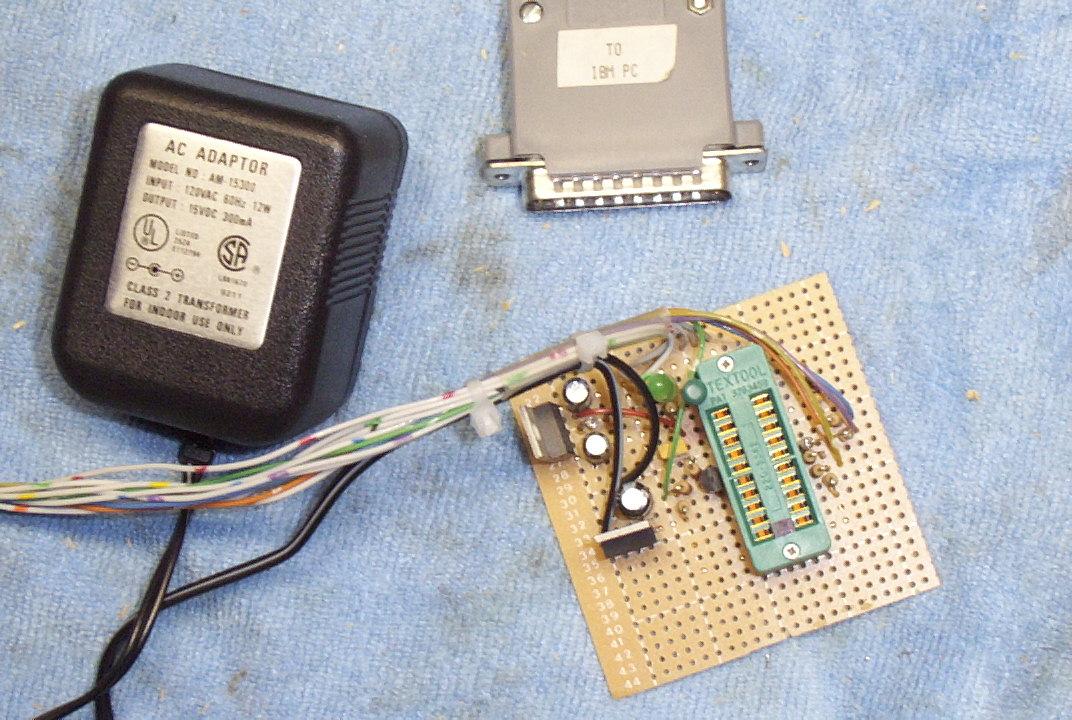
Here is a picture of my version of the "No-Parts" PIC Programmer. Be sure the 0.1 µF capacitor (C1 in the schematic) is very close to the Vdd pin (14) on the PIC16F84A. Look for wall-wart power supplies at Goodwill that output around +15 VDC, then regulate it down to +12.7 VDC and +5 VDC.
Receiver Schematic & Construction Notes
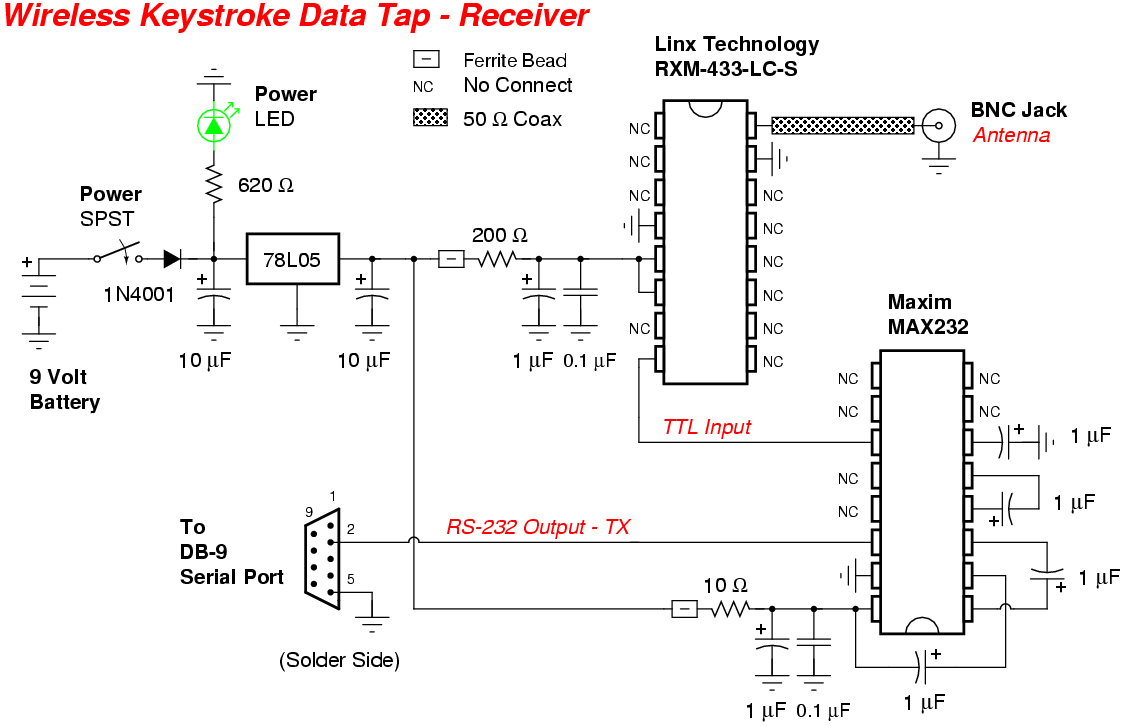
Wireless Keystroke Data Tap - Receiver Schematic
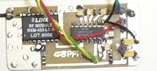
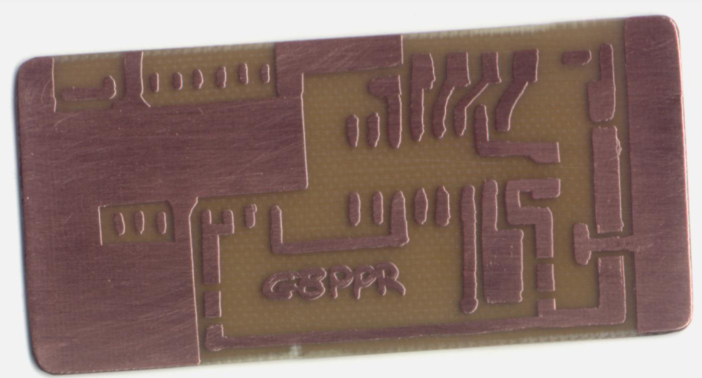
Wireless Keystroke Data Tap - Receiver PC Board Layout
The Maxim MAX232 RS-232 Driver/Receiver is Digi-Key Part Number: MAX232CPE-ND for the 16-pin DIP version.
The Linx Technology RXM-433-LC-S is Digi-Key Part Number: RXM-433-LC-S-ND for the SMT version.
The 78L05 Voltage Regulator is Digi-Key Part Number: LM78L05ACZNS-ND for the TO-92 version.
The other capacitors, resistors, and ferrite beads can be salvaged from old circuits boards.
The BNC jack and DB-9 serial port jack and cables are available from Radio Shack.
The datasheet for the receiver mentions that the support pads should not be connected to anything, so be sure they are isolated. The RXM-433-LC-S requires a 200 ohm dropping resistor if it is run from +5 VDC. It can be omitted if the RXM-433-LC-S is run at +3 VDC.
This particular version uses the more common Maxim MAX232 RS-232 Driver/Receiver. The MAX232 uses external capacitors, but it is not too hard to hook up. The MAX233 used in M3DU54's version will allow for much easier construction.
Directional UHF TV antennas work beautifully for those long-range operations.
Pictures
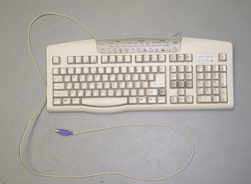
Overview of the keyboard which is going to be "bugged." It's one of those retarded "multi-media" versions, but it has alot of room inside it.
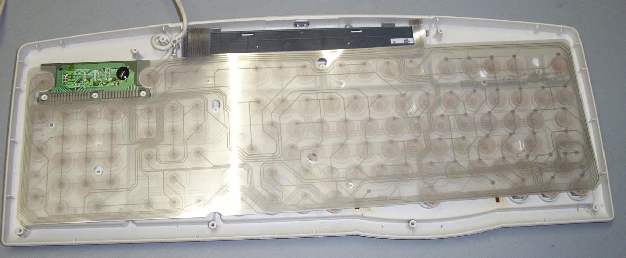
Rear internal view of the keyboard. Be sure not to lose any screws or any of those little rubber things.
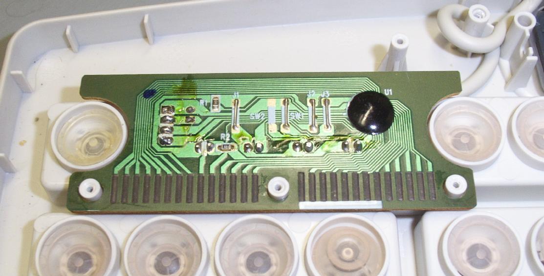
Closeup picture of the solder-side of the keyboard controller card.
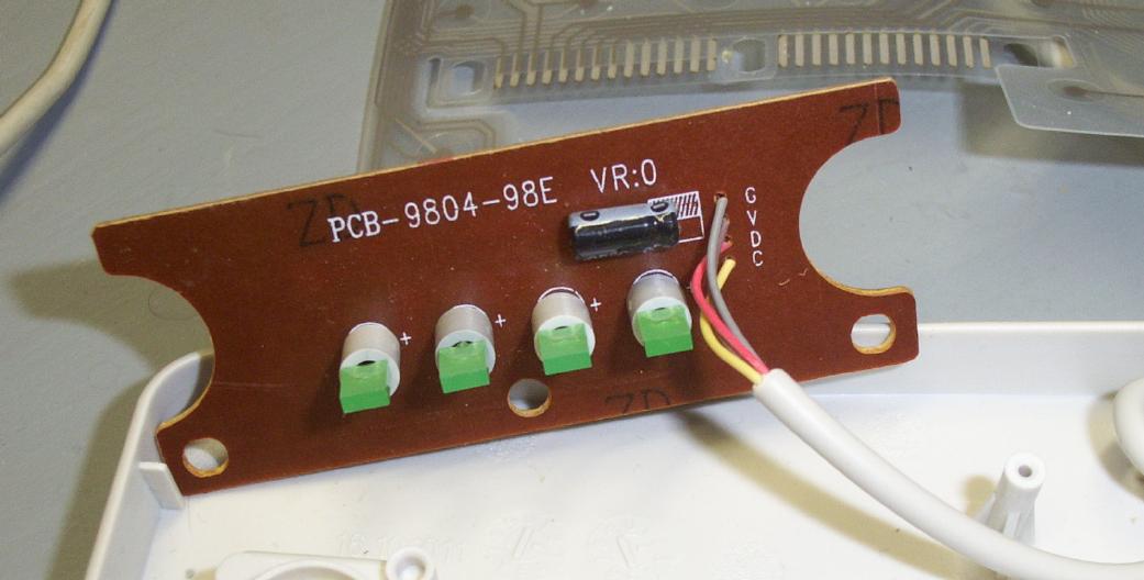
Component side. Oh wow! They where nice enough to label each of the keyboard's control lines. From the top: G is Ground, V is +5 VDC, D is DATA, C is CLOCK.
Here is a website which has all the keyboard connector pin-outs you'll need.
Here is a list of keyboard scan codes.
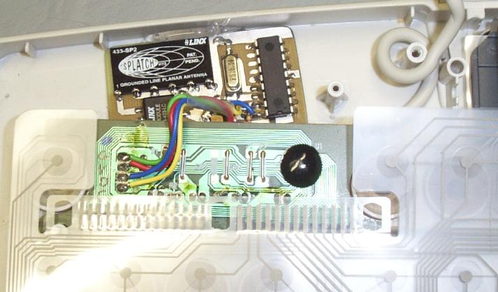
Installing the data tap inside the keyboard. Use a bit of hot-melt glue to hold it in place. Note how the antenna is away from anything which might block its transmissions. The antenna will be horizontally polarized.
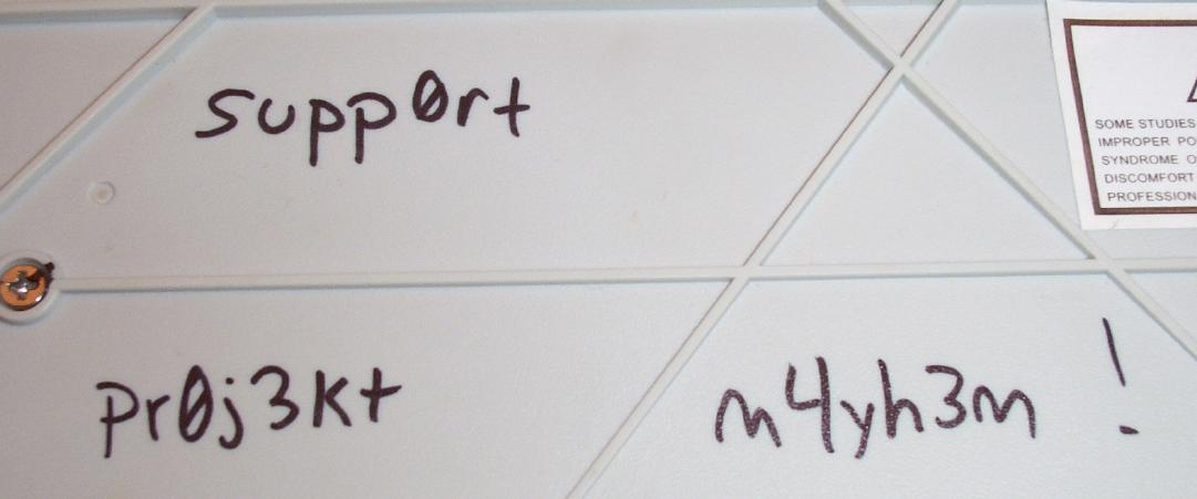
To protect your keyboard's safety, it would be a good idea to epoxy or super-glue all the screws holding it together. Then add a bit of "customization" which only a few will understand.
Receiver internal overview. It is powered from an internal 9 volt battery. Coaxial cable can be RG-174 or RG-196.
Front panel overview. Power switch is on the left. The center BNC jack is the antenna connection. LED is on the right.
DB-9 serial port connection. Radio Shack carries all the cables, connectors, and adapters you'll need for connection to your computer.
Receiver Software Operation
Connect the receiver to your computer, /dev/ttyS0, using a straight-through serial cable.
Make sure minicom is installed.
Fire up: minicom -s
Under the "Serial port setup" section, set:
   Serial Device             /dev/ttyS0
   Bps/Par/Bits              1200 8N1
   Hardware Flow Control     No
   Software Flow Control     No
Under the "Modem and dialing" section, null out the "Init string" setting.
Select "Save setup as dfl"
Fire up: minicom
Hit ALT-L to bring up the screen capture menu. Choose what file to save the output to.
Turn the receiver on and wait.
Hit ALT-X to exit or ALT-Z to go into configuration mode. The capture file is written on exit.
Here is an example capture file. It seems to be missing the "s" key.
Datasheets
Notes & Links